Week 12:Project 2-Meshing of Rear Wheel Holder challenge
MESHING OF AUTOMOTIVE REAR WHEEL HOLDER
AIM:
- To perform preprocessing on the given Rear Wheel Holder Sheet Metal component using hypermesh preprocessing software.
OBJECTIVE:
- To do geometric cleanup and generating midsurface of the automotive rear wheel holder.
- To generate mesh on the rear wheel holder with low tria concentration and proper mesh flow.
- To check the elements quality according to the given quality criteria.
- To assign a thickness for the component.
GIVEN DATA :
(1) MESH PARAMETER OF REAR WHEEL HOLDER
Target Element Length = 5 Units.
(2) QUALITY CRITERIA OF REAR WHEEL HOLDER
| S.NO | QUALITY CRITERIA | VALUE |
| 1. | Aspect ratio | 5 |
| 2. | Skewness | 45 |
| 3. | Warping | 15 |
| 4. | Taper | 0.5 |
| 5. | Min. length | 2 units |
| 6. | Max length | 8 units |
| 7. | Min angle quad | 45 |
| 8. | Max angle quad | 135 |
| 9. | Min angle tria | 20 |
| 10. | Max angle tria | 110 |
| 11. | Tria% | 10 |
GIVEN MODEL :
- IGES file of rear wheel holder.
SOFTWARE USED :
Preprocessing tool- Hyperworks desktop 2022.
INTRODUCTION : REAR WHEEL HOLDER.
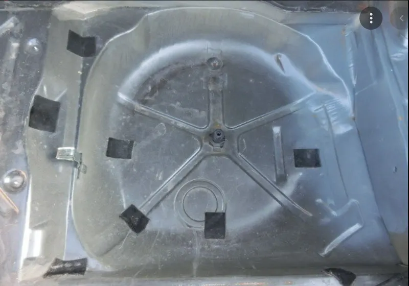
- It is a spare wheel floor panel which is used to keep the spare wheel in the car.
- A spare tire (or stepney) is an additional (tire or tyre) carried in a motor vehicle as a replacement for one that goes flat, has a blowout, or has another emergency.
- Spare tire is generally a misnomer as almost all vehicles actually carry an entire wheel with a tire mounted on it as a spare rather than just a tire, as fitting a tire to a wheel would require a motorist to carry additional, specialized equipment.
MERCEDES BENZ -WHEEL HOLDER
PROCEDURAL STEPS :
STEP 1 : IMPORTING THE MODEL
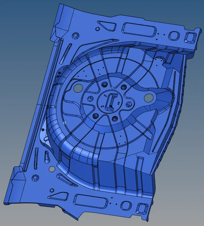
- Imported the given IGES file of the rear wheel holder for stepney spare wheel.
- File > import > geometry > selected the IGES file type > browsed to selected the iges file of the model > imported it.
Imported model of wheel holder
STEP 2 : ORGANISING THE COMPONENTS INTO SINGLE COMPONENT.
- Elements can be copied/moved into component collectors or groups.Lines, surfaces, solids, points, and connectors can be copied/moved into component collectors.
- selected the surfaces by the collectors and we are organizing it to one collector.
- Tool > Organize > Collector SubPanel > Switch to Surfaces > Selected by Collector >Moved it into the main component.
- Deleted the unwanted surfaces in the component tree.
Organising the components


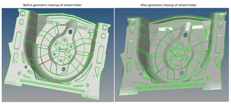
STEP 3 : GEOMETRIC CLEANUP ON PARENT GEOMETRY
- Geometric cleanup on the rear wheel holder by using manual method to below follwing steps.
- Set change from auto mode to by topo mode to check if there's any extra surface or free edges or missing surfaces are present or not.
- For this enable wireframe geometry mode and then try to observe and find irragularities anddiscontinuities in the model. If found then fix it manually.
- Fix this damaged surface by deleting the surface by Geometry > Quick edit > Delete Surface > Surface (Select).
- Fix the missing surfaces by Mainmenu > geometry > surfaces > ruled > selected the lines > filled the gaps between surfaces.
-
Geometry > Quickedit > split surface node-Select two locations of the nodes to split the surface and then select an additional node to continue to split the surface.
-
Geometry > Quickedit > Split surf-line-In this,select a node and select a line to split the surface,here the split will be perpendicular to the line chosen.
-
Geometry > Quick edit >Release points-Drag and select the surface,where you want release the points.After releasing the points.The free edges will exsists.
-
Geometry > Quick edit > Replace points-Move points from their current locations to the locations of other points,where we want them to replace it.
-
Geometry > Quick edit > Add/Remove points-Use window selection (with the left mouse button and right mouse button ) to add and remove any points within the selection box.
-
Geometry > Quick edit > Add points on line-Specify the number of points that we wish to add to that line, and then select the desired line in our model.
-
Geometry > Quick edit > Delete surface-Select the surface which we need to eliminate and delete it.
- Geometry > Quick Edit >Toggle Edges > Lines (Select)-Left-click a free edge (red) to make it shared (green), or a shared edge to make it suppressed (blue) and Right-click a suppressed edge to make it shared, or a shared edge to make it free.
- Geom > Quick Edit >filler surface > use the line selector to select a closed-loop line in the model to created a surface.
STEP 3 : THICKNESS MEASUREMENT.
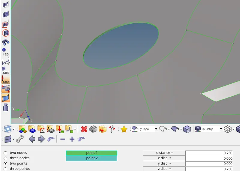
- Measured the thickness of the wheel holder - Geometry > distance > 2 points >selected the 2 points >distance measured is 0.75 mm.
- As per the thickness measurement , uniform thickness found out overall geometry on the inner panel.
Measured thickness of the model
STEP 4 : MIDSURFACE EXTRACTION.
- Uniform thickness found out overall geometry of the wheel holder so,extract midsurface by skin offset method.
- Newly created midsurface component is our current component. Midsurface extracted by Geometry > midsurface > extract option - offset+plane+sweep > selected the all surfaces >extracted it.
Midsurface of an wheel holder
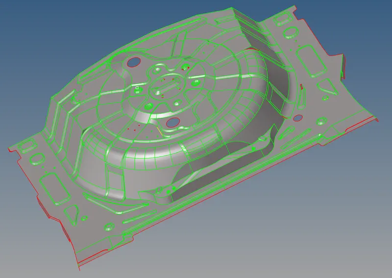
STEP 5: GEOMETRIC CLEANUP ON MIDSURFACE
- Do a geometric clean up on the mid surface extracted
- Check for the free edges in the middle region of mid surface.
- If there are any free edges,Toggle them and eliminate that free edges.
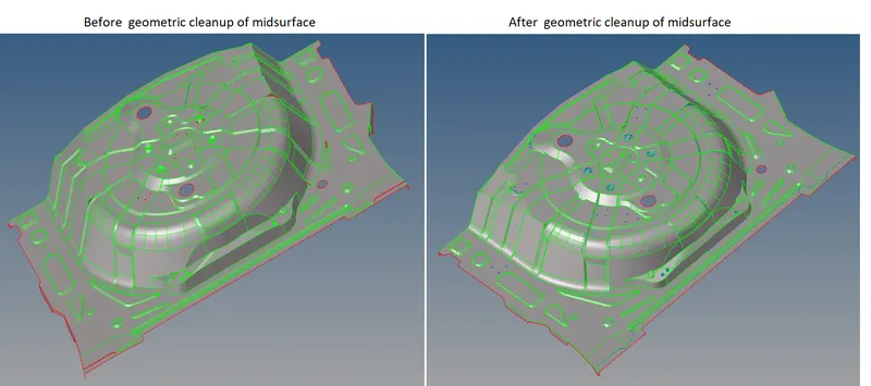
- Due to complexity of the features,The software was unable to extract a good mid surface.There are some surfaces overlapping and there is no connectivity ,So fix this manually.Do a manual geometric clean up.
- Geometric cleanup on the rear wheel holder by using manual method to below follwing steps.
- Checked for the duplicates,give a Clean UP Tolerance value as 0.1 and check. by Geom > defeature > Duplicates >> Surfaces (Displayed) >Cleanup Tol = 0.1 > Find > Delete.
- Filled the surfaces by using following tools called
- Filler Surface
- Ruled Surface
- Spline
- Skin.
- Some of the features inn midsurface not extended towards parent geometry in that case, trimming operation will followed by Mainmenu > geometry > surface edit > surfaces with plane > selected the 2 surfaces > checked both trim >trimmed it .
- Then go to dlelete option to deleted the trimmed unwanted surfaces by , tools > delete > seleted the surface > deleted it.
- Delete the small pin holes because it cant capture the pin hole surface,by tools > delete > seleted the surface > deleted it.
- After deleting that fill that holes with the filler surface by Geom > Quick Edit > filler surface > use the line selector to select a closed-loop (hole) line in the model to created a surface.
- Toggle the edges which are failing for minimum length by Geom > Quick Edit >Toggle Edges > Lines (Select) > toggled it.
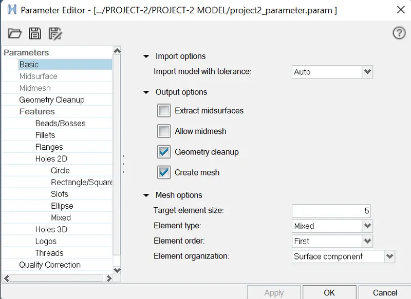
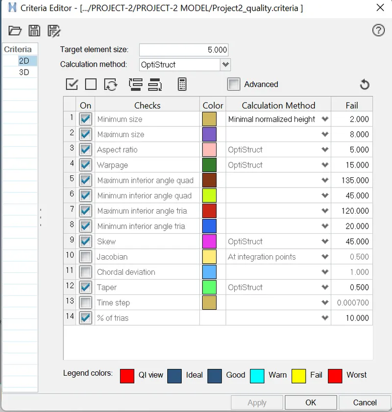
STEP 6 : SET THE MESH PARAMETER AND QUALITY CRITERIA VALUES.
- Before go to the meshing process, set the mesh parametes values and quality criteria values as per the given data.
- Title bar > Preferences > parameter file settings > basic > changed the parameter values as per the given data.
- Title bar > Preferences > quality criteria file settings > changed the quality criteria values as per the given data.
Set the mesh parameter and quality criteria values
STEP 7 : SURFACE MESHING ON REAR WHEEL HOLDER.
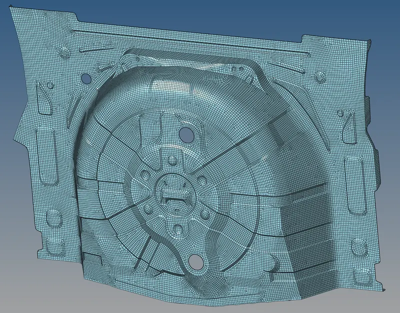
- Performed meshing on the rear wheel holder by automesh method.
- Mainmenu > 2D > automesh > set the target element size = 5mm > selected the surfaces > meshed it.
- Achieving proper mesh flow was followed by the below steps.
- Reduced the trias concentration by Mainmenu > 2D > edit element > split > selected the elements >draw a spliiting line by points > splitted the elements.
- Then Mainmenu > 2D > edit element > combine > selected 2 trias > combined into quads.
- Mainmenu > 2D > split > click refine elements > selected the elements by path > splitted into elements.
Then Mainmenu > 2D > edit element > combine > selected 2 trias > combined into quads. - Mainmenu > 2D > quality index > cleanup tools > Drag tria elements and combine tria elements > reduced the no of trias .
- Reduced the no of trias by Mainmenu > 2D > replace > node with other node > disabled the tria element.
After spliitting the elements to perform smmoth operation to get uniform mesh flow by,
Mainmenu > 2D > smooth > plates > selected the elements > set the iterationvalues as 1 or 10 > smoothed it. - Mainmenu > 2D > quality index > cleanup tools > smooth > selected the elements > smoothed it.
- After splitting the elements alignment node will be changed , so nodes will aligned by
Mainmenu > geometry > node edit > align node > selected the 1st and 2nd end node and selected nodes needs to be aligned. - To get the proper alignment of node with midsurface construction line by ,
Mainmenu > tools > project > click to line option > selected the nodes wants to align and selected theconstruction line and vector by nodes > alligned it. - To improve the mesh flow by using rebuild mesh option,
Mainmenu > 2D > rebuild mesh > selected the elements > proper mesh flow got it.
2D meshing of an rear wheel holder
STEP 8: CHECKING AND FIXING THE ELEMENTS FAILING FOR QUALITY CRITERIA
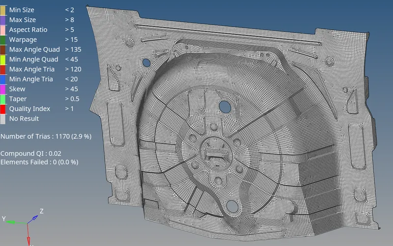
- Mainmenu > 2D > quality index > cleanup tools > set display threshold as fail > idenetified the elements which are failing for quality .
- Then , go to mainmenu > tools > check elements > 2D > set the quality criteria values a sper the geven data.
- Check the warpage quality by selected the elements which are failing for the warpage by save failed option.then go to mainmenu > tool >mask > selected the elements by retrieve > mask > reverse >showed the elements failing for warpage.
- Then go to the unmask adjacent option showed the adjacent elements, then its fixed by place node ,remesh, rebuild mesh options , element optimization and smooth in quality index.
- Then same as the above steps to be followed in other typed of fails then go to fixed the elements which are failing for aspect ratio, min length , max length , skewness , taper , min & max angle trias and min & max angle quads.
FE of an rear wheel holder with zero quality issues.
STEP 9 : MODEL CHECKUP
After meshing the entire component,Check for
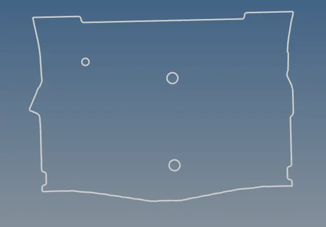
i) Connectivity [Free Edges].
ii) Duplicates.
iii) Normals.
STEP 9A : CHECK EDGES OF THE FE OF WHEEL HOLDER
- Firstly check the edges are in the model by ,
Mainmenu > tools > edges > selected the elements > set tolerance valueis 0.1 > run. - findout the unwanted edges in the elemets which are going to do preview equivalence and save equivalence it.
Fixed the free edges between the elements
STEP 9B : CHECK DUPLICATE ELEMENTS OF THE FE OF WHEEL HOLDER
- Checked for the duplicate elements
To check duplicates,Go to Main menu > Tool > Check Elements > Duplicates > if found the duplicat elementsdeleted it. - Then go to delete option to deleted the duplicate elements by , tools > delete > seleted the duplicated elements was found > deleted it.
STEP 9C : CHECK NORMALS OF THE FE OF WHEEL HOLDER
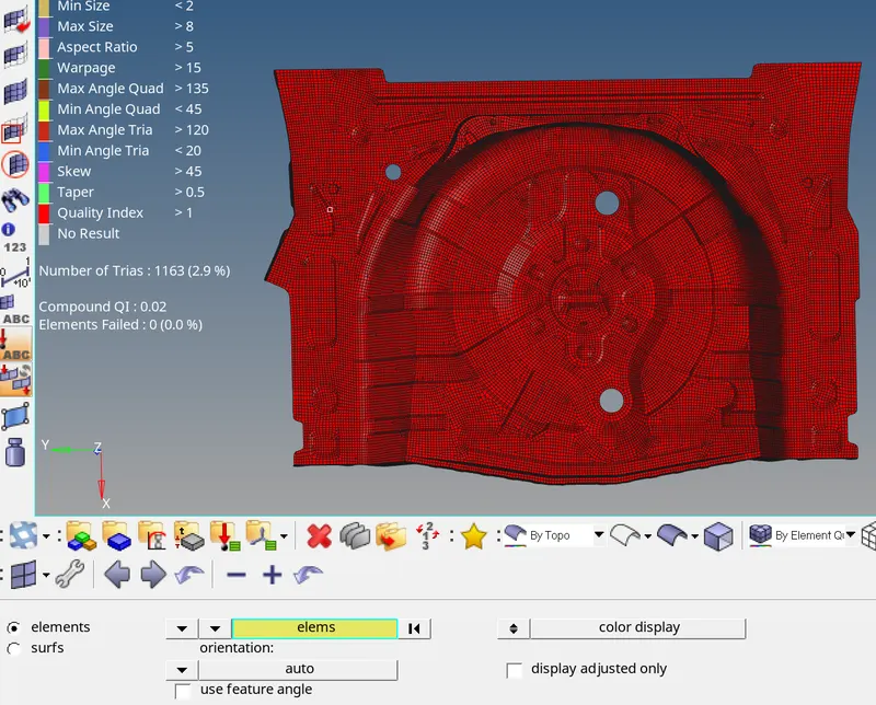
- Mainmenu > tools > normals > element >selected the elements by display > check color display > adjust the abnormal elements by adjust > normalised it
Checked normals of the FE model
STEP 10 : MATERIAL PROPERTIES AND THICKNESS ASSIGNING.
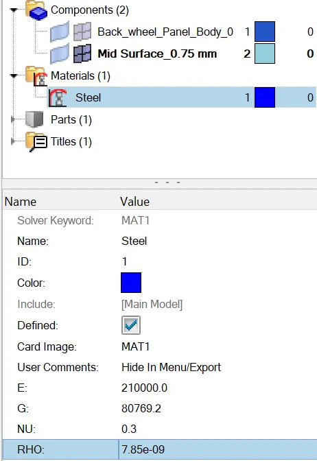
- Created material as STEEL for wheel holder.
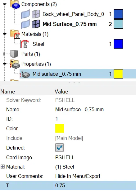
- Then Created new property for wheel holder, Set card image as a SHELL ,set the material as STEEL and assigning the thickness =0.75mm.
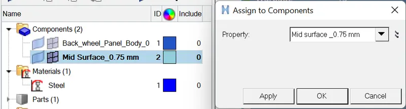
- Created material card and assigned material to the property card and then will assigned property card to wheel holder midsurface in the component tree. thickness assigned it.
Creation of material card Creation of property card
Thickness assigned to the FE of an model
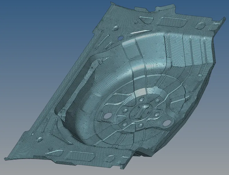
FINAL FE MODEL OF REAR WHEEL HOLDER WITH 2D ELEMENT REPRESENTATION
RESULT :
- Hence the mid surface has been extracted from the parent geometry.
- Hence there are no surface deformations in the geometry.
- A well connectivity has been established between the surfaces.
- The features have been captured properly
- A good mesh flow have been achieved with the zero elements failing for quality.
- Hence tria percentage with 2.9 % have been achieved.
LEARNING OUTCOME AND CONCLUSION :
In this project,I came to know
- How to mesh a complex sheetmetal component.
- How to extract the mid surface manually for the complex sheetmetal components.
- How to clean complex geometry and its midsurface.
- How to generate a proper mesh flow with low tria percentage.
- How to assign thickness to the components.