Assignment 3-2D Element Formulation Challenge
2D ELEMENT FORMULATION
AIM :
- To run the simulation for the given component with and without changing the recommended element parameters using a radioss solver.
OBJECTIVE :
- To change the run time to 55 ms and to change the number of animation steps minimum of 25 and maximum of 60.
- To run the base simulation with default element parameters.
- To check the energy error and mass error for the base simulation.
- To plot the graphs for kinetic energy, internal energy, hourglass energy, total energy, contact energy, and rigid wall forces.
- To run the new simulation with recommended element parameters and to plot the graphs again.
DATABASE :

SOFTWARE USED :
- Explicit Solver - Radioss.
PROCEDURAL STEPS :
CASE 1 : DEFAULT ELEMENT PROPERTIES OF THE STEEL RAIL
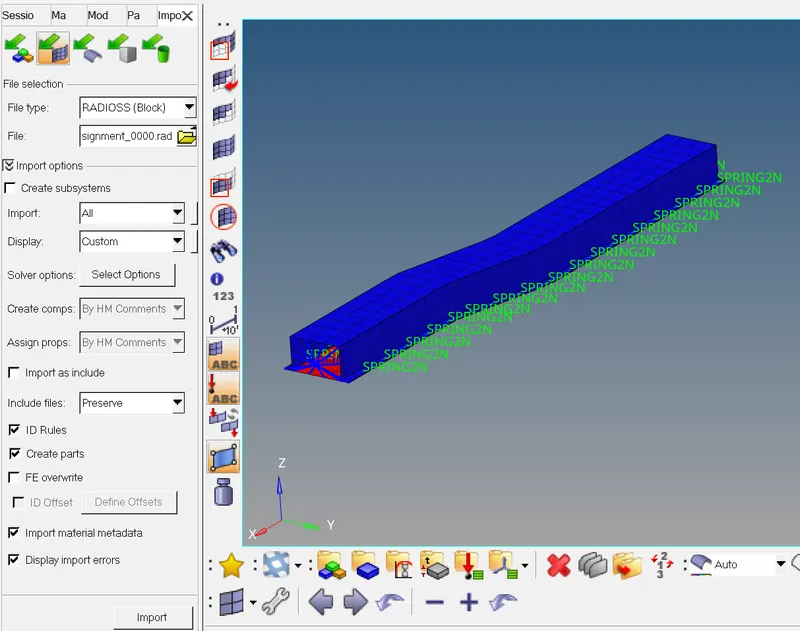
STEP1: Import the solver deck model.
- Inorder to import the .rad file by the following steps.
- File > import > solverdeck > file type- radioss block > file name as FIRST_RUN_0000.rad > imported it.
STEP 2 : To change the run time to 55 ms.
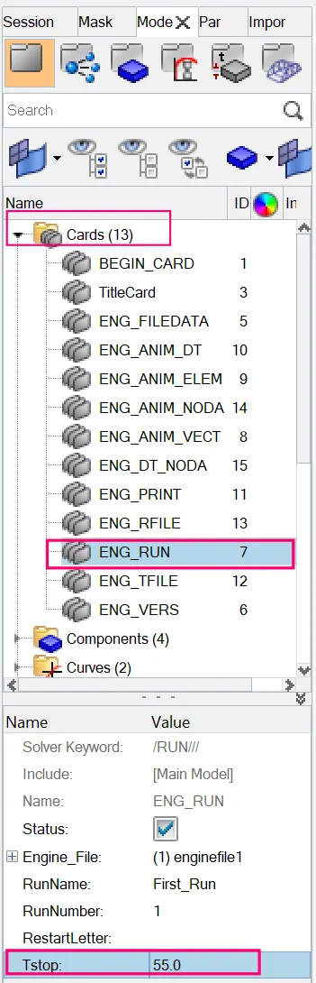
- To edit the run time parameter by the following steps.
- Model > Cards > ENG_RUN > set TStop is 55 ms.
STEP 3 : To change the number of animation steps minimum of 25 and maximum of 60.
- Engine file has to generate animation steps between 25 and 60, So we will take a number i.e. 35.
- This means that solver have to generate 35 animation file with in termination time of 55 ms.
Set the frequency of animation output to a time that will give 20 animation steps(/ANIM/DT)
T frequency = Termination time / animation time steps
= 55 / 35
T frequency = 1.571
Which means a solver has to generate animation file of each 1.571 ms time interval.
- In order to edit the card by the following steps.
- Model > Cards > ENG_ANIM_DT > updated the frquency value as 1.571 .
STEP 4 : To run the base simulation without any modification to element properties.
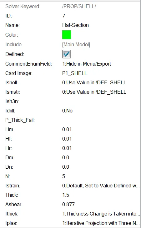
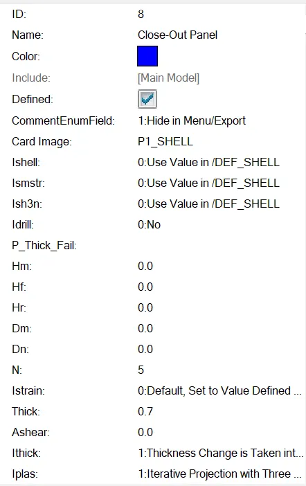
- Now we don’t have to edit the element properties. We have to keep it by default properties.
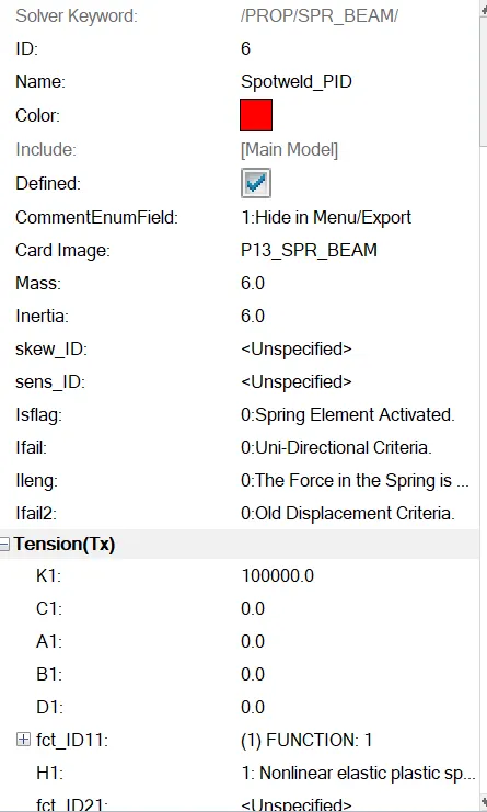
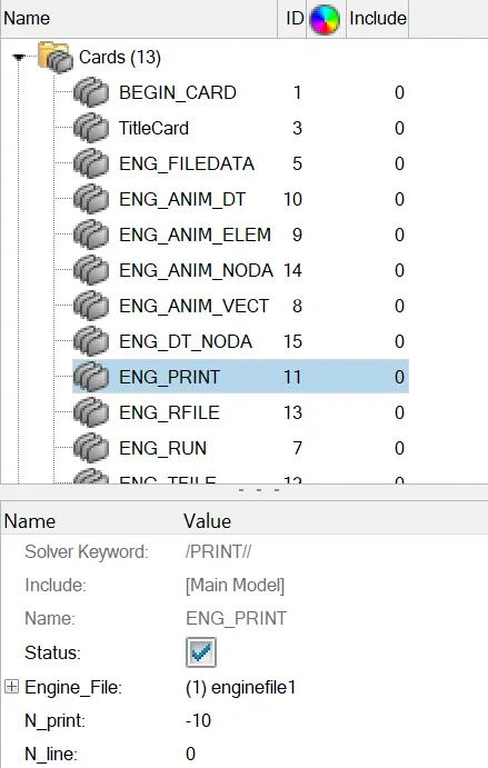
STEP 5 : Change /print -10.
- Here the print value -10 has been already setted default,So no need to change the print value.
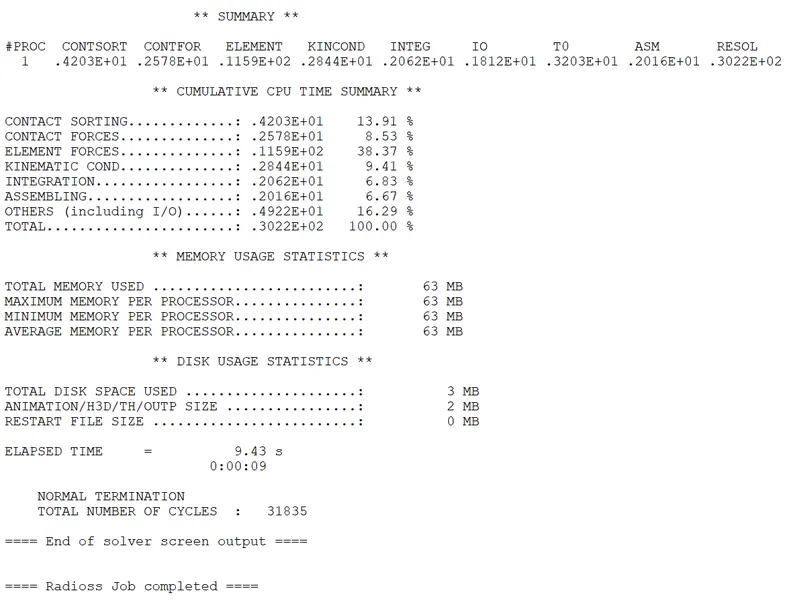
STEP6 : RADIOSS Job
- After entering the values in the control cards.
- Run solver.
- To do that,Go to Analysis panel in Panel Area > Radioss > Select the Input File > Radioss.

- Options helps to choose number of cores to solve this problem, here we have chosen 4 number of cores by (-nt 4).
- Then click on Radioss, and new window will get pop-up. A simulation will start to show result.
- After selecting the input file and completing the set up to run the solver.
- Radioss will pop the solver view stating Radioss Job Completed.
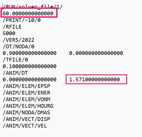
STEP 7 : Check engine [00001.rad] file
- After the end of the solver output,Go and check the whether the engine has been edited or not.
- To check,Go to file location where you have saved the starter file.
- Open the engine [00001.rad] file with notepad.
STEP 8 : Check animation files
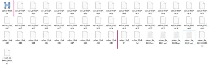
- We have eneterd the T frequency value to create 35 animation files,but 40 animation files have been created which is shown in below,
STEP 9 : Check errors.
- Now Engine Output File [00001.out] has been generated after analysis.
- The Engine Output File [00001.out] contains the data like
- Time Step.
- Energy Error.
- Mass Error.
- Internal Energy Error.
- Kinetic Energy Error.
- Contact Energy Error.
- Here check for the Mass Error and Energy Error.
- The obtained values for Energy Error,Mass Error,Internal Energy Error,Kinetic Energy Error and Contact Energy Error has been shown in below figure 35.
- The Acceptable Energy Error Range is -15% to +5%.
- The Acceptable Mass Error Range is 0 to 2%.
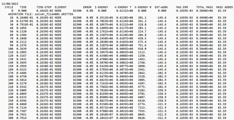
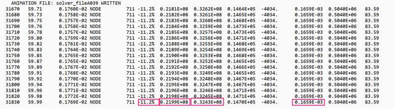
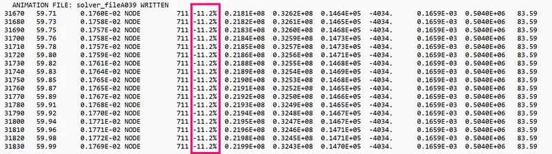
- The Maximum Energy Error is= -11.2%.
- The Maximum Internal Energy Error= 0.2199 E+08 gm (mm /ms²)
- The Maximum Kinetic Energy Error= 0.6128 E+08 gm (mm² /ms²)
- The Maximum Mass Error= 0.1659E-03 gm.
STEP 10 : Post processing
1) Review the Simulation using -HyperView.
2) Plot the graphs using -Hypergraph 2D.
1) Review the Simulation using -HyperView.
- First to begin the postprocessing in the Hypermesh,Split the Screen .
- Import the animation file .h3d into the hyperview.
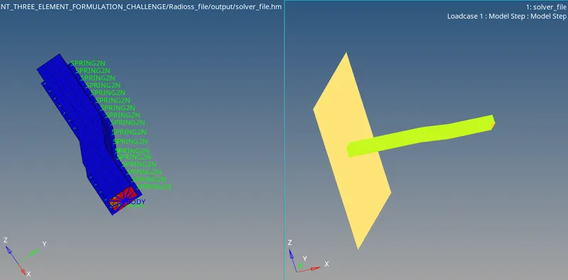
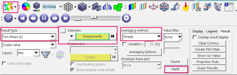
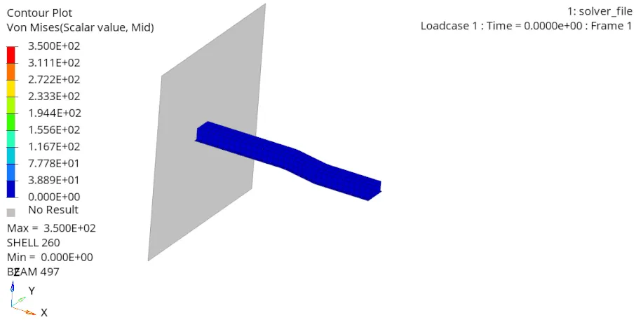
- After importing the .h3d file into the GUI,Enable the contour.
- The contour tool create contour plots of a model graphically visualize the analysis results.
- To enable contour,Go to Results > ToolBar > Contour .
- Now switch to the Von Misses Stress in result type and select the component,select the averaging method as simple and then click apply.
2) Plot the graphs using -Hypergraph 2D.
- Now plot the graphs using Hypergraph 2D,We are plotting the graphs to see what is happening in the rail component.
- Hypergraph 2D is a powerful data analysis and plotting tool with interfaces to many popular file formats.
- Here switch to the Hypergraph 2D to plot the graphs.
- To switch,Go to Client Selector > Choose the Hypergraph 2D.
2a) Plot of the Rigid Wall Forces.
- To plot the graph,go to Hypergraph 2D > Data File > Solver_file_T01 > Apply.

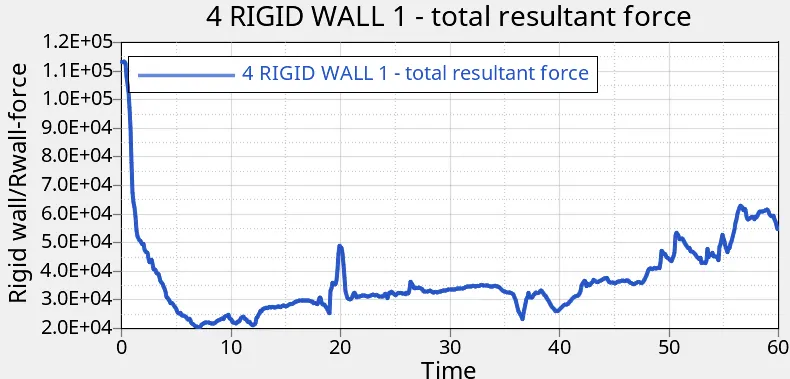
- When the rail component hits the rigid wall,The rigid wall forces increases maximum of 113439 N from the beginning.
- And it goes on decreasing minimum of 20376N Because the deformation is happening to the rail component when it hits to the rigid wall.
2a) Plot of the different energies .
- To plot the graph,go to Hypergraph 2D > Data File > Solver_file_T01 > Apply.

A. Kinetic Energy :
- Kinetic Energy is at peak in the starting,Why because,we have huge mass .
- To Check Mass,Go to Solver page > top bar >Tools > Mass Details > Mass,COG,Inertia.
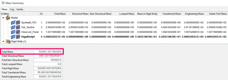
Total mass of the rail component = 503881 gm.
- To Check Velocity,Go to solver page > Top bar > View browser > hypermesh >solver > INIVEL Card > Initial Velocity.
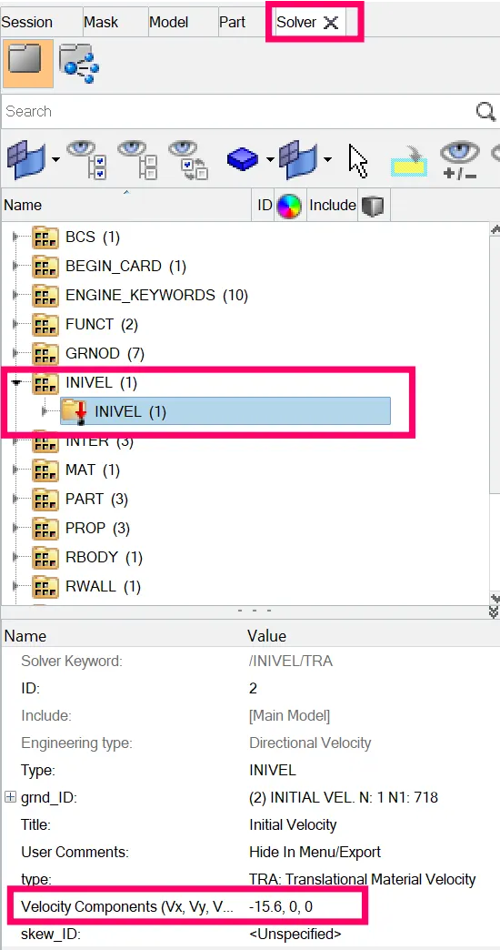
Velocity of the rail = 15.6 mm / ms.
Kinetic energy = 1/2mv^2
= 1/2 * 503881 * 15. 6
Kinetic energy = 61312240 `gm (mm² /ms²)`
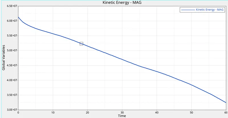
From this plot,
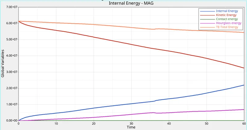
- Initially steel rail kinetic energy is 61314900 gm (mm² /ms²) high before hit the rigidwall , but steel rail kinetic energy after hitting the rigidwall gradually decreases at the end of the simulation is 32496366 gm (mm² /ms²). because initial velocity of the steel is high before hit the rigidwall then velocity gradually decreases because of deformation occured in the steel rail.
B. Internal energy :
- The formula for Internal Energy is I.E = Q±">±W.
- Here the heat is neglected,Cause there is no heat transfer,We will be having only workdone.
- W=FxD
- F=ma
- Initially internal energy of the steel rail is zero, because there is no deformation in the rigidwall. after steel rail hitting the rigidwall deformation occurs , then the internal energy of the rail gradually increases.
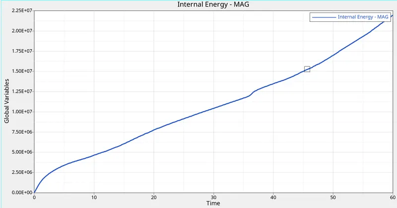
Max internal energy = 21928150 gm (mm /ms²)
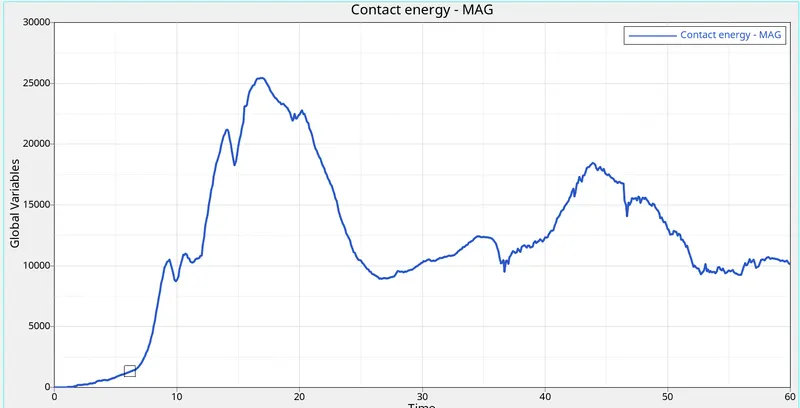
C. Contact energy :
- Initially there is no contact between steel rail and rigidwall, so there is no deformation and also contact energy is zero.
- After steel rail is hitting the rigidwall deformation happened, then the contact energy is increases as well as decreases.
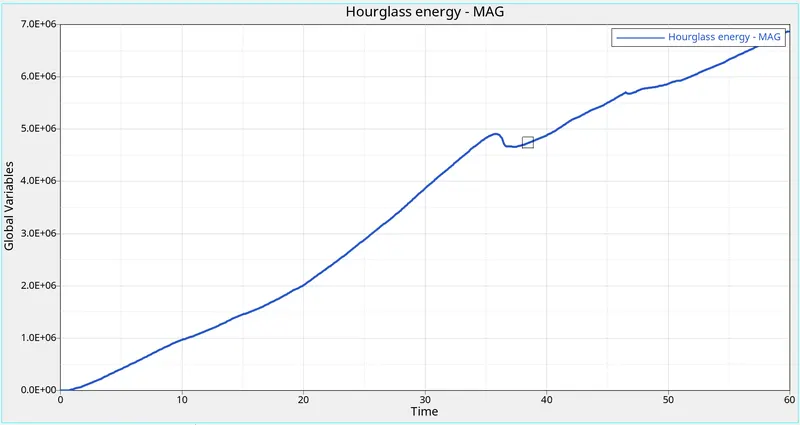
D. Hourglass Energy :
- The hourglass energy goes on increasing,Because to balance the rest of energies,An artificial energy is required,that is called hourglass energy and that's the reason why hourglass energy goes on increasing from origin.
-
Note: Δt > t ⇒ Hourglass Exsist.
Δt < t⇒ Hourglass won't Exsist.
Where Δ">Δt-Shockwave.
t - Time taken for the information.
E. Total energy
- Total Energy is sum of Kinetic Energy+Contact Energy+Hourglass Energy + Internal Energy.
- All energies are in initial condition except kinetic energy,So the kinetic energy is only there.
- Total Energy=Kinetic Energy+0+0+0.
- Kinetic energy is directly proportional to the total energy.
- So the total energy is increasing in the beginning.
- Due to 11.2 % of energy error,the total energy is decreasing.
Energy error
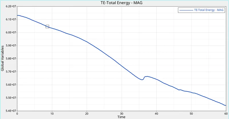
- Why Total energy is decreasing, Let's see mathematically
- Energy Error=11.2%
- = (11.2 / 100) x max.total energy
= (11.2 / 100) x 61314900
= 6867268 gm (mm² /ms²)
- Now Subract this value from Maximum Total Energy.
= 61314900 - 6867268
= 54447631 gm (mm² /ms²) same we got minimum total energy grom the above plot.
CASE 2 :RECOMMENDED ELEMENT PROPERTIES OF THE STEEL RAIL
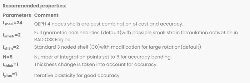
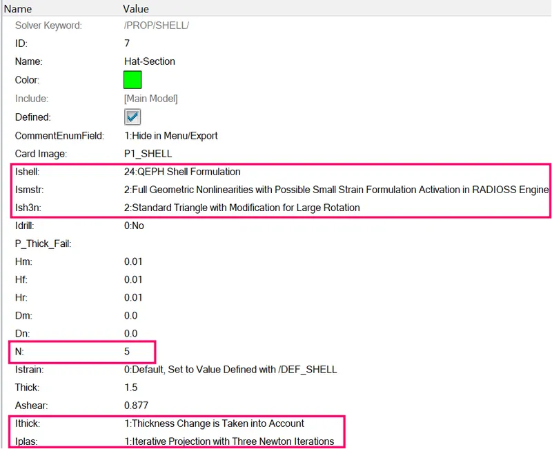
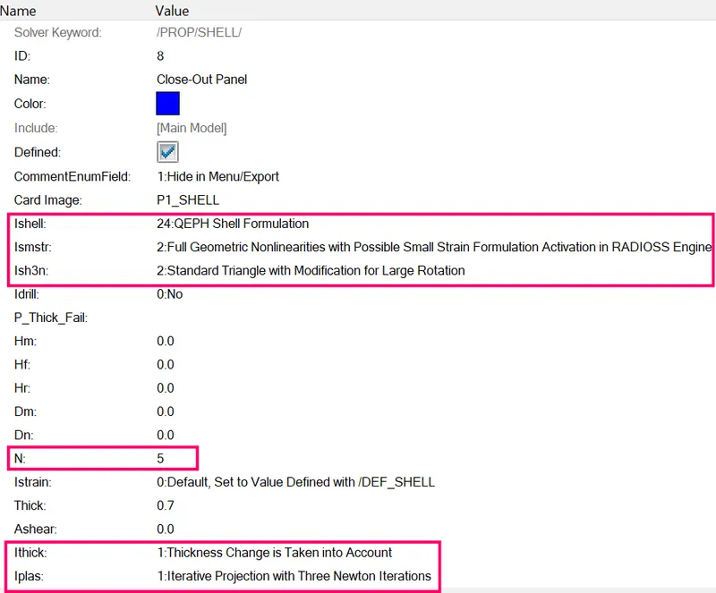
- Enter the reccommended parameters in properties called Hat-Section,Close-Out-Section which is given in the question.
- The recommended parameters have been enetered in the properties by the following steps.
- Do the same procedure of case one procedural steps from STEP 1 to STEP 8
STEP 9 : Check errors.
- Now Engine Output File [00001.out] has been generated after analysis.
- The Engine Output File [00001.out] contains the data like
- Time Step.
- Energy Error.
- Mass Error.
- Internal Energy Error.
- Kinetic Energy Error.
- Contact Energy Error.
- Here check for the Mass Error and Energy Error.
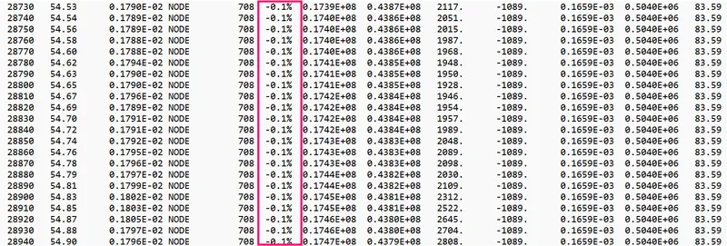
- The obtained values for Energy Error,Mass Error,Internal Energy Error,Kinetic Energy Error and Contact Energy Error has been shown in below figure 35.
- The Acceptable Energy Error Range is -15% to +5%.
- The Acceptable Mass Error Range is 0 to 2%.
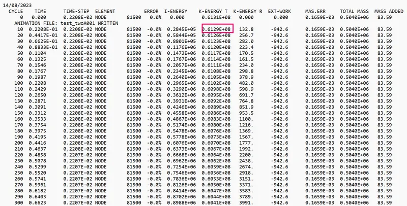
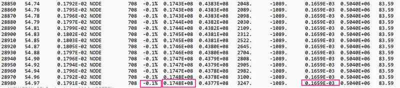
- The Maximum Energy Error is= -0.1 %.
- The Maximum Internal Energy Error= 0.1748 E+08 gm (mm /ms²)
- The Maximum Kinetic Energy Error= 0.6129 E+08 gm (mm² /ms²)
- The Maximum Mass Error= 0.1659E-03 gm.
STEP 10 : Post processing
1) Review the Simulation using -HyperView.
2) Plot the graphs using -Hypergraph 2D.
1) Review the Simulation using -HyperView.
- First to begin the postprocessing in the Hypermesh,Split the Screen .
- Import the animation file .h3d into the hyperview.
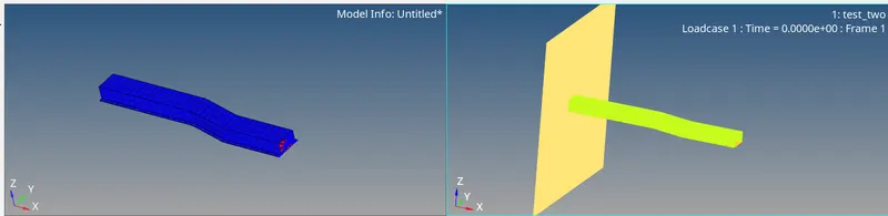
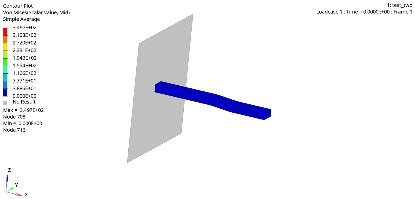
2) Plot the graphs using -Hypergraph 2D.
- Now plot the graphs using Hypergraph 2D,We are plotting the graphs to see what is happening in the rail component.
- Hypergraph 2D is a powerful data analysis and plotting tool with interfaces to many popular file formats.
- Here switch to the Hypergraph 2D to plot the graphs.
- To switch,Go to Client Selector > Choose the Hypergraph 2D.
2a) Plot of the Rigid Wall Forces.
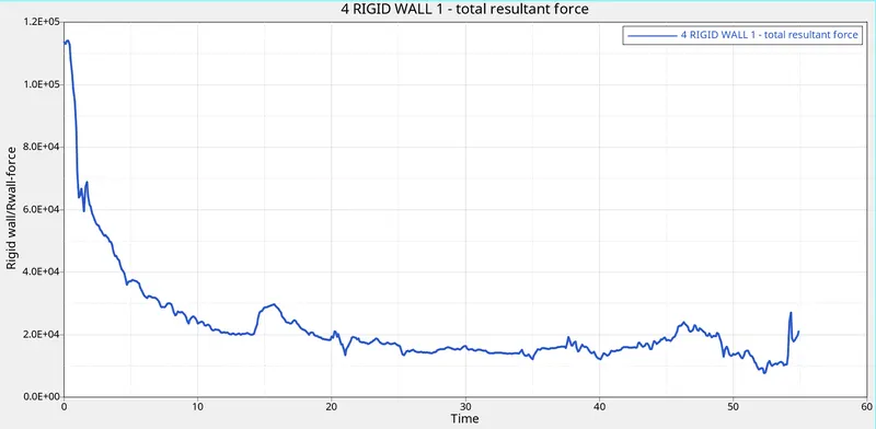
- When the rail component hits the rigid wall,The rigid wall forces increases maximum of 114153 N from the beginning.
- And it goes on decreasing minimum of 20663 N Because the deformation is happening to the rail component when it hits to the rigid wall.
2a) Plot of the different energies .
- To plot the graph,go to Hypergraph 2D > Data File > Solver_file_T01 > Apply.

A. Kinetic Energy :
- Kinetic Energy is at peak in the starting,Why because,we have huge mass .
- To Check Mass,Go to Solver page > top bar >Tools > Mass Details > Mass,COG,Inertia.
Total mass of the rail component = 503881 gm.
- To Check Velocity,Go to solver page > Top bar > View browser > hypermesh >solver > INIVEL Card > Initial Velocity.
Velocity of the rail = 15.6 mm / ms.
Kinetic energy = 1/2mv^2
= 1/2 * 503881 * 15. 6
Kinetic energy = 61312240 `gm (mm² /ms²)`
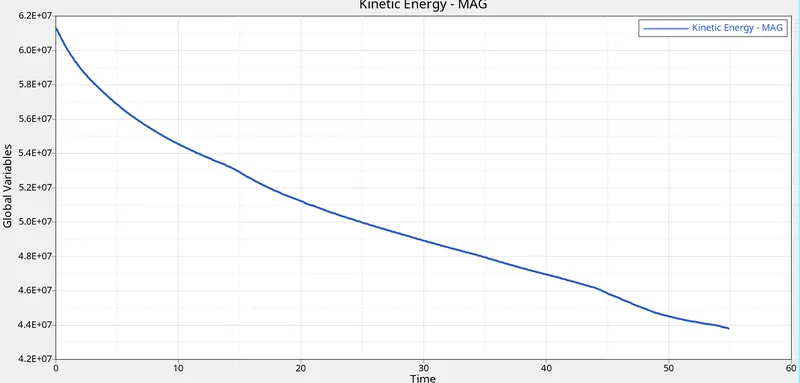
From this plot,
- Initially steel rail kinetic energy is 61314900 gm (mm² /ms²) high before hit the rigidwall , but steel rail kinetic energy after hitting the rigidwall gradually decreases at the end of the simulation is 43792244 gm (mm² /ms²). because initial velocity of the steel is high before hit the rigidwall then velocity gradually decreases because of deformation occured in the steel rail.
B. Internal energy :
- Initially internal energy of the steel rail is zero, because there is no deformation in the rigidwall. after steel rail hitting the rigidwall deformation occurs , then the internal energy of the rail gradually increases.
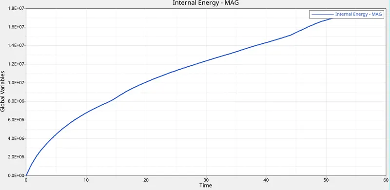
Max internal energy = 17465234 gm (mm /ms²).
C. Contact energy :
- Initially there is no contact between steel rail and rigidwall, so there is no deformation and also contact energy is zero.
- After steel rail is hitting the rigidwall deformation happened, then the contact energy is increases as well as decreases.
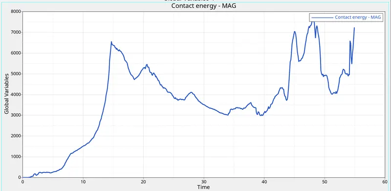
- Maximum contact energy = 7598.8
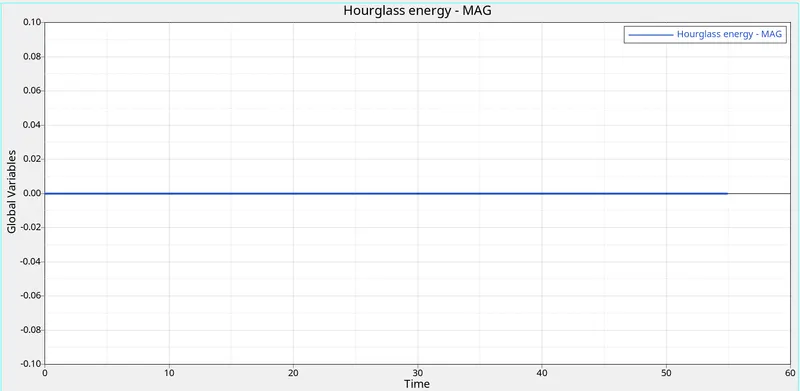
D. Hourglass Energy :
- The hourglass energy is zero, because
E. Total energy
- Total Energy is sum of Kinetic Energy+Contact Energy+Hourglass Energy + Internal Energy.
- All energies are in initial condition except kinetic energy,So the kinetic energy is only there.
- Total Energy=Kinetic Energy+0+0+0.
- Kinetic energy is directly proportional to the total energy.
- So the total energy is increasing in the beginning.
- Due to -0.1 % of energy error,the total energy is decreasing.
Energy error
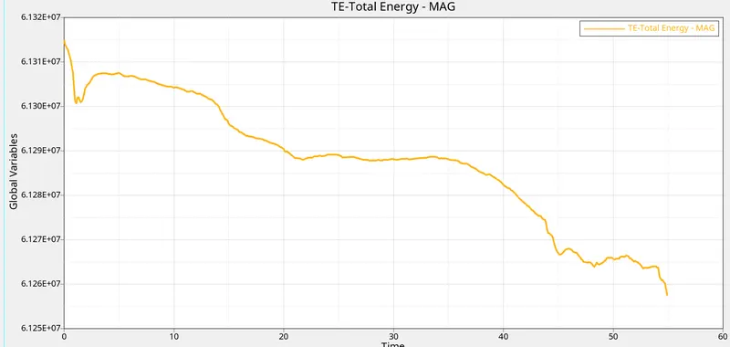
Minimum total energy = 61257480 gm (mm² /ms²)
- Why Total energy is decreasing, Let's see mathematically
- Energy Error= -0.1 %
- = (0.1 / 100) x max.total energy
= (0.1 / 100) x 61314900
= 61314.9 gm (mm² /ms²)
- Now Subract this value from Maximum Total Energy.
= 61314900 - 61314.9
= 61253585 gm (mm² /ms²) same we got minimum total energy grom the above plot.
Comparison of default element properties and recommended element properties of steel rail
| S.no | Description | Unit | Default element properties | Recommended element properties |
| 1. | Rigid wall -total internal force | N | 113439 | 114153 |
| 2. | Max kinetic energy | gm (mm² /ms²) | 61314900 | 61314900 |
| 3. | Min kinetic energy | gm (mm² /ms²) | 32496366 | 43792244 |
| 4. | Max internal energy | gm (mm /ms²) | 21928150 | 17465234 |
| 5. | Max contact energy | 25441 | 7598 | |
| 6. | Max hour glass energy | 6866264 | 0 | |
| 7. | Max total energy | gm (mm² /ms²) | 61314900 | 61314900 |
| 8. | Min total energy | gm (mm² /ms²) | 54424516 | 61257480 |
| 9. | Max Energy error | Percentage | - 11.2 % | - 0.1% |
| 10. | Mass error | 0.1659E-03 | 0.1659E-03 |
From the above table ,
- In default element properties of steel rail of total energy Increases and Slightly Decreases due to -11.2 % Energy Error.but recommended element properties of steel rail of Total Energy decreases slightly due to less - 0.1% energy error.
- In default element properties of steel railof hourglass Energy Increases due to balance all the energies, but recommended element properties of steel rail of Hourglass Energy Remains Constant that means hour glass is zero due to Recommended Shell Parameter.
Result :
- Hence the simulation has been runned without assigning recommended shell parameters.
- Hence the simulation has been runned with assigning recommended shell parameters.
- The graphs have been plotted for case-1 and case-2 successfully.
- While comparing Case-1 and Case-2,Case-2 is effective,because there is no hourglass deformation.
Conclusion and Learning Outcome :
- I conclude that Case-2 with assigning recommended shell parameters is effective.
- In this Challenge ,I came to know
- How to run a simulation with and without assigning shell parameters.
- How to do postprocessing (Plotting the graphs for the various parameters).
- How to understand the curves that are increasing and decreasing in the graphs.
- How to compare the obtained values with the various parameters.