week-11 Joint creation and Demonstration
JOINT CREATION AND DEMONSTRATION IN RIGID BODIES AND DEFORMABLE BODIES
AIM :
- To create the spherical, revolute, cylindrical, and translational joints between two rigid bodies and two deformable bodies by using Ls-dyna.
OBJECTIVE :
- To demonstrate the different types of joints like spherical, revolute, cylindrical & translational joints by using Ls-dyna manual.
DATA BASE :
- CONSTRAINED_EXTRA_NODES and *CONSTRAINED_NODAL_RIGID_BODY to create joints between rigid and deformable bodies respectively.
- Create the nodes at the required location, use *CONSTRAINED_EXTRA_NODES to include those nodes to the respective rigid bodies.
- The nodes should be part of a *CONSTRAINED_NODAL_RIGID_BODY which has some shared nodes with the deformable body.
DELIVERABLES :
- To demonstrate the joints' working, rotation and translatory motions.
- Input files for each of the joints and animations with their results.
SOFTWARE USED :
- Solver tool - LS-Prepost 4.7.17 and LS-Run 1.0.100838.
THEORETICAL FRAMEWORK :
(I) MECHANICAL JOINTS :
- A mechanical joint is a section of a machine which is used to connect one or more mechanical part to another.
- Mechanical joints may be temporary or permanent, most types are designed to be disassembled.
- Most mechanical joints are designed to allow relative movement of these mechanical parts of the machine in one degree of freedom, and restrict movement in one or more others.
(II) TYPES OF MECHANICAL JOINTS :
Diffrent types of mechanical joints are available but in this challenge we have discuss 4 joints as,
- Revolute joint.
- Spherical joint.
- Cylindrical joint.
- Translational joints.
1. Revolute joint.
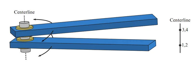
- A revolute joint (also called pin joint or hinge joint) is a one-degree of freedom kinematic pair used frequently in mechanisms and machines. The joint constraints the motion of two bodies to pure rotation along a common axis. The joint does not allow translation, or sliding linear motion.
- Revolute Joint. Nodes 1 and 2 are coincident; nodes 3 and 4 are coincident. Nodes 1 and 3 belong to rigid body A; nodes 2 and 4 belong to rigid body B. The relative motion of the two rigid bodies is restricted to rotations about the axis formed by the two pairs of coincident nodes. This axis is labeled the “centerline.”
2.Spherical joint.
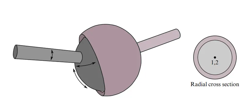
- The Ball Joint, also known as a spherical joint, has three rotational degrees of freedom between the two attached components. The two components are free to rotate relative to each other along all three axes.
- The relative motion of the rigid bodies is constrained so that nodes which are initially coincident remain coincident. In the below figure the socket’s node is not interior to the socket—LS-DYNA does not require that a rigid body’s nodes be interior to the body.
3.Cylindrical joint.
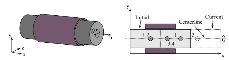
- A cylindrical joint is a two degree of freedom kinematic pair used in mechanisms. Cylindrical joints constrain two bodies to a single axis while allowing them to rotate about and slide along that axis.
- This joint is derived from the rotational joint by relaxing the constraints along the centerline. This joint admits relative rotation and translation along the centerline.
4.Translational joints.
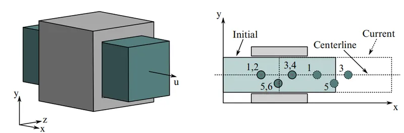
- A translational joint allows one part to translate along a vector in respect of another part. The parts can only translate, not rotate, in respect of each other. This joint has one translational degree of freedom, and the rotational degree of freedom is 0. An axis of the translation is the x-axis only.
- This is a cylindrical joint with a third pair of off-centerline nodes which restrict rotation. Aside from translation along the centerline, the two rigid bodies are stuck together.
PROCEDURAL STEPS :
CASE 1 : Creation of revolution joints between rigid bodies.
STEP 1A : Creation of square shell.
- First, two separate shell elements are created by using the following steps,
- Side bar > mesh > Element and Mesh > Shape Mesher > Select the entity as 4N shell > assign the node coordinates for a shell element with the required mesh density > create > accept and done.
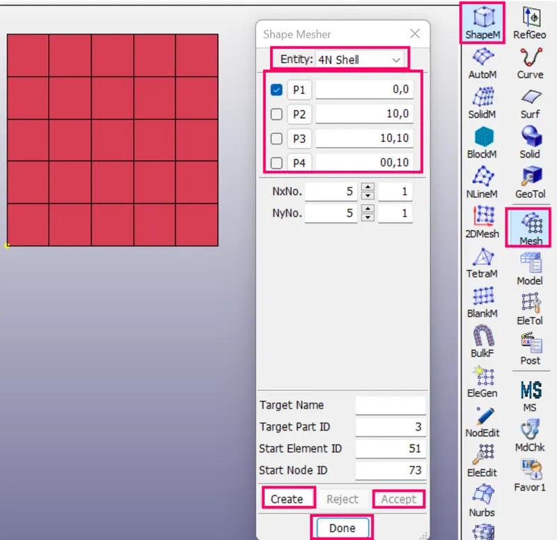
3. Then Create another shell part by the same above steps for created first shell part.
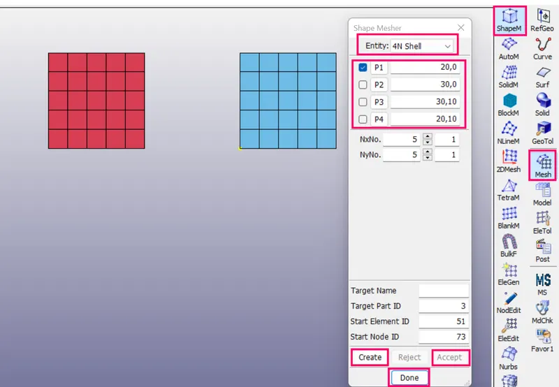
STEP 1B : Creation of material card for 2 shell bodies.
1. To create the material card for 2 shell bodies by the following steps.
2. I had prefereed to choose material type is MAT_RIGID_020
3. This is Material 20. Parts made from this material are considered to belong to a rigidbody.
4. Side bar > model and part > keyword manager > MAT > all > MAT_RIGID_020.
5. Created new ID is 1 and give title is Material_revolution_joint and specified the properties value as Kg-mm-ms unit system.
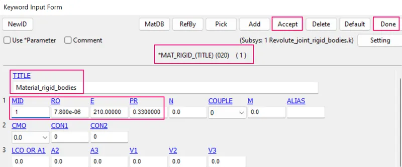
Where,
- RO- density of a steel = 7.8 * 10⁻⁶ Kg /mm³.
- E-Youngs modulus = 210 kg / mm ms²
- PR-Poissons ratio= 0.33.
STEP 1C : Creation of section card for 2 shell bodies.
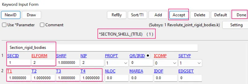
1. In this section element formulation ,integration rule ,nodal thickness and cross sectional properties are defined.
2. Side bar > model and part > keyword manager >all > section >specified the thickness value is 1.0 mm > accept and done.
STEP 1D : Assign the material card and section card to the rigid bodies part.
1. Inorder to create the rigid bodies shell part by the following steps.
2. Side bar > model and part > keyword manager >model > part > assigned the MID and SECID cards to rigid bodies part >accept and done.
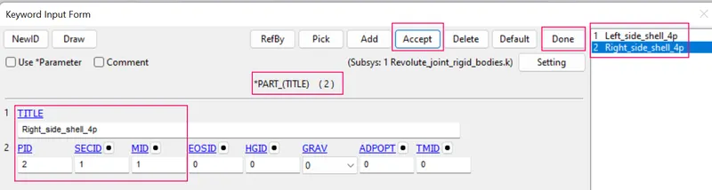
STEP 1E : Creation of revolute joint between two rigid bodies using *CONSTRAINED_EXTRA_NODES:
STEP 1E1 : Creation of extra nodes between two bodies.
- Create four extra nodes manually which are further needed to be associated with two parts for making a revolute joint.
- Create nodes by Element Tools > Node Editing > create > give distinct node IDs for 1st node > Node ID -501 > Node coordinates -(15,2) > create > acccept > done.
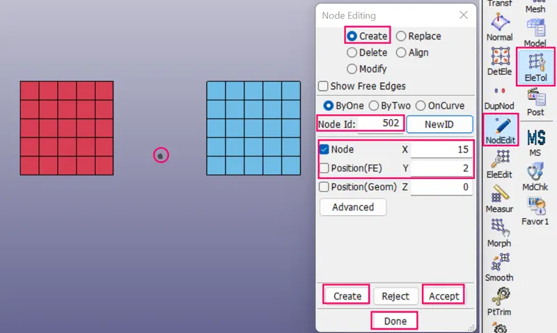
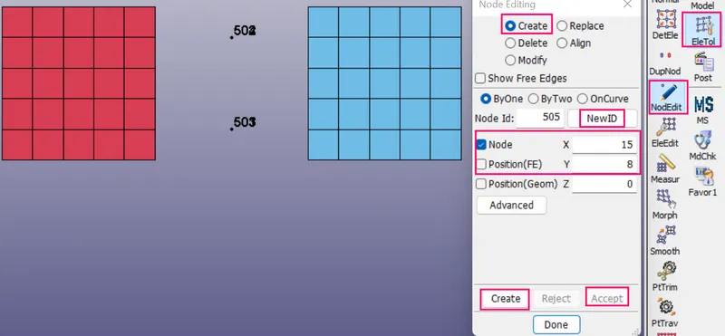
- Similary Created nodes by Element Tools > Node Editing > create > give distinct node IDs for 2nd node > Node ID -502 > Node coordinates -(15,8) > create > acccept > done.
- Created nodes by Element Tools > Node Editing > create > give distinct node IDs for 3rd node > Node ID -503 > Node coordinates -(15,2) > create > acccept > done.
- Created nodes by Element Tools > Node Editing > create > give distinct node IDs for 4th node > Node ID -504 > Node coordinates -(15,8) > create > acccept > done.
STEP 1E2 : Creation of node set for created extra nodes between two bodies.
Creation of First Nodeset
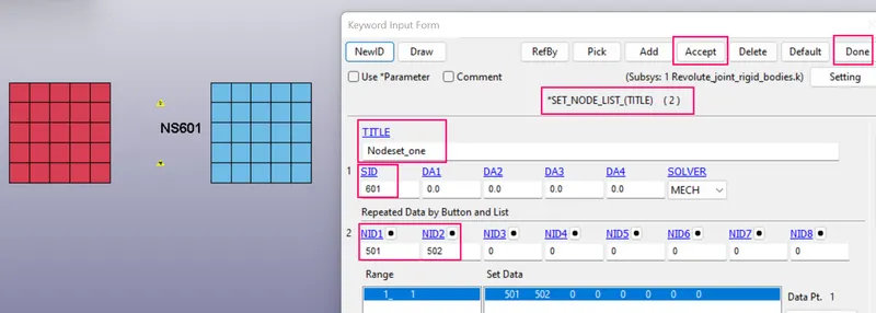
- Create new node sets, where nodes 501 and 502 belong to one node-set, and nodes 503 and 504 belong to another node-set. *SET_NODE_LIST keyword.
- Sidebar > create entity > SET DATA > SET NODE > selected the node ID 501 and 502 > give NSID-601 > title is Nodeset_one > apply > done.
- Checked the created node sets can through Sidebar > model > keyword manger > SET > NODE LIST > title as Nodeset_one > SID-601 > assigned the node IDs 501 and 502 > Created nodeset for that nodes > accept and done.
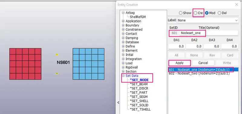
Creation of second Nodeset
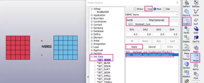
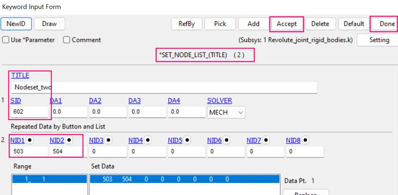
- similarly created the second nodeset for the nodes 503 and 504.
- Sidebar > create entity > SET DATA > SET NODE > selected the node ID 503 and 504 > give NSID-602 > title is Nodeset_two > apply > done.
- Checked the created node sets can through Sidebar > model > keyword manger > SET > NODE LIST > title as Nodeset_two > SID-602 > assigned the node IDs 503 and 504 > Created nodeset for that nodes > accept and done.
STEP 1E3 : To Associate the extra nodes to respective parts by *CONSTRAINED_EXTRA_NODES_SET
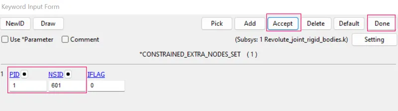
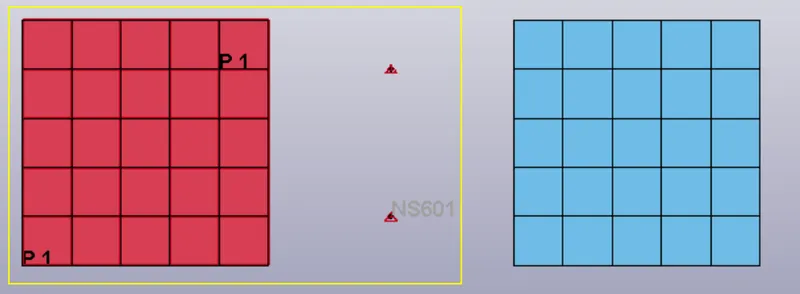
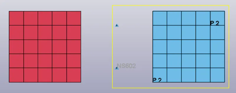
- These newly created nodes are in the space and do not belong to any of the parts now. So, for associating these nodes with part 1 and part 2, *CONSTRAINED_EXTRA_NODES_SET is used.
- That node 501 and 502 belong to part 1 and nodes 503 and 504 belong to part 2.
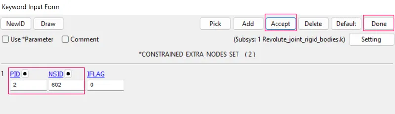
- Sidebar > keyword manager > model > all > constrained > CONSTRAINED_EXTRA_NODES_SET > set pid -1> assigned NSID -601 first shell part > accept and done.
- Sidebar > keyword manager > model > all > constrained > CONSTRAINED_EXTRA_NODES_SET > set pid > assigned NSID -602 second shell part > accept and done.
STEP 1E4 : Creation of *CONSTRAINED_JOINT_REVOLUTE card .
- Now, the revolute joint is defined by using *CONSTRAINED_JOINT keyword. Four nodes should be defined to create a revolute joint. N1 and N3 belong to body 1 and N2 and N4 belong to body 2. So, N1=501, N2=503, N3=502, and N4=504 are defined in the keyword.
- Sidebar > keyword manager > model > all > constrained > CONSTRAINED_JOINT_REVOLUTE > JID-1 > Title is Revolute_joint > assigned the node ids N1=501, N2=503, N3=502, and N4=504 > accept and done.

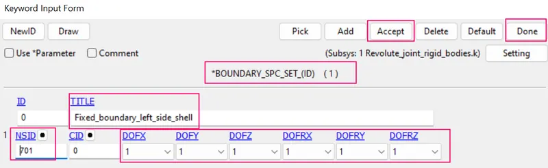
STEP 1E5 : Define a boundary condition (SPC) for shell part 1
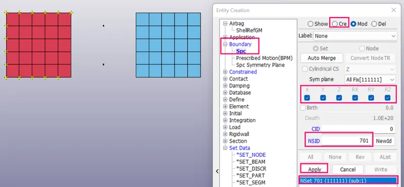
- Fixed shell part 1 of nodes is constrained in the X,y&Z direction because during revolution one shell part is fixed and other part is rotate about an axis.
- Inorder to create single point constrain by the following steps .
- Sidebar > model > create entity > boundary > spc > create > selected the node by path > nodes at the fixed end is constrained in both translational and rotational X,Y & Z direction > apply and done.
- Checked created SPC in shell part 1 in keyword manager.
- Sidebar > keyword manager > model >Boundary > SPC_SET > checked assigned the node set id > accept and done.
STEP 1E6 : Define a precribed motion boundary condition at one node of the shell part2
STEP 1E6(a) : Define a curve for precribed motion.
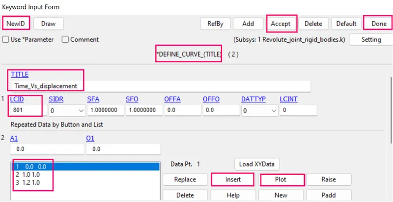
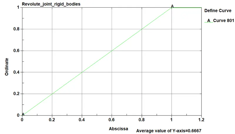
1. Before creation of prescribed motion at free node of the shell part2, we need to define a load curve for that prescribed motion.
2. In order to create a curve by the following steps.
3. Side bar > model and part > keyword manager >define > curve > LCID is 1001 > specify XY data > insert > accept and done.
STEP 1E6(b) : Creation of node set for the displacement at node of an shell part2
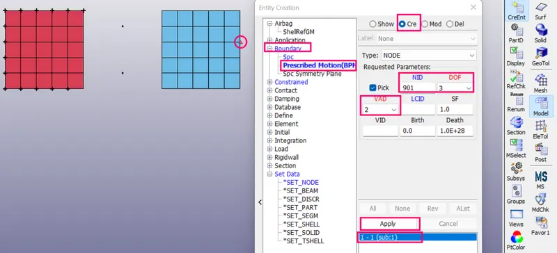
- In order to create the node set by the following steps.
- Sidebar > model > create entity > set data > set node > selected the node by pick at shell part2 > apply and done.
STEP 1E6(c) : Assign the Nodeset id and load curve to the boundary precribed motion set.
- In order to create the prescribed motion set at free end by the following steps.
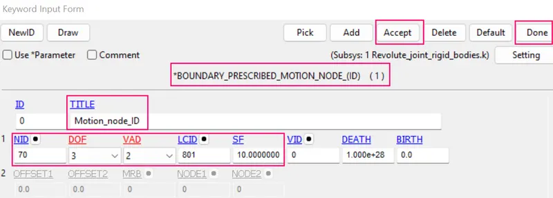
- Side bar > model and part > keyword manager > BOUNDARY_PRESCRIBED_MOTION_SET > assigned nodeset id 70 , DOF is (Z-translational DOF) , VAD is 2( Displacement rigid bodies and nodes) > assigned load curve for displacement LCID is 801 > accept and done.
STEP 1E7 : Define a control cards
STEP 1E7(a) : Define a curve for control time step.
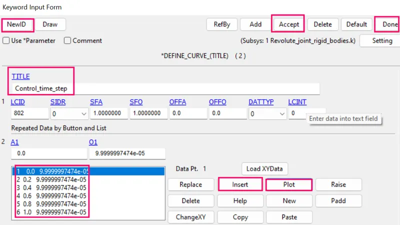
1. Before creation of control time step card , we need to define a load curve for control time step..
2. In order to create a curve by the following steps.
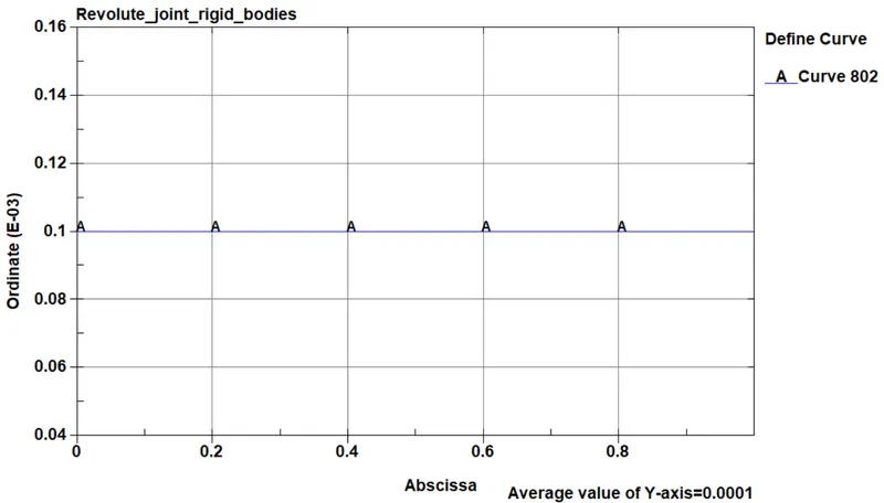
3. Side bar > model and part > keyword manager >define > curve > LCID is 802 > specify XY (control time step values) data > insert > accept and done.
STEP 1E7(b) : Define a control time step card.
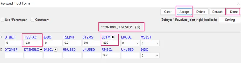
- *CONTROL_TIMESTEP card is used and a load curve is assigned through LCTM option.
- The time step calculated by the solver for these rigid bodies and this mesh size is large enough and hence for more stability we use smaller time steps for explicit analysis.
- In order to create control timestep card by the following steps.
- Sidebar > keywordmanager > all > control > timestep >TSSFAC-0.9 > assigned timestep load curve id-802 in LCTM option > accept and done.
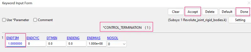
STEP 1E7(c) : Define a control termination card.
1. The main purpose of control termination card is to stop the job.
2. In order to assign the control termination card by the following steps.
3. Side bar > model and part > keyword manager > control > termination > specify termination time is 1 ms > accept and done.
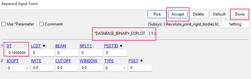
STEP 1E8 :Define the output database as Binary D3 plot.
- DATABASE_BINARY_D3PLOT ensures d3 plot files which its stores stress strain contour of the entire deformed model.
- In order to create the DATABASE_BINARY_D3PLOT by the fllowing steps.
- Side bar > model and part > keyword manager > database > select DATABASE_BINARY_D3PLOT > DT value is 0.1 ms is a time interval between output states > accept & done.
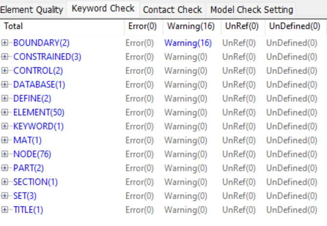
STEP 1F: Model checkup
- The model is checked for any errors before solving using model checker.
- After all the errors are cleared, the drop test setup is saved and is ready to run in LS DYNA manager for solving the scenario.
- Warnings we can ignore ,once model check is run , it will look like as shown in picture below
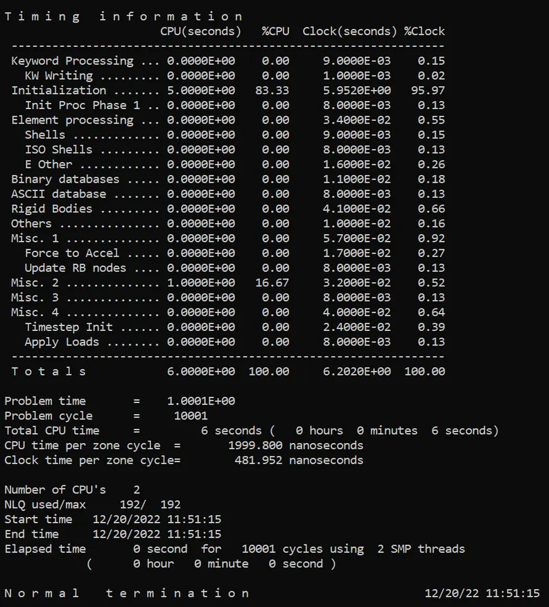
STEP 1G : Run the Simulation of Revolute joint between rigid bodies
- To run the using LS-run by the following steps.
- Title bar > file > run LS-dyna > runned the k file of revolute_joint_rigid_bodies > achieved normal temination. it means the model is ready for post processing.
- During simulation run window will popup as shown in picture below
STEP 1H : POST PROCESSING
- In order to see simulation results , we have to open output file in LS-Prepost by the following steps.
- In LS-prepost -Title bar > file > open > LS -Dyna binary plot > selected the d3 plot file > visibled to see animation file.
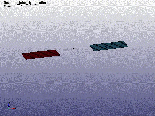
CASE 2 : Creation of revolution joints between deformable bodies.
- In this case same FE shell model used as previous case1.
- Delete other keywords and saved as a revolute_joint_deformable_bodies.K file.
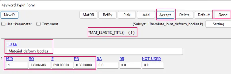
STEP 2A : Creation of material card for 2 shell bodies.
1. To create the material card for 2 shell bodies by the following steps.
2. I had prefereed to choose material type is MAT_ELASTC_001
3. This is Material Type 1. This is an isotropic hypoelastic material and is available for beam, shell, and solid elements in LS-DYNA
4. Side bar > model and part > keyword manager > MAT > all > MAT_ELASTC_001
5. Created new ID is 1 and give title is Material_revolution_joint and specified the properties value as Kg-mm-ms unit system.
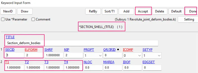
STEP 2B : Creation of section card for 2 shell bodies.
1. In this section element formulation ,integration rule ,nodal thickness and cross sectional properties are defined.
2. Side bar > model and part > keyword manager >all > section >specified the thickness value is 1.0 mm > accept and done.
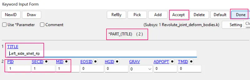
STEP 2C : Assign the material card and section card to the deformable bodies part.
1. Inorder to create the rigid bodies shell part by the following steps.
2. Side bar > model and part > keyword manager >model > part > assigned the MID and SECID cards to deformable bodies part >accept and done.
STEP 2E : Creation of revolute joint between two deformable bodies using *CONSTRAINED_NODAL_RIGID_BODY(CNRB).
STEP 2E1 : Creation of extra nodes between two bodies.
- At first, four separate nodes are created which would be further used to create CNRBs.
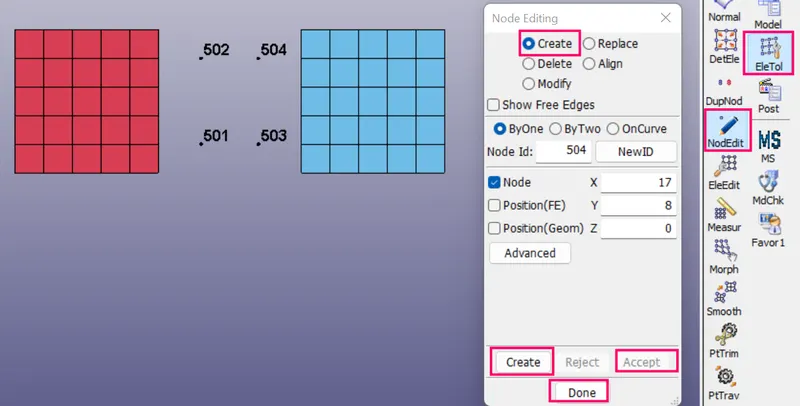
- Create nodes by Element Tools>Node Editing option and give distinct node IDs for all four nodes. Here four nodes are numbered as 501,502,503 and 504.
- Create four extra nodes manually which are further needed to be associated with two parts for making a revolute joint.
- Create nodes by Element Tools > Node Editing > create > give distinct node IDs for 1st node > Node ID -501 > Node coordinates -(13,2) > create > acccept > done.
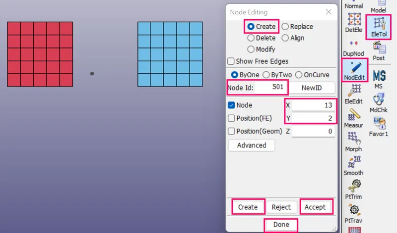
- Similary Created nodes by Element Tools > Node Editing > create > give distinct node IDs for 2nd node > Node ID -502 > Node coordinates -(13,8) > create > acccept > done.
- Created nodes by Element Tools > Node Editing > create > give distinct node IDs for 3rd node > Node ID -503 > Node coordinates -(17,2) > create > acccept > done.
- Created nodes by Element Tools > Node Editing > create > give distinct node IDs for 4th node > Node ID -504 > Node coordinates -(17,8) > create > acccept > done.
STEP 2E2 : To Associate extra nodes to respective parts by *CONSTRAINED NODAL RIGID BODY (CNRB)
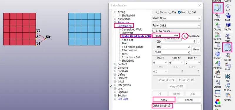
- Create Entity > Constrained > Nodal Rigid Body(CNRB) > Create.
- Toggle off the CrePNode option which will disable the creation of PNODE at the mass center of selected nodes.
- Now specify the PND is 501 node as the first point followed by node 31, node32 and node 33 and hit apply option.
- A CNRB will be created with PNODE at the 501 node position.
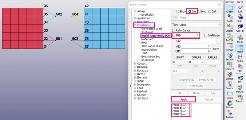
5.Similarly, create a other 3 CNRBs with PNODEs as 502, 503 and 504.
STEP 2E3 : Creation of Node pairs for revolute joint.
- Now, according to the condition for revolute joint node 501 and 503 should coincide and similarly node 502 and node 504 should coincide.
- In order to create the node pair by the following steps.
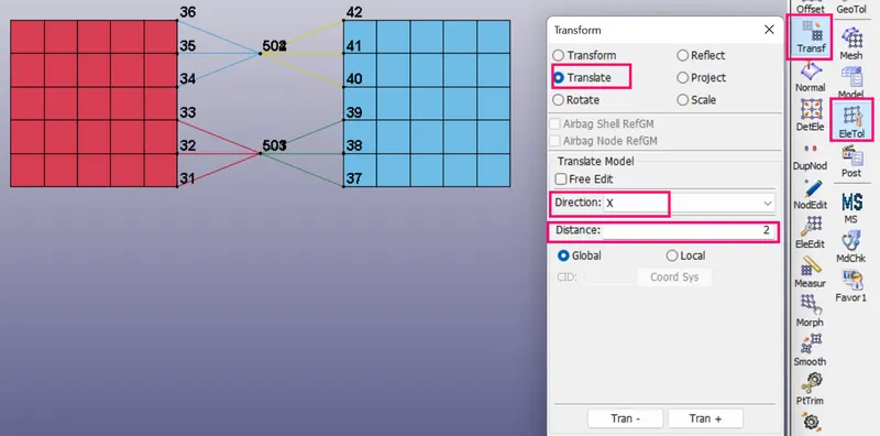
- For node 501 as,Element Tools > Transform > Translate > specify the direction as X > distance to coincidence to two nodes (501 and 503 ) is 2 > pick the node 501 > click translate(+) > accept and done.
- For node 503 as, Element Tools > Transform > Translate > specify the direction as X > distance to coincidence to two nodes (501 and 503 ) is 2 > pick the node 503 > click translate(-) > accept and done.
- For node 502 as,,Element Tools > Transform > Translate > specify the direction as X > distance to coincidence of two nodes (502 and 504 ) is 2 > pick the node 502 > click translate(+) > accept and done.
- For node 504 ,Element Tools > Transform > Translate > specify the direction as X > distance to coincidence of two nodes (502 and 504 ) is 2 > pick the node 504 > click translate(-) > accept and done.
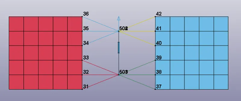
- Node pairs (501&503), (502&504) are created.
STEP 2E4 : Creation of *CONSTRAINED_JOINT_REVOLUTE card .
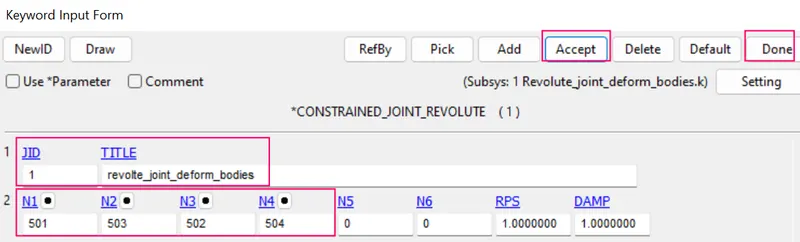
- Now, the revolute joint is defined by using *CONSTRAINED_JOINT keyword. Four nodes should be defined to create a revolute joint. N1 and N3 belong to body 1 and N2 and N4 belong to body 2. So, N1=501, N2=503, N3=502, and N4=504 are defined in the keyword.
- Sidebar > keyword manager > model > all > constrained > CONSTRAINED_JOINT_REVOLUTE > JID-1 > Title is Revolute_joint > assigned the node ids N1=501, N2=503, N3=502, and N4=504 > accept and done.
STEP 2E5 : Define a boundary condition (SPC) for shell part 1
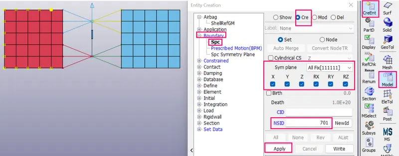
- Fixed shell part 1 of nodes is constrained in the X,y&Z direction because during revolution one shell part is fixed and other part is rotate about an axis.
- Inorder to create single point constrain by the following steps .
- Sidebar > model > create entity > boundary > spc > create > selected the node by path > nodes at the fixed end is constrained in both translational and rotational X,Y & Z direction > apply and done.
- Checked created SPC in shell part 1 in keyword manager.
- Sidebar > keyword manager > model >Boundary > SPC_SET > checked assigned the node set id > accept and done.
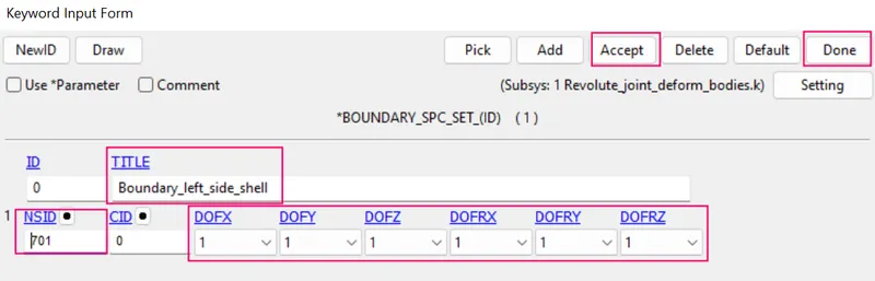
STEP 2E6 : Define a precribed motion boundary condition at one node of the shell part 2
STEP 2E6(a) : Define a curve for precribed motion.
1. Before creation of prescribed motion at free node of the shell part2, we need to define a load curve for that prescribed motion.
2. In order to create a curve by the following steps.
3. Side bar > model and part > keyword manager >define > curve > LCID is 1001 > specify XY data > insert > accept and done.
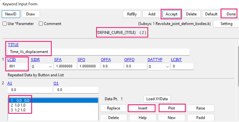
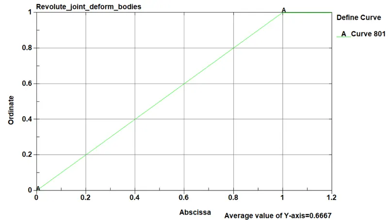
STEP 2E6(b) : Assign the Nodeset id and load curve to the boundary precribed motion set.
- In order to create the prescribed motion ndoe at shell part2 by the following steps.
- Side bar > model and part > keyword manager > BOUNDARY_PRESCRIBED_MOTION_SET > picked the node id-70 , DOF is 3 (Z-translational DOF) , VAD is 2( Displacement rigid bodies and nodes) > assigned load curve for displacement LCID is 801 > accept and done.
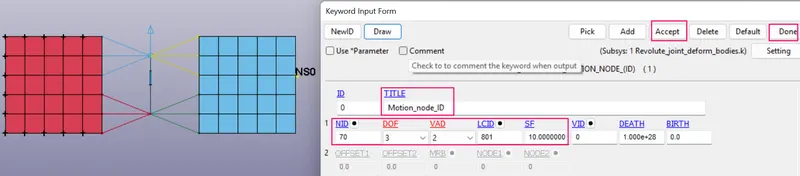
STEP 2E7 : Define a control cards
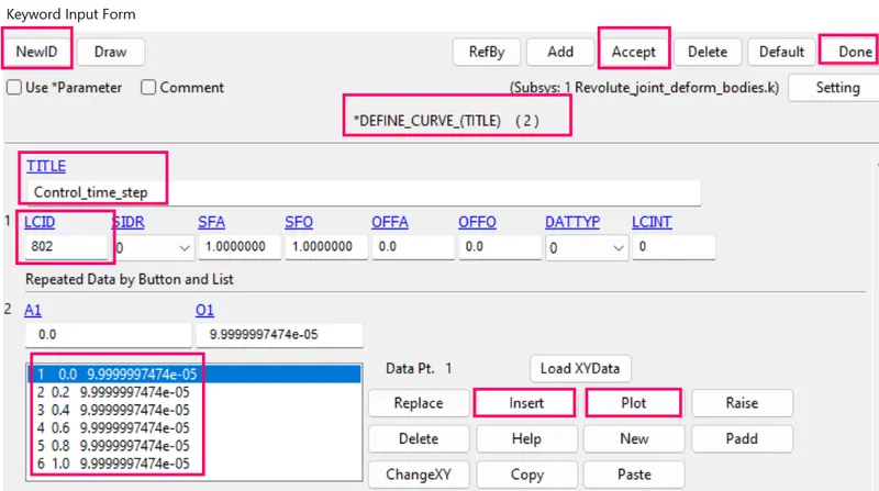
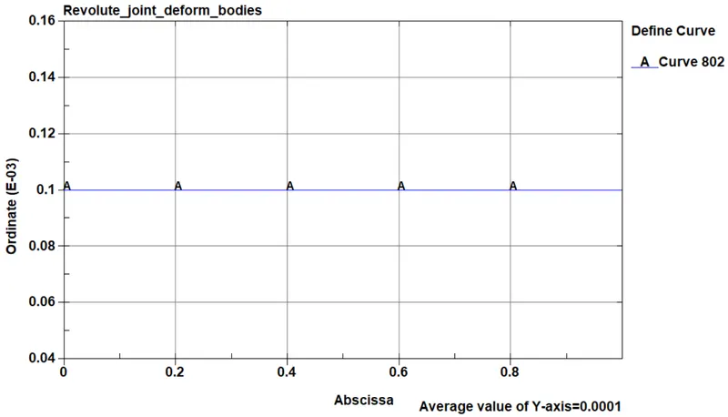
STEP 2E7(a) : Define a curve for control time step.
1. Before creation of control time step card , we need to define a load curve for control time step..
2. In order to create a curve by the following steps.
3. Side bar > model and part > keyword manager >define > curve > LCID is 802 > specify XY (control time step values) data > insert > accept and done.
STEP 2E7(b) : Define a control time step card.
- *CONTROL_TIMESTEP card is used and a load curve is assigned through LCTM option.
- The time step calculated by the solver for these rigid bodies and this mesh size is large enough and hence for more stability we use smaller time steps for explicit analysis.
- In order to create control timestep card by the following steps.
- Sidebar > keywordmanager > all > control > timestep >TSSFAC-0.9 > assigned timestep load curve id-802 in LCTM option > accept and done.
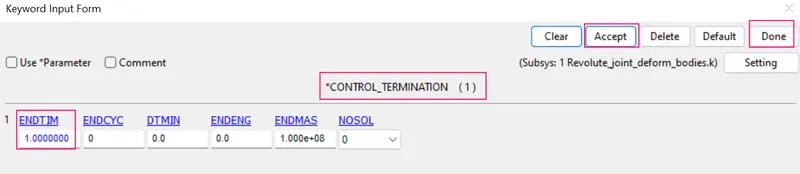
STEP 2E7(c) : Define a control termination card.
1. The main purpose of control termination card is to stop the job.
2. In order to assign the control termination card by the following steps.
3. Side bar > model and part > keyword manager > control > termination > specify termination time is 1 ms > accept and done.
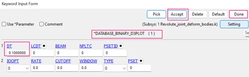
STEP 2E8 :Define the output database as Binary D3 plot.
- DATABASE_BINARY_D3PLOT ensures d3 plot files which its stores stress strain contour of the entire deformed model.
- In order to create the DATABASE_BINARY_D3PLOT by the fllowing steps.
- Side bar > model and part > keyword manager > database > select DATABASE_BINARY_D3PLOT > DT value is 0.1 ms is a time interval between output states > accept & done.
STEP 2F: Model checkup
- The model is checked for any errors before solving using model checker.
- After all the errors are cleared, the drop test setup is saved and is ready to run in LS DYNA manager for solving the scenario.
- Warnings we can ignore ,once model check is run , it will look like as shown in picture below
STEP 2G : Run the Simulation of revolute joint between deformable bodies
- To run the using LS-run by the following steps.
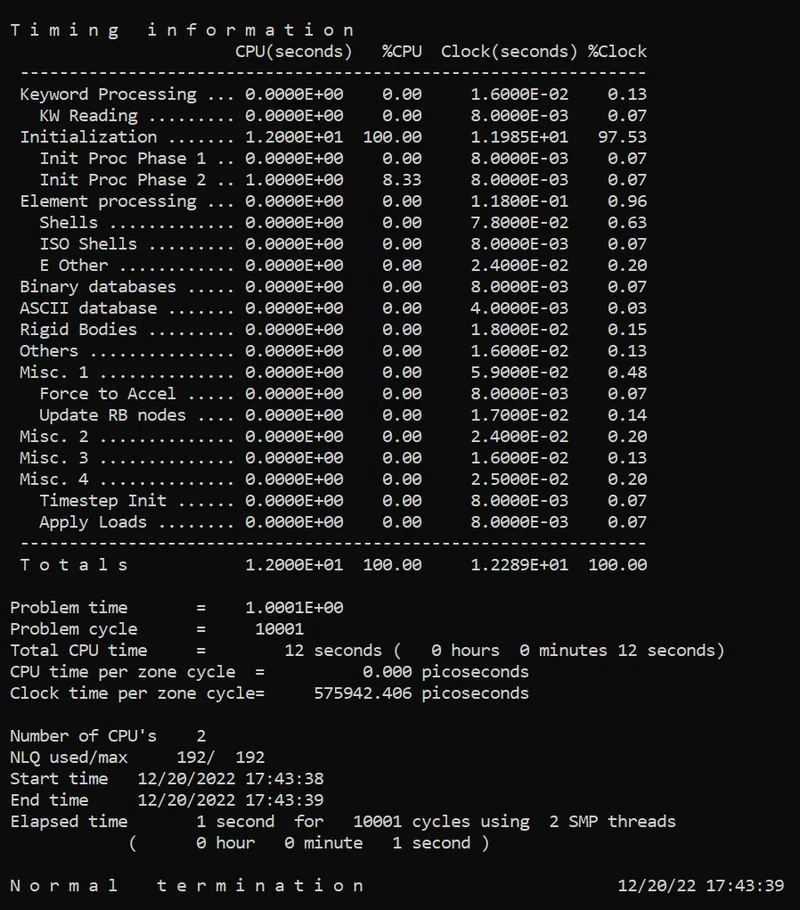
- Title bar > file > run LS-dyna > runned the k file of revolute_joint_deformable_bodies > achieved normal temination. it means the model is ready for post processing.
- During simulation run window will popup as shown in picture below,
STEP 2H : POST PROCESSING
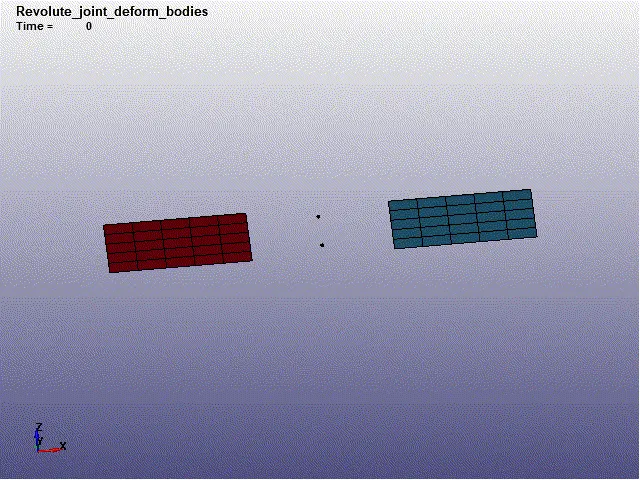
- In order to see simulation results , we have to open output file in LS-Prepost by the following steps.
- In LS-prepost -Title bar > file > open > LS -Dyna binary plot > selected the d3 plot file > visibled to see animation file.
CASE 3 : Creation of Spherical joints between rigid bodies.
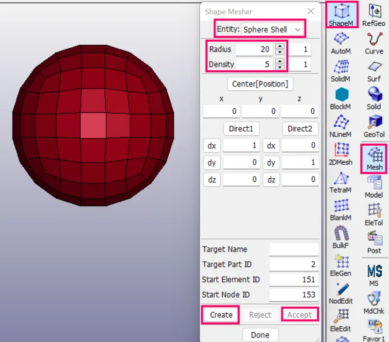
STEP 3A(1) : Creation of inner spherical shell
- To create the inner spherical shell by the following steps.
- Open LS-PrePost, using options under Element and Mesh > Shape Mesher > Entity >Sphere Shell >radius =20 , density=5 > create > accept and done.
STEP 3A(2) : Creation of outter spherical shell
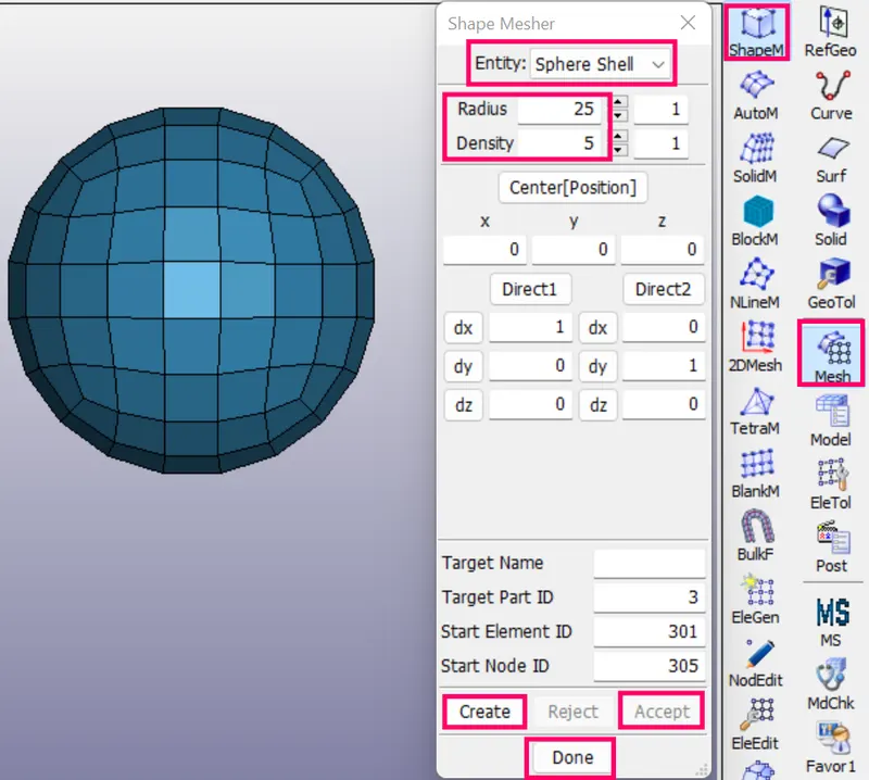
- To create the outter spherical shell by the following steps.
- Open LS-PrePost, using options under Element and Mesh > Shape Mesher > Entity >Sphere Shell >radius =25 , density=5 > create > accept and done.
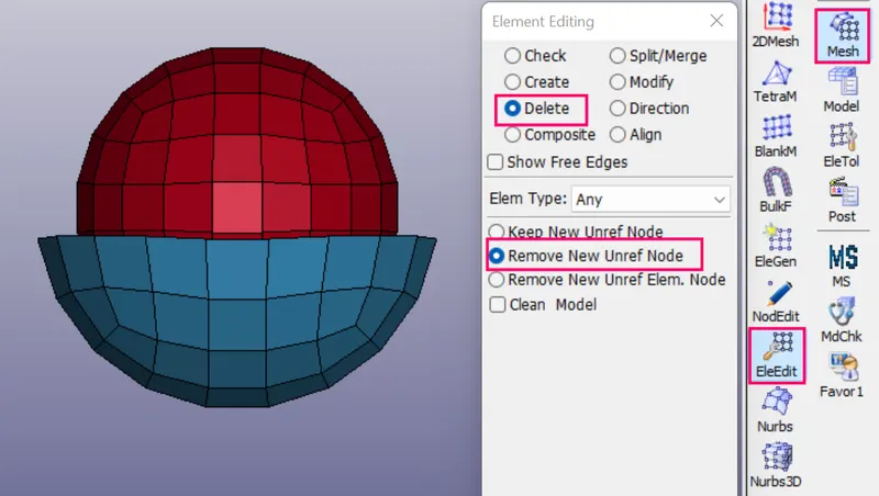
STEP 3A(3) : Deletion of half portion of outter spherical shell
- The elements of the outer sphere shell are deleted using option Element editing to get the necessary shape.
- Mesh > elemet edit > delete > selected the hapf portion of the outter sphere shell elements by pick > done.
STEP 3B : Creation of material card for 2 spherical shell bodies.
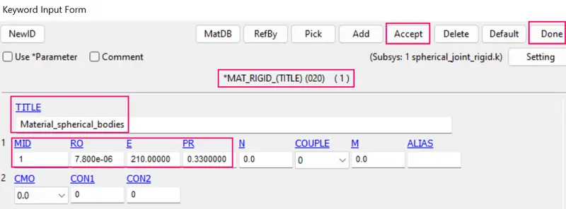
1. To create the material card for 2 spherical shell bodies by the following steps.
2. I had prefereed to choose material type is MAT_RIGID_020
3. This is Material 20. Parts made from this material are considered to belong to a rigidbody.
4. Side bar > model and part > keyword manager > MAT > all > MAT_RIGID_020.
5. Created new ID is 1 and give title is Material_spherical_bodies and specified the properties value as Kg-mm-ms unit system.
STEP 3C : Creation of section card for 2 spherical shell bodies.
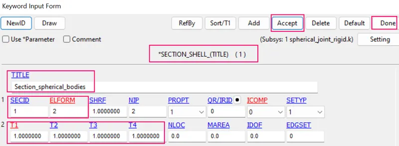
1. In this section element formulation ,integration rule ,nodal thickness and cross sectional properties are defined.
2. Side bar > model and part > keyword manager >all > section >specified the thickness value is 1.0 mm > accept and done.
STEP 3D : Assign the material card and section card to the spherical part.
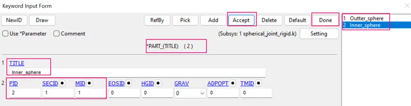
1. Inorder to create the rigid bodies shell part by the following steps.
2. Side bar > model and part > keyword manager >model > part > assigned the MID and SECID cards to tyhe spherical part >accept and done.
STEP 3E : Creation of spherical joint between two spherical rigid bodies using *CONSTRAINED_EXTRA_NODES:
STEP 3E1 : Creation of extra nodes .
- Create two extra nodes manually which are further needed to be associated with two spherical parts for making a spherical joint.
- Create nodes by Element Tools > Node Editing > create > give distinct node IDs for 1st node > Node ID -701 > Node coordinates -(0,0,0) > create > acccept > done.
- Similarly for second node by Element Tools > Node Editing > create > give distinct node IDs for 1st node > Node ID -702 > Node coordinates -(0,0,0) > create > acccept > done.
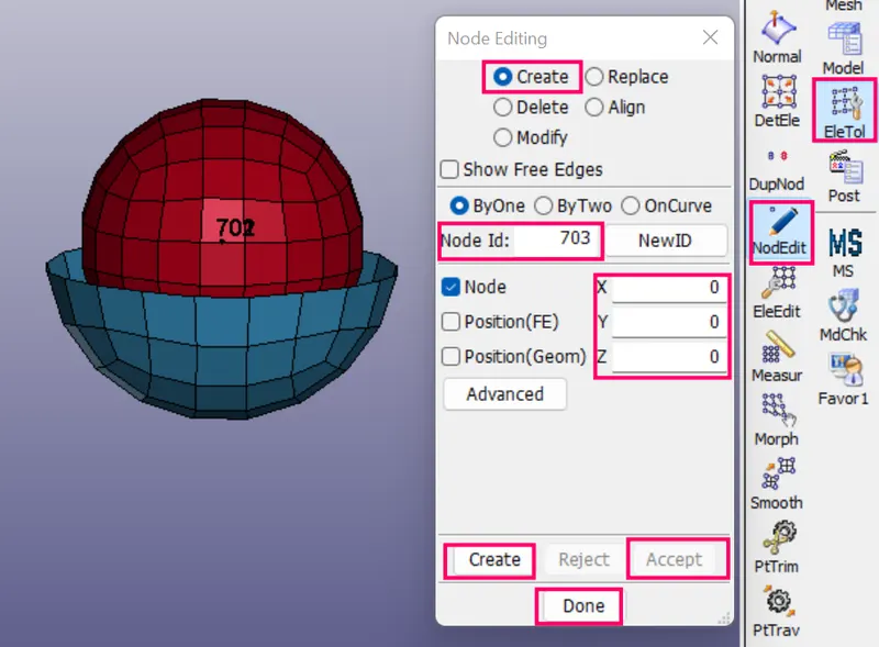
STEP 3E2 : To Associate the extra nodes to respective parts by *CONSTRAINED_EXTRA_NODES_SET
- These newly created nodes are in the space and do not belong to any of the parts now. So, for associating these nodes with part 1 & 2, *CONSTRAINED_EXTRA_NODES_NODE is used.
- That node 701 belong to outter sphere and nodes 702 belong to inner sphere.
- Sidebar > keyword manager > model > all > constrained > CONSTRAINED_EXTRA_NODES_NODE > assigned pid -1> assigned NSID -701 outter sphere part > accept and done.
- Sidebar > keyword manager > model > all > constrained > CONSTRAINED_EXTRA_NODES_NODE > assigned pid -2 > assigned NSID -702 inner sphere part > accept and done.
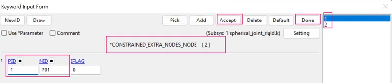
STEP 3E3 : Creation of *CONSTRAINED_JOINT_SPHERICAL card .
- Now, the spherical joint is defined by using *CONSTRAINED_JOINT_SPHERICAL keyword. 2 nodes should be defined to create a spherical joint.
- N1 belong to outter sphere and N2 belong to inner sphere. So, N1=701, N2=702 are defined in the keyword.
- Sidebar > keyword manager > model > all > constrained > CONSTRAINED_JOINT_SPHERICAL > JID-1 > Title is Spherical_joint_rigid_bodies > assigned the node ids N1=701, N2=702 > accept and done.
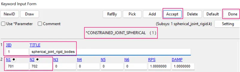
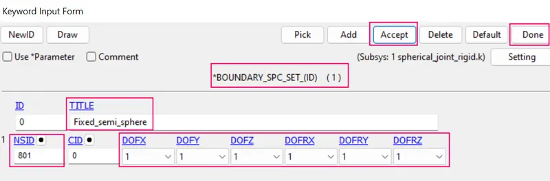
STEP 3E4 : Define a boundary condition (SPC) for outter semi sphere.
- Fixed the nodes of semi sphere is constrained in the X,Y&Z direction .
- Inorder to create single point constrain by the following steps .
- Sidebar > model > create entity > boundary > spc > create > selected the node by part > nodes at the fixed end is constrained in both translational and rotational X,Y & Z direction > apply and done.
- Checked created SPC in shell part 1 in keyword manager.
- Sidebar > keyword manager > model >Boundary > SPC_SET > checked assigned the node set id > accept and done.
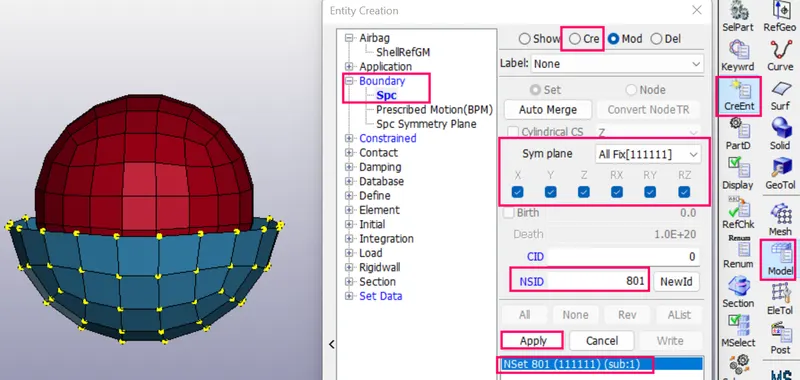
STEP 3E5: Define the initial velocity to the inner sphere.
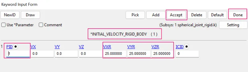
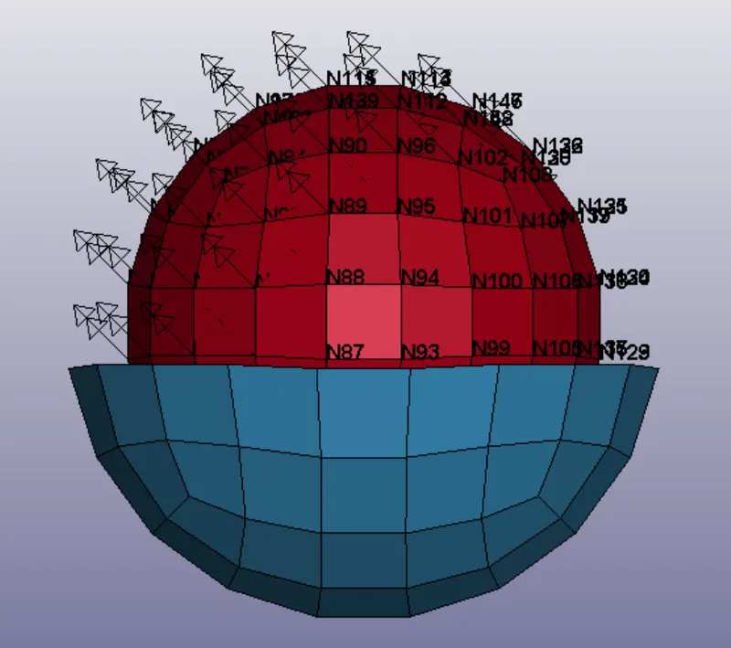
- Initial Velocity is assigned to the Inner Sphere By INITIAL_VELOCITY_RIGID_BODY, with rotational velocities in the X, Y, Z axis.
- In order to define the initial velocity by the following steps.
- Sidebar > model > keywordmanager > all > INITIAL > VELOCITY_RIGID_BODY > assigned PID-1 (for inner sphere) > rotational velocity about X, Y & Z axis -25mm/ms > accept and done.
STEP 3F1 : Define a control time step card.
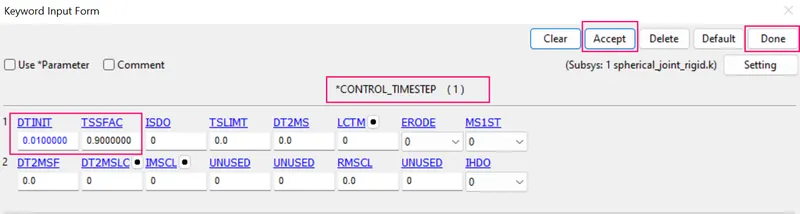
- In order to create control timestep card by the following steps.
- Sidebar > keywordmanager > all > control > timestep >TSSFAC-0.9 > DT-initial-0.01 ms > accept and done.
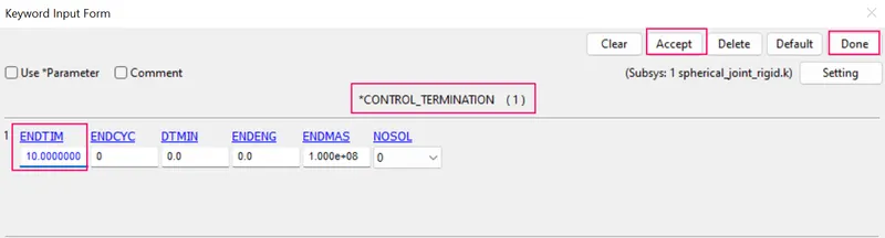
STEP 3F2 : Define a control termination card.
1. The main purpose of control termination card is to stop the job.
2. In order to assign the control termination card by the following steps.
3. Side bar > model and part > keyword manager > control > termination > specify termination time is 10 ms > accept and done.
STEP 3G :Define the output database as Binary D3 plot.
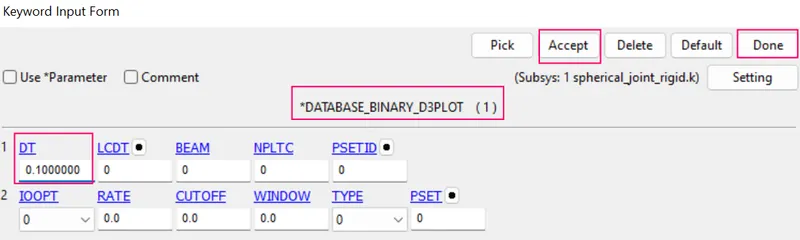
- DATABASE_BINARY_D3PLOT ensures d3 plot files which its stores stress strain contour of the entire deformed model.
- In order to create the DATABASE_BINARY_D3PLOT by the fllowing steps.
- Side bar > model and part > keyword manager > database > select DATABASE_BINARY_D3PLOT > DT value is 0.1 ms is a time interval between output states > accept & done.
STEP 3H: Model checkup
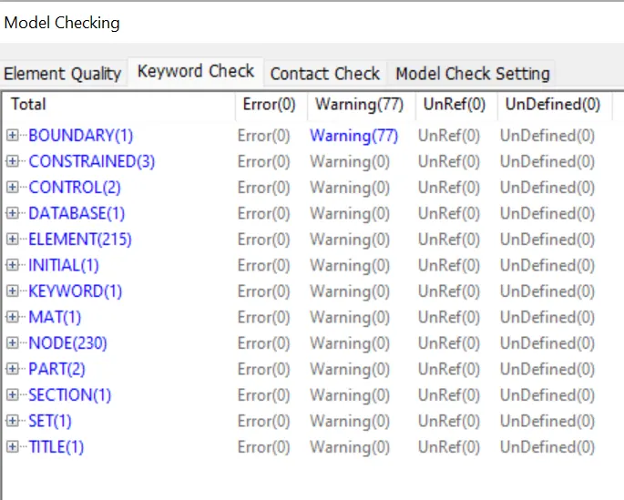
- The model is checked for any errors before solving using model checker.
- After all the errors are cleared, the drop test setup is saved and is ready to run in LS DYNA manager for solving the scenario.
- Warnings we can ignore ,once model check is run , it will look like as shown in picture below
STEP 3I : Run the Simulation of Spherical joint between rigid bodies
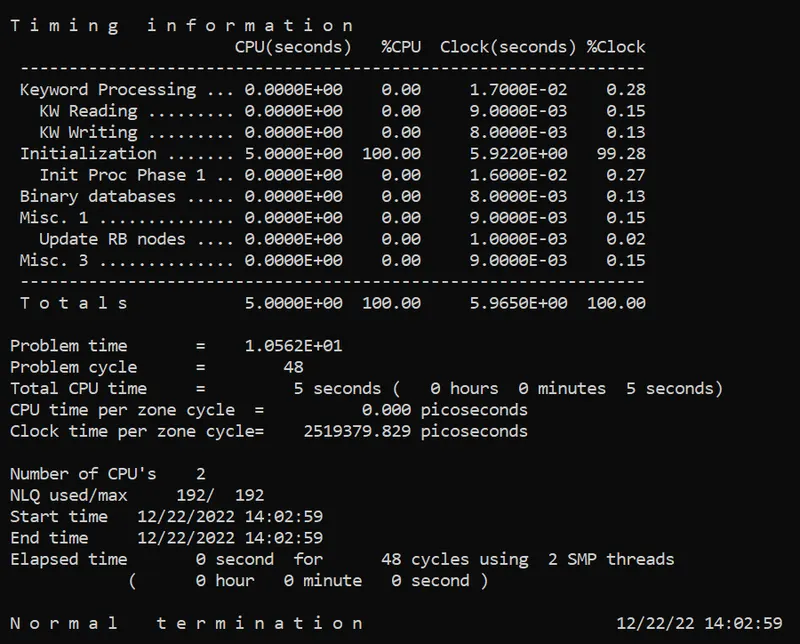
- To run the using LS-run by the following steps.
- Title bar > file > run LS-dyna > runned the k file of Spherical_joint_rigid_bodies > achieved normal temination. it means the model is ready for post processing.
- During simulation run window will popup as shown in picture below,
STEP 3J : POST PROCESSING
- In order to see simulation results , we have to open output file in LS-Prepost by the following steps.
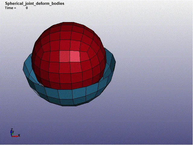
- In LS-prepost -Title bar > file > open > LS -Dyna binary plot > selected the d3 plot file > visibled to see animation file.
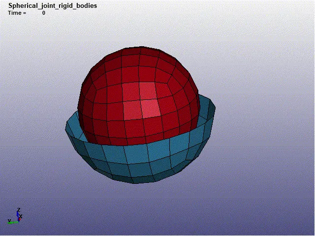
CASE 4 : Creation of spherical joint between deformable bodies.
- In this case same FE shell model used as previous case1.
- Delete other keywords and saved as a spherical_joint_deformable_bodies.K file.
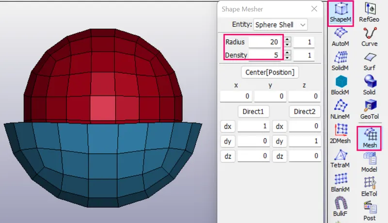
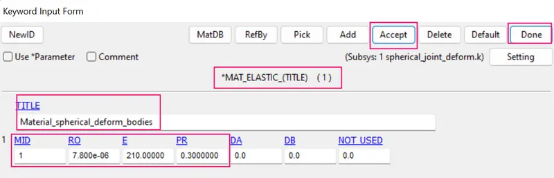
STEP 4A : Creation of material card for 2 spherical shell bodies.
1. To create the material card for 2 spherical shell bodies by the following steps.
2. I had prefereed to choose material type is MAT_ELASTC_001
3. This is Material Type 1. This is an isotropic hypoelastic material and is available for beam, shell, and solid elements in LS-DYNA
4. Side bar > model and part > keyword manager > MAT > all > MAT_ELASTC_001
5. Created new ID is 1 and give title is Material_spherical_bodies and specified the properties value as Kg-mm-ms unit system.
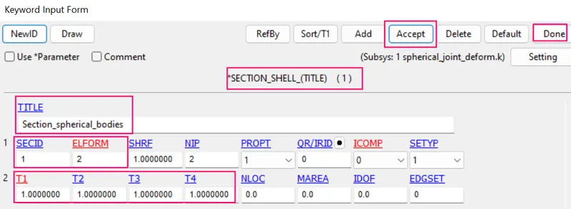
STEP 4B : Creation of section card for 2 spherical shell bodies.
1. In this section element formulation ,integration rule ,nodal thickness and cross sectional properties are defined.
2. Side bar > model and part > keyword manager >all > section >specified the thickness value is 1.0 mm > accept and done.
STEP 4C : Assign the material card and section card to the spherical part.
1. Inorder to create the rigid bodies shell part by the following steps.
2. Side bar > model and part > keyword manager >model > part > assigned the MID and SECID cards to the spherical part >accept and done.
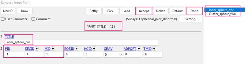
STEP 4D : Creation of revolute joint between two deformable bodies using *CONSTRAINED_NODAL_RIGID_BODY(CNRB).
STEP 4D1 : To Associate extra nodes to respective parts by *CONSTRAINED NODAL RIGID BODY (CNRB)
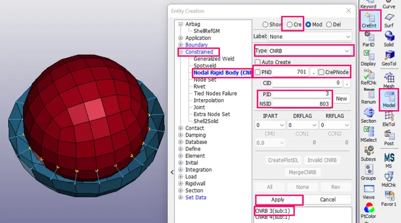
- Create Entity > Constrained > Nodal Rigid Body(CNRB) > Create.
- Toggle off the CrePNode option which will disable the creation of PNODE at the mass center of selected nodes.
- Now specify the PND is 701 node as the first point followed by inner sphere outter circumference nodes slected by path and hit apply option.
- A CNRB(3) will be created with PNODE at the 701 node position.
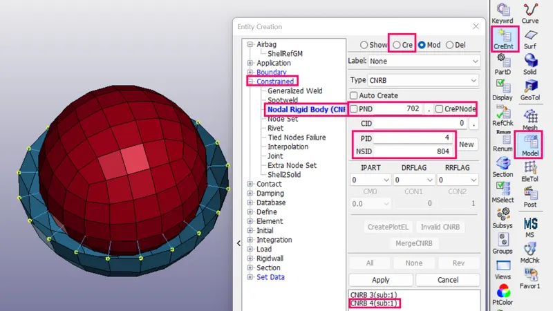
- Similarly,Now specify the PND is 702 node as the first point followed by outter sphere edge nodes slected by path and hit apply option.
- A CNRB(4) will be created with PNODE at the 702 node position.
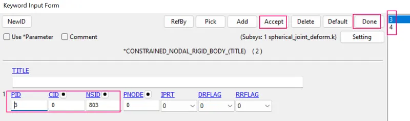
- Checked the constrained nodal rigid body in keywordmanager.
- Sidebar> model > keywordmanager > constrained > Nodal rigid body > assigned NSID-803 > accept and done.
STEP 4D2 : Creation of CONSTRAINED_JOINT_SPHERICAL card .
- Now, the spherical joint is defined by using *CONSTRAINED_JOINT_SPHERICAL keyword. 2 nodes should be defined to create a spherical joint.
- N1 belong to outter sphere and N2 belong to inner sphere. So, N1=701, N2=702 are defined in the keyword.
- Sidebar > keyword manager > model > all > constrained > CONSTRAINED_JOINT_SPHERICAL > JID-1 > Title is Spherical_joint_rigid_bodies > assigned the node ids N1=701, N2=702 > accept and done.
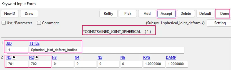
STEP 4E : Define a boundary condition (SPC) for outter semi sphere.
- Fixed the nodes of semi sphere is constrained in the X,Y&Z direction .
- Inorder to create single point constrain by the following steps .
- Sidebar > model > create entity > boundary > spc > create > selected the node by part > nodes at the fixed end is constrained in both translational and rotational X,Y & Z direction > apply and done.
- Checked created SPC in shell part 1 in keyword manager.
- Sidebar > keyword manager > model >Boundary > SPC_SET > checked assigned the node set id > accept and done.
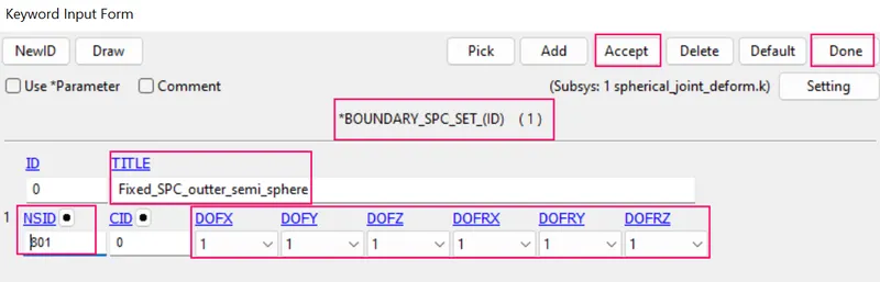
STEP 4F : Define the initial velocity to the inner sphere.
STEP 4F1 : Creation of Nodeset for the inner sphere.
- Before define the initial velocity we have to create the Nodeset for inner sphere.
- In order to create the NODESET bt the following steps.
- Sidebar > model > create > SETID-805 > selected the nodes of the inner sphere by part > apply > done.
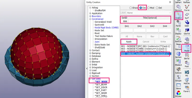
STEP 4F2 : Define the initial velocity to the inner sphere.
- Initial Velocity is assigned to the Inner Sphere By INITIAL_VELOCITY with rotational velocities in the X, Y, Z axis.
- In order to define the initial velocity by the following steps.
- Sidebar > model > keywordmanager > all > INITIAL > VELOCITY > assigned NSID-805 (for inner sphere) > rotational velocity about X, Y & Z axis is 25mm/ms > accept and done.
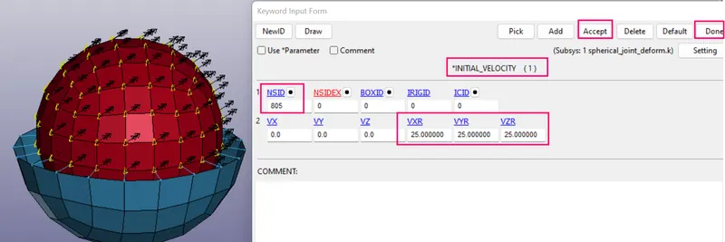
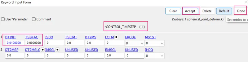
STEP 4G : Define a control time step card.
- In order to create control timestep card by the following steps.
- Sidebar > keywordmanager > all > control > timestep >TSSFAC-0.9 > DT-initial-0.01 ms > accept and done.
STEP 4H : Define a control termination card.
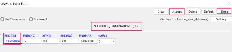
1. The main purpose of control termination card is to stop the job.
2. In order to assign the control termination card by the following steps.
3. Side bar > model and part > keyword manager > control > termination > specify termination time is 10 ms > accept and done.
STEP 4I :Define the output database as Binary D3 plot.
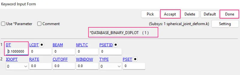
- DATABASE_BINARY_D3PLOT ensures d3 plot files which its stores stress strain contour of the entire deformed model.
- In order to create the DATABASE_BINARY_D3PLOT by the fllowing steps.
- Side bar > model and part > keyword manager > database > select DATABASE_BINARY_D3PLOT > DT value is 0.1 ms is a time interval between output states > accept & done.
STEP 4J: Model checkup
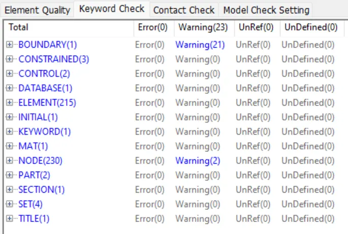
- The model is checked for any errors before solving using model checker.
- After all the errors are cleared, the drop test setup is saved and is ready to run in LS DYNA manager for solving the scenario.
- Warnings we can ignore ,once model check is run , it will look like as shown in picture below
STEP 4K : Run the Simulation of Spherical joint between rigid bodies
- To run the using LS-run by the following steps.
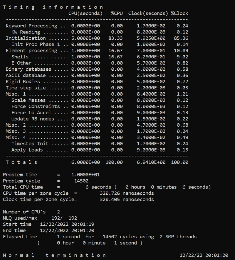
- Title bar > file > run LS-dyna > runned the k file of Spherical_joint_deformable_bodies > achieved normal temination. it means the model is ready for post processing.
- During simulation run window will popup as shown in picture below,
STEP 4L : POST PROCESSING
- In order to see simulation results , we have to open output file in LS-Prepost by the following steps.
- In LS-prepost -Title bar > file > open > LS -Dyna binary plot > selected the d3 plot file > visibled to see animation file.
CASE 5 : Creation of cylindrical joints between rigid bodies.
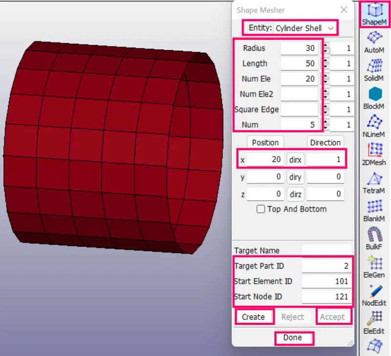
STEP 5A1 : Creation of Outter cylindrical shell.
- First, two separate shell elements are created by using the following steps,
- Side bar > mesh > Element and Mesh > Shape Mesher > Select the entity as cylinder shell > radius-30mm,length=50mm ,No of elements along the circumference of the cylinder =20 and No of elements along the length of the cylinder=5 > cylinder node position X=20 and dirX=1 > create > accept and done.
STEP 5A2 : Creation of inner cylindrical shell.
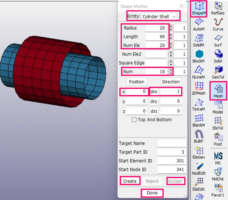
- First, two separate shell elements are created by using the following steps,
- Side bar > mesh > Element and Mesh > Shape Mesher > Select the entity as cylinder shell > radius-20mm,length=90mm, No of elements along the circumference of the cylinder =20 and No of elements along the length of the cylinder=10 > cylinder node position X=0 and dirX=1 > create > accept and done.
STEP 5 B : Creation of material card for outter and inner cylindrical shell
1. To create the material card for 2 shell bodies by the following steps.
2. I had prefereed to choose material type is MAT_RIGID_020
3. This is Material 20. Parts made from this material are considered to belong to a rigidbody.
4. Side bar > model and part > keyword manager > MAT > all > MAT_RIGID_020.
5. Created new ID is 1 and give title is Material_revolution_joint and specified the properties value as Kg-mm-ms unit system.
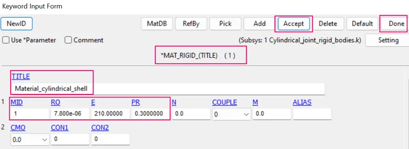
Where,
- RO- density of a steel = 7.8 * 10⁻⁶ Kg /mm³.
- E-Youngs modulus = 210 kg / mm ms²
- PR-Poissons ratio= 0.30.
STEP 5C : Creation of section card for for outter and inner cylindrical shell
1. In this section element formulation ,integration rule ,nodal thickness and cross sectional properties are defined.
2. Side bar > model and part > keyword manager >all > section >specified the thickness value is 1.0 mm > accept and done.
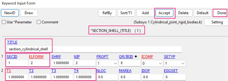
STEP 5D : Assign the material card and section card to the rigid bodies part.
1. Inorder to create the rigid bodies cylindrical shell part by the following steps.
2. Side bar > model and part > keyword manager >model > part > assigned the MID and SECID cards to rigid bodies part >accept and done.
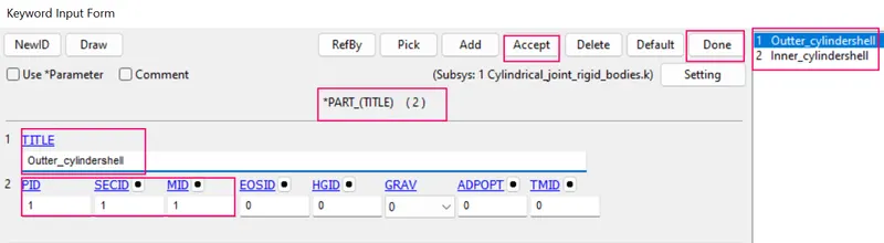
STEP 5E : Creation of cylindrical joint between two rigid bodies using *CONSTRAINED_EXTRA_NODES:
STEP 5E1 : Creation of extra nodes between two rigid bodies.
- Create four extra nodes manually which are further needed to be associated with two parts for making a cylindrical joint.
- Create nodes by Element Tools > Node Editing > create > give distinct node IDs for 1st node > Node ID -401 > Node coordinates -(30,0) > create > acccept > done.
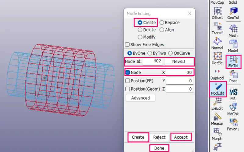
- Similarly Create 2nd node by Element Tools > Node Editing > create > give distinct node IDs for 2nd node > Node ID -402 > Node coordinates -(60,0) > create > acccept > done.
- Create 3rd node by Element Tools > Node Editing > create > give distinct node IDs for 3rd node > Node ID -403 > Node coordinates -(30,0) > create > acccept > done.
- Create 4th node by Element Tools > Node Editing > create > give distinct node IDs for 4th node > Node ID -404 > Node coordinates -(30,0) > create > acccept > done.
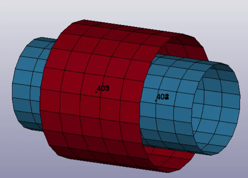
STEP 5E2 : Creation of node set for created extra nodes between two bodies.
Creation of First Nodeset
- Create new node sets, where nodes 401 and 403 belong to one node-set, and nodes 402 and 404 belong to another node-set. *SET_NODE_LIST keyword.
- Sidebar > create entity > SET DATA > SET NODE > selected the node ID 401 and 403 > give NSID-501 > title is Nodeset_one > apply > done.
- Checked the created node sets can through Sidebar > model > keyword manger > SET > NODE LIST > title as Nodeset_one > SID-501 > assigned the node IDs 401 and 403 > Created nodeset for that nodes > accept and done.
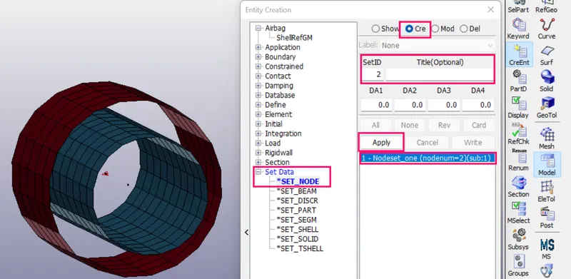
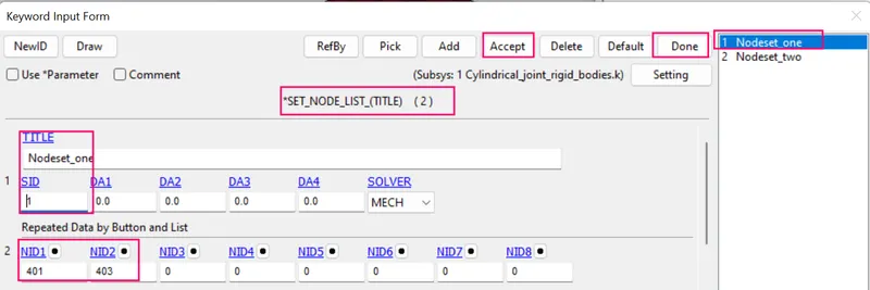
Creation of second Nodeset
- Sidebar > create entity > SET DATA > SET NODE > selected the node ID 402 and 404 > give NSID-502 > title is Nodeset_two > apply > done.
- Checked the created node sets can through Sidebar > model > keyword manger > SET > NODE LIST > title as Nodeset_two > SID-501 > assigned the node IDs 402 and 404 > Created nodeset for that nodes > accept and done.
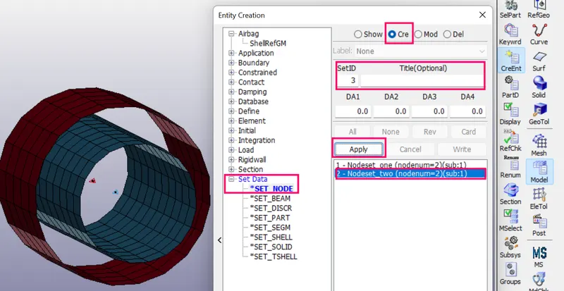
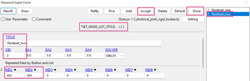
STEP 5E3 : To Associate the extra nodes to respective parts by *CONSTRAINED_EXTRA_NODES_SET
- These newly created nodes are in the space and do not belong to any of the parts now. So, for associating these nodes with part 1 and part 2, *CONSTRAINED_EXTRA_NODES_SET is used.
- That nodes 401 and 403 belong to part 1 and nodes 402 and 404 belong to part 2.
- Sidebar > keyword manager > model > all > constrained > CONSTRAINED_EXTRA_NODES_SET > set pid -1> assigned NSID -501 first shell part > accept and done.
- Sidebar > keyword manager > model > all > constrained > CONSTRAINED_EXTRA_NODES_SET > set pid-2 > assigned NSID -502 second shell part > accept and done.
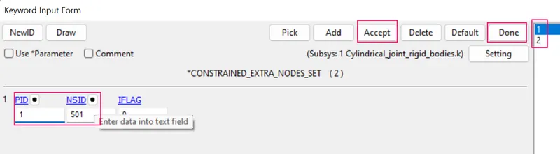
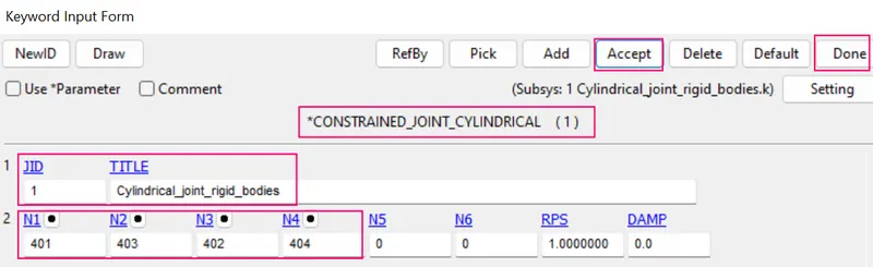
STEP 5E4 : Creation of *CONSTRAINED_JOINT_CYLINDRICAL card .
- Now, the cylindrical joint is defined by using *CONSTRAINED_JOINT_CYLINDRICAL keyword. Four nodes should be defined to create a revolute joint. N1 and N3 belong to body 1 and N2 and N4 belong to body 2. So, N1=401, N2=403, N3=402, and N4=404 are defined in the keyword.
- Sidebar > keyword manager > model > all > constrained > CONSTRAINED_JOINT_CYLINDRICAL > JID-1 > Title is Cylindrical_joint_rigid > assigned the node ids N1=401, N2=403, N3=402, and N4=404 > accept and done.
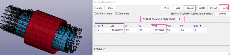
STEP 5E5 : Define the initial velocity to the inner cylinder.
- Initial Velocity is assigned to the Inner cylinder By INITIAL_VELOCITY_RIGID_BODY, with rotational velocities in the X, Y, Z axis.
- In order to define the initial velocity by the following steps.
- Sidebar > model > keywordmanager > all > INITIAL > VELOCITY_RIGID_BODY > assigned PID-2 (for inner cylinder) > initial translational velocity in x-directionis 10 mm/ms , Initial rotational velocity about the x-axis is 10 mm/ms > accept and done.
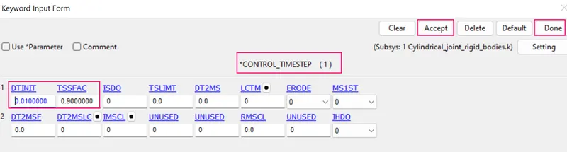
STEP 5F1 : Define a control time step card.
- In order to create control timestep card by the following steps.
- Sidebar > keywordmanager > all > control > timestep >TSSFAC-0.9 > DT-initial-0.01 ms > accept and done.
STEP 5F2 : Define a control termination card.
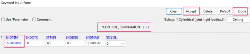
1. The main purpose of control termination card is to stop the job.
2. In order to assign the control termination card by the following steps.
3. Side bar > model and part > keyword manager > control > termination > specify termination time is 5 ms > accept and done.
STEP 5G : Define the output database as Binary D3 plot.
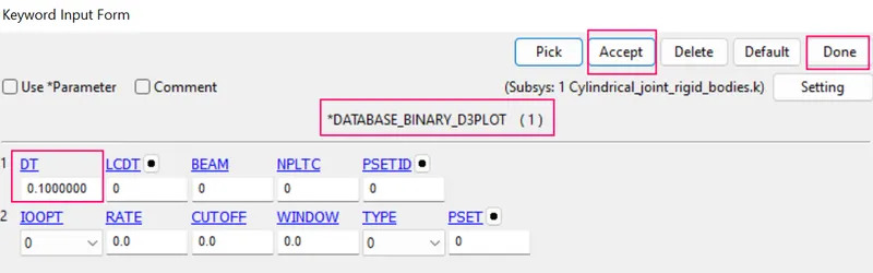
- DATABASE_BINARY_D3PLOT ensures d3 plot files which its stores stress strain contour of the entire deformed model.
- In order to create the DATABASE_BINARY_D3PLOT by the fllowing steps.
- Side bar > model and part > keyword manager > database > select DATABASE_BINARY_D3PLOT > DT value is 0.1 ms is a time interval between output states > accept & done.
STEP 5H: Model checkup
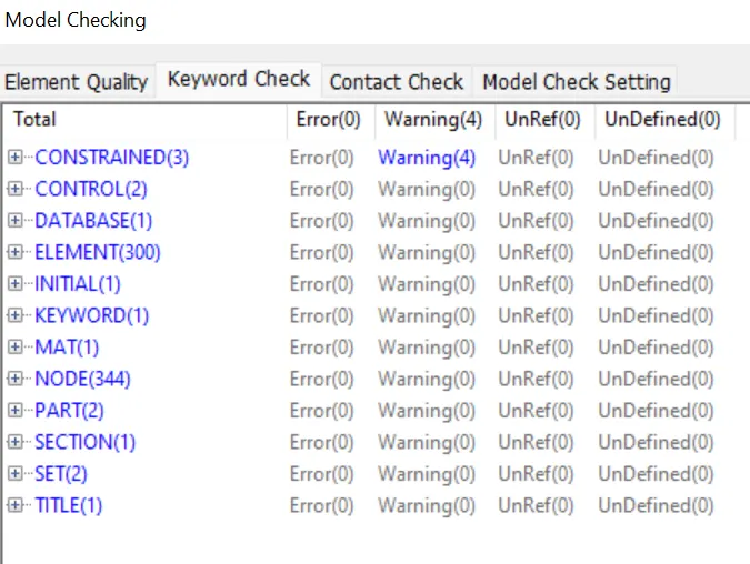
- The model is checked for any errors before solving using model checker.
- After all the errors are cleared,and is ready to run in LS DYNA manager for solving the scenario.
- Warnings we can ignore ,once model check is run , it will look like as shown in picture below
STEP 5I : Run the Simulation of cylindrical joint between rigid bodies
- To run the using LS-run by the following steps.
- Title bar > file > run LS-dyna > runned the k file of Cylindrical_joint_rigid_bodies > achieved normal temination. it means the model is ready for post processing.
- During simulation run window will popup as shown in picture below,
STEP 5J : POST PROCESSING
- In order to see simulation results , we have to open output file in LS-Prepost by the following steps.
- In LS-prepost -Title bar > file > open > LS -Dyna binary plot > selected the d3 plot file > visibled to see animation file.
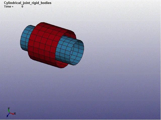
CASE 6 : Creation of cylindrical joints between deformable bodies.
Cylindrical geometry used as in the previous case(5)
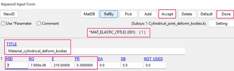
STEP 6A : Creation of material card for 2 cylindrical shell bodies.
1. To create the material card for 2 cylindrical shell bodies by the following steps.
2. I had prefereed to choose material type is MAT_ELASTC_001
3. This is Material Type 1. This is an isotropic hypoelastic material and is available for beam, shell, and solid elements in LS-DYNA
4. Side bar > model and part > keyword manager > MAT > all > MAT_ELASTC_001
5. Created new ID is 1 and give title is Material_cylindrical_rigid_bodies and specified the properties value as Kg-mm-ms unit system.
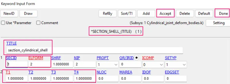
STEP 6B : Creation of section card for 2 spherical shell bodies.
1. In this section element formulation ,integration rule ,nodal thickness and cross sectional properties are defined.
2. Side bar > model and part > keyword manager >all > section >specified the thickness value is 1.0 mm > accept and done.
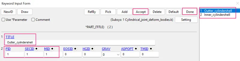
STEP 6C : Assign the material card and section card to the cylindrical part.
1. Inorder to create the rigid bodies shell part by the following steps.
2. Side bar > model and part > keyword manager >model > part > assigned the MID and SECID cards to the cylindrical part >accept and done.
STEP 6D : Creation of cylindrical joint between two deformable bodies using *CONSTRAINED_NODAL_RIGID_BODY(CNRB).
STEP 6D1 : To Associate extra nodes to respective parts by *CONSTRAINED NODAL RIGID BODY (CNRB)
- Create Entity > Constrained > Nodal Rigid Body(CNRB) > Create.
- Toggle off the CrePNode option which will disable the creation of PNODE at the mass center of selected nodes.
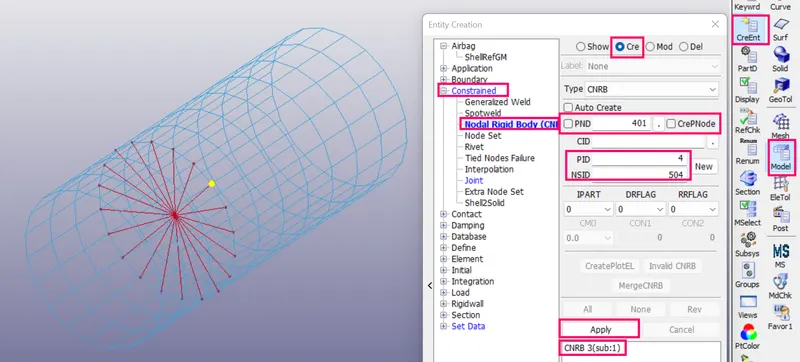
- Now specify the PND is 401 node as the first point followed by inner cylinder outter circumference nodes selected by path and hit apply option.
- A CNRB(3)will be created with PNODE at the 401 node position.
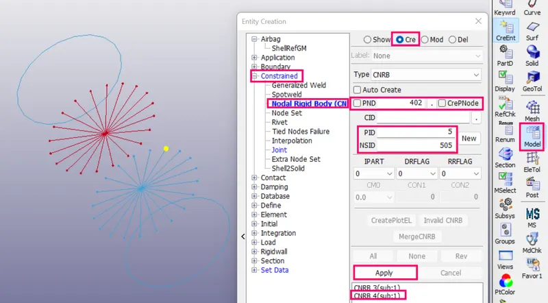
- Now specify the PND is 402 node as the first point followed by inner cylinder outter circumference nodes selected by path and hit apply option.
- A CNRB(4)will be created with PNODE at the 402 node position.
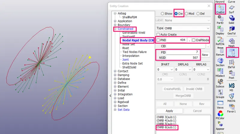
- Now specify the PND is 403 node as the first point followed by inner cylinder outter circumference nodes selected by path and hit apply option.
- A CNRB(5)will be created with PNODE at the 403 node position.
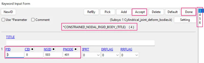
- Now specify the PND is 404 node as the first point followed by inner cylinder outter circumference nodes selected by path and hit apply option.
- A CNRB(6)will be created with PNODE at the 404 node position.
- Checked the constrained nodal rigid body in keywordmanager.
- Sidebar> model > keywordmanager > constrained > Nodal rigid body > assigned NSID-503 > accept and done.
STEP 6D2 : Creation of *CONSTRAINED_JOINT_CYLINDRICAL card .
- Now, the spherical joint is defined by using *CONSTRAINED_JOINT_CYLINDRICAL keyword. 2 nodes should be defined to create a spherical joint.
- N1 and N3 belong to body 1 and N2 and N4 belong to body 2. So, N1=401, N2=403, N3=402, and N4=404 are defined in the keyword.
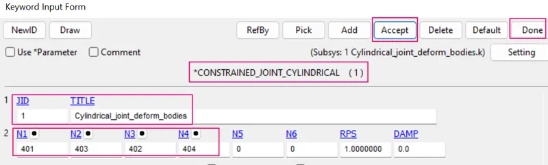
- Sidebar > keyword manager > model > all > constrained > CONSTRAINED_JOINT_CYLINDRICAL > JID-1 > Title is cylindrical_joint_deform_bodies > assigned the node ids N1=401, N2=403, N3=402, and N4=404 > accept and done.
STEP 6E : Define the initial velocity to the inner cylinder.
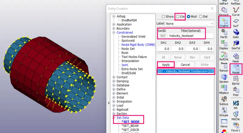
STEP 6E1 : Creation of Nodeset for the inner cylinder.
- Before define the initial velocity we have to create the Nodeset for inner cylinder.
- In order to create the NODESET bt the following steps.
- Sidebar > model > create entity > SETDATA >SETNODE > SETID-507 > selected the nodes of the inner cylinder by part > apply > done.
STEP 6E2 : Define the initial velocity to the inner Cylinder
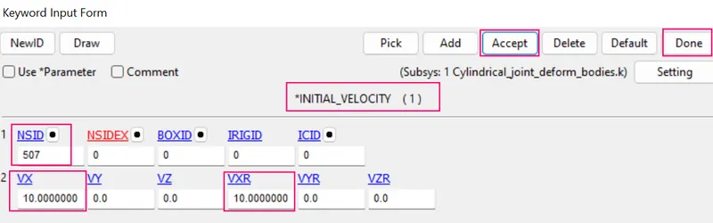
- Initial Velocity is assigned to the Inner cylinder By INITIAL_VELOCITY with rotational velocities in the X, Y, Z axis.
- In order to define the initial velocity by the following steps.
- Sidebar > model > keywordmanager > all > INITIAL > VELOCITY > assigned NSID-507 (for inner cylinder) > initial translational velocity in x-directionis 10 mm/ms > Initial rotational velocity about the x-axis is 10 mm/ms > accept and done.
STEP 6F1 : Define a control time step card.
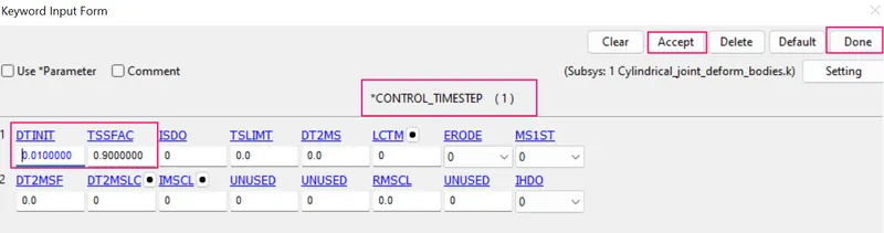
- In order to create control timestep card by the following steps.
- Sidebar > keywordmanager > all > control > timestep >TSSFAC-0.9 > DT-initial-0.01 ms > accept and done.
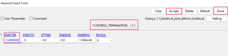
STEP 6F2 : Define a control termination card.
1. The main purpose of control termination card is to stop the job.
2. In order to assign the control termination card by the following steps.
3. Side bar > model and part > keyword manager > control > termination > specify termination time is 5 ms > accept and done.
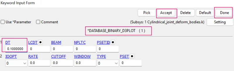
STEP 6G : Define the output database as Binary D3 plot.
- DATABASE_BINARY_D3PLOT ensures d3 plot files which its stores stress strain contour of the entire deformed model.
- In order to create the DATABASE_BINARY_D3PLOT by the fllowing steps.
- Side bar > model and part > keyword manager > database > select DATABASE_BINARY_D3PLOT > DT value is 0.1 ms is a time interval between output states > accept & done.
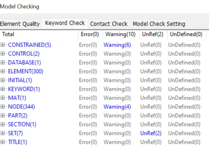
STEP 6H: Model checkup
- The model is checked for any errors before solving using model checker.
- After all the errors are cleared,and is ready to run in LS DYNA manager for solving the scenario.
- Warnings we can ignore ,once model check is run , it will look like as shown in picture below
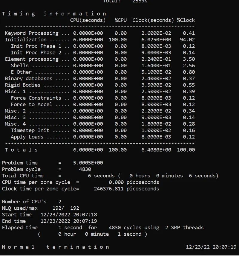
STEP 6I : Run the Simulation of cylindrical joint between rigid bodies
- To run the using LS-run by the following steps.
- Title bar > file > run LS-dyna > runned the k file of Cylindrical_joint_deform_bodies > achieved normal temination. it means the model is ready for post processing.
- During simulation run window will popup as shown in picture below,
STEP 6J : POST PROCESSING
- In order to see simulation results , we have to open output file in LS-Prepost by the following steps.
- In LS-prepost -Title bar > file > open > LS -Dyna binary plot > selected the d3 plot file > visibled to see animation file.
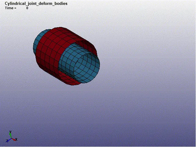
CASE 7 : Creation of translational joint between rigid bodies.
STEP 7A1 : Creation of Box shell1.
- First, two separate box shell elements are created by using the following steps,
- Side bar > mesh > Element and Mesh > Shape Mesher > Select the entity as box shell > Pmax (100,100,100)>Vx=5,Vy=5 & Vz=5 > create > accept and done.
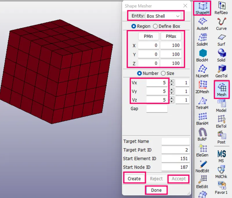
STEP 7A2 : Deleting the elements in Box shell1.
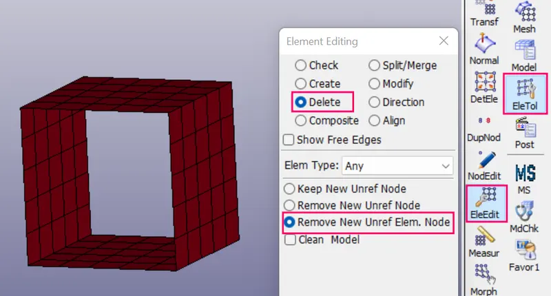
- The elements of the box shell are deleted using option Element editing to get the necessary shape.
- Sidebar > element tool > element edit > delete > selected the elemets of the box1 shell elements by pick > done.
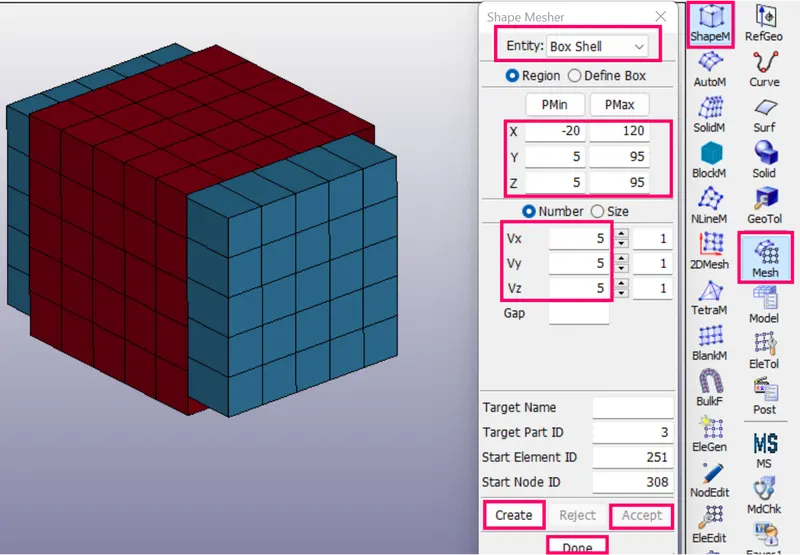
STEP 7A3 : Creation of Box shell2.
- First, two separate box shell elements are created by using the following steps,
- Side bar > mesh > Element and Mesh > Shape Mesher > Select the entity as box shell > specify Pmin & Pmax values >Vx=5,Vy=5 & Vz=5 > create > accept and done.
STEP 7A4 : Deleting the elements in Box shell2.
- The elements of the box shell are deleted using option Element editing to get the necessary shape.
- Sidebar > element tool > element edit > delete > selected the elemets of the box2 shell elements by pick > done.
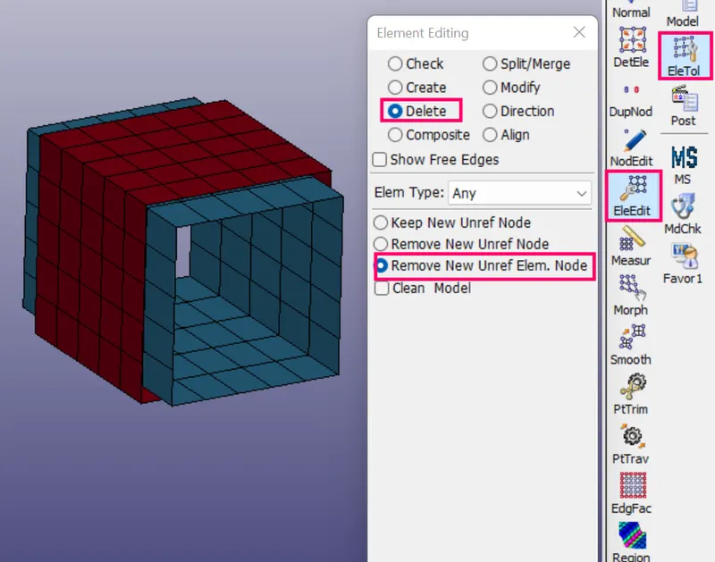
STEP 7B : Creation of material card for outter and inner shell box
1. To create the material card for 2 shell boxes by the following steps.
2. I had prefereed to choose material type is MAT_RIGID_020
3. This is Material 20. Parts made from this material are considered to belong to a rigidbody.
4. Side bar > model and part > keyword manager > MAT > all > MAT_RIGID_020.
5. Created new ID is 1 and give title is Material_rigid_bodies and specified the properties value as Kg-mm-ms unit system.
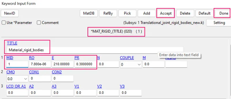
Where,
- RO- density of a steel = 7.8 * 10⁻⁶ Kg /mm³.
- E-Youngs modulus = 210 kg / mm ms²
- PR-Poissons ratio= 0.30.
STEP 7C : Creation of section card for for outter and inner box shell
1. In this section element formulation ,integration rule ,nodal thickness and cross sectional properties are defined.
2. Side bar > model and part > keyword manager >all > section >specified the thickness value is 1.0 mm > accept and done.
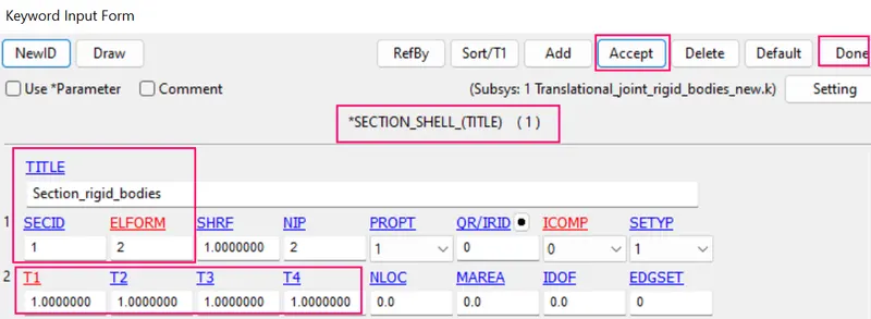
STEP 7D : Assign the material card and section card to the rigid bodies part.
1. Inorder to create the rigid bodies cylindrical shell part by the following steps.
2. Side bar > model and part > keyword manager >model > part > assigned the MID and SECID cards to rigid bodies part >accept and done.
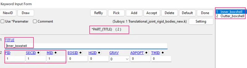
STEP 7E : Creation of translational joint between two rigid bodies using *CONSTRAINED_EXTRA_NODES:
STEP 7E1 : Creation of extra nodes between two bodies.
- Create the six extra nodes manually which are further needed to be associated with two parts for making a translational joint.
- Create node by Element Tools > Node Editing > create > give distinct node IDs for 1st node > Node ID -243 > Node coordinates -(20,60,60) > create > acccept > done.
- Create node by Element Tools > Node Editing > create > give distinct node IDs for 2nd node > Node ID -244 > Node coordinates -(80,60,60) > create > acccept > done.
- Create node by Element Tools > Node Editing > create > give distinct node IDs for 3rd node > Node ID -245 > Node coordinates -(50,30,60) > create > acccept > done.
- Create node by Element Tools > Node Editing > create > give distinct node IDs for 1st node > Node ID -246 > Node coordinates -(20,60,60) > create > acccept > done.
- Create node by Element Tools > Node Editing > create > give distinct node IDs for 2nd node > Node ID -247 > Node coordinates -(80,60,60) > create > acccept > done.
- Create node by Element Tools > Node Editing > create > give distinct node IDs for 3rd node > Node ID -248 > Node coordinates -(50,30,60) > create > acccept > done.
- Two pairs of nodes are created 243-246 and 244-247 which is coincident and collinear. The third pair 245-248 is coincident and slightly away from the axis of the other two pairs but in between the two pairs.
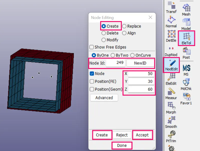
STEP 7E2 : Creation of node set for created extra nodes between two rigid bodies.
Creation of First Nodeset
- Create new node sets, where nodes 243,244 & 245 belong to one node-set, and nodes 246,247 & 248 belong to another node-set in *SET_NODE_LIST keyword.
- Sidebar > create entity > SET DATA > SET NODE > selected the node IDs 243,244 & 245 > give NSID-1 > title is Nodeset_one > apply > done.
- Checked the created node sets can through Sidebar > model > keyword manger > SET > NODE LIST > title as Nodeset_one > SID-1 > assigned the node IDs 243,244 & 245 > Created nodeset for that nodes > accept and done.
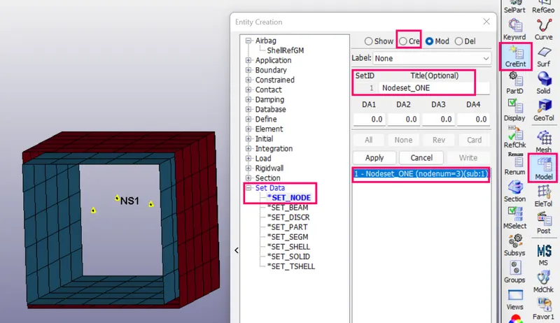
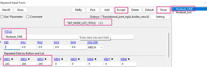
Creation of second Nodeset
- Sidebar > create entity > SET DATA > SET NODE > selected the node IDs 246,247 & 248 > give NSID-2 > title is Nodeset_two > apply > done.
- Checked the created node sets can through Sidebar > model > keyword manger > SET > NODE LIST > title as Nodeset_two > SID-2 > assigned the node IDs 246,247 & 248 > Created nodeset for that nodes > accept and done.
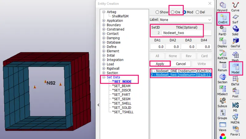
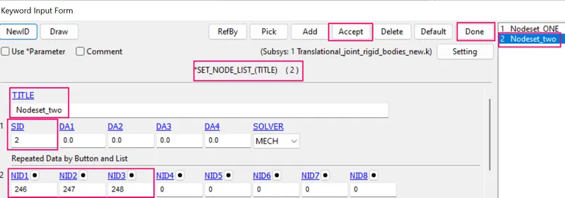
STEP 7E3 : To Associate the extra nodes to respective parts by *CONSTRAINED_EXTRA_NODES_SET
- These newly created nodes are in the space and do not belong to any of the parts now. So, for associating these nodes with part 1 and part 2, *CONSTRAINED_EXTRA_NODES_SET is used.
- Nodes 243, 244 and 245 are constrained to part 1 and nodes 246, 247 and 248 to part 2 using *CONSTRAINED_EXTRA_NODES card.
- Sidebar > keyword manager > model > all > constrained > CONSTRAINED_EXTRA_NODES_SET > set pid -1> assigned NSID -1 outter box shell part > accept and done.
- Sidebar > keyword manager > model > all > constrained > CONSTRAINED_EXTRA_NODES_SET > set pid-2 > assigned NSID -2 inner box shell part > accept and done.
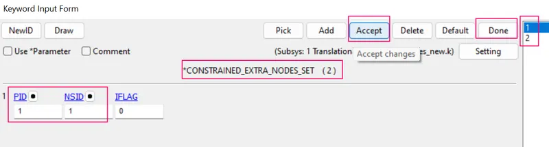
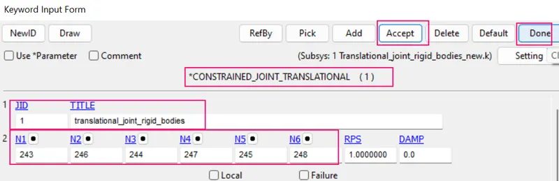
STEP 7E4 : Creation of *CONSTRAINED_JOINT_TRANSLATIONAL card .
- Now, the translational joint is defined by using *CONSTRAINED_JOINT_TRANSLATIONAL keyword. six nodes should be defined to create a translational joint.
- N1, N3 and N5 of part 1 and nodes N2, N4 and N6 of part 2
- Sidebar > keyword manager > model > all > constrained > CONSTRAINED_JOINT_REVOLUTE > JID-1 > Title is Revolute_joint > assigned the node ids N1=243, N2=246, N3=244, and N4=247,N5=245, N6=248 > accept and done.
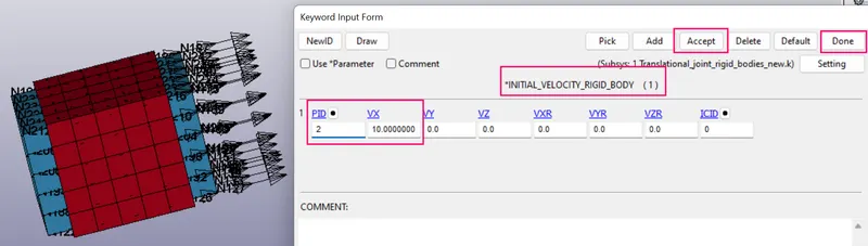
STEP 7F: Define the initial velocity to the inner box shell.
- Initial Velocity is assigned to the Inner box By INITIAL_VELOCITY_RIGID_BODY, with rotational velocities in the X, Y, Z axis.
- In order to define the initial velocity by the following steps.
- Sidebar > model > keywordmanager > all > INITIAL > VELOCITY_RIGID_BODY > assigned PID-2 (for inner box) > initial translational velocity in x-directionis 10 mm/ms > accept and done.
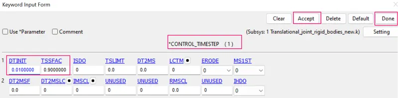
STEP 7G : Define a control time step card.
- In order to create control timestep card by the following steps.
- Sidebar > keywordmanager > all > control > timestep >TSSFAC-0.9 > DT-initial-0.01 ms > accept and done.
STEP 7H : Define a control termination card.
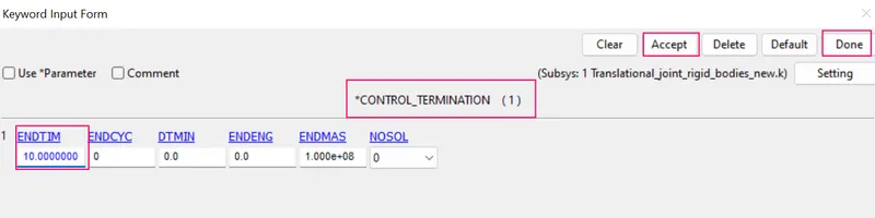
1. The main purpose of control termination card is to stop the job.
2. In order to assign the control termination card by the following steps.
3. Side bar > model and part > keyword manager > control > termination > specify termination time is 5 ms > accept and done.
STEP 7I : Define the output database as Binary D3 plot.
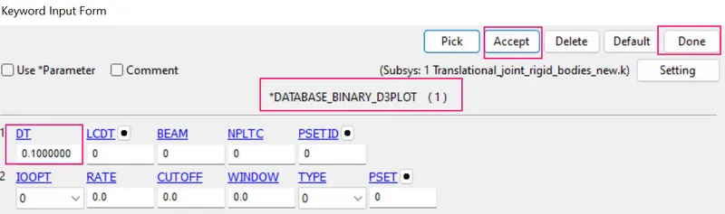
- DATABASE_BINARY_D3PLOT ensures d3 plot files which its stores stress strain contour of the entire deformed model.
- In order to create the DATABASE_BINARY_D3PLOT by the fllowing steps.
- Side bar > model and part > keyword manager > database > select DATABASE_BINARY_D3PLOT > DT value is 0.1 ms is a time interval between output states > accept & done.
STEP 7J: Model checkup
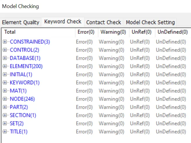
- The model is checked for any errors before solving using model checker.
- After all the errors are cleared,and is ready to run in LS DYNA manager for solving the scenario.
- Warnings we can ignore ,once model check is run , it will look like as shown in picture below
STEP 7K : Run the Simulation of translational joint between rigid bodies
- To run the using LS-run by the following steps.
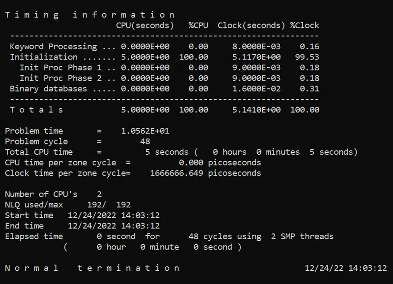
- Title bar > file > run LS-dyna > runned the k file of translational_joint_rigid_bodies > achieved normal temination. it means the model is ready for post processing.
- During simulation run window will popup as shown in picture below,
STEP 7L : POST PROCESSING
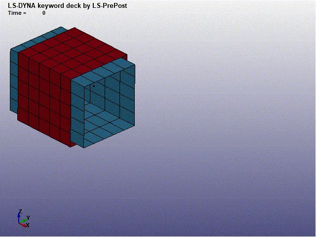
- In order to see simulation results , we have to open output file in LS-Prepost by the following steps.
- In LS-prepost -Title bar > file > open > LS -Dyna binary plot > selected the d3 plot file > visibled to see animation file.
CASE 8 : Creation of translational joint between deform bodies.
- Same box shell FE model used in the previous case:7
STEP 8A : Creation of material card for outter and inner shell box
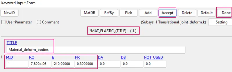
1. To create the material card for 2 box shell bodies by the following steps.
2. I had prefereed to choose material type is MAT_ELASTC_001
3. This is Material Type 1. This is an isotropic hypoelastic material and is available for beam, shell, and solid elements in LS-DYNA
4. Side bar > model and part > keyword manager > MAT > all > MAT_ELASTC_001
5. Created new ID is 1 and give title is Material_rigid_bodies and specified the properties value as Kg-mm-ms unit system.
Where,
- RO- density of a steel = 7.8 * 10⁻⁶ Kg /mm³.
- E-Youngs modulus = 210 kg / mm ms²
- PR-Poissons ratio= 0.30.
STEP 8B : Creation of section card for for outter and inner box shell
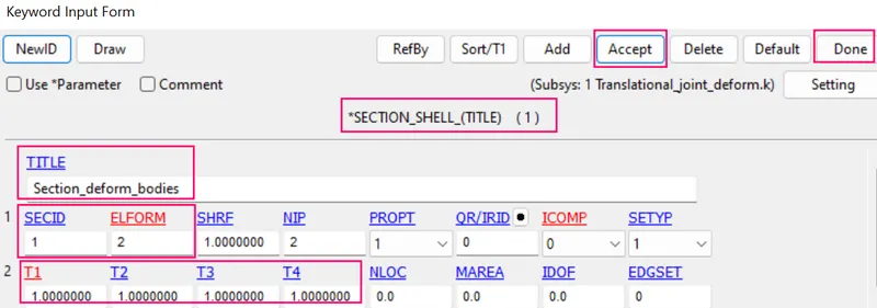
1. In this section element formulation ,integration rule ,nodal thickness and cross sectional properties are defined.
2. Side bar > model and part > keyword manager >all > section >specified the thickness value is 1.0 mm > accept and done.
STEP 8C : Assign the material card and section card to the rigid bodies part.
1. Inorder to create the rigid bodies cylindrical shell part by the following steps.
2. Side bar > model and part > keyword manager >model > part > assigned the MID and SECID cards to rigid bodies part >accept and done.
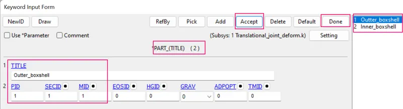
STEP 8D : Creation of cylindrical joint between two deformable bodies using *CONSTRAINED_NODAL_RIGID_BODY(CNRB).
STEP 8D1 : To Associate extra nodes to respective parts by *CONSTRAINED NODAL RIGID BODY (CNRB)
- Create Entity > Constrained > Nodal Rigid Body(CNRB) > Create.
- Toggle off the CrePNode option which will disable the creation of PNODE at the mass center of selected nodes.
- Now specify the PND is 243 node as the first point followed by inner box outter circumference nodes selected by path and hit apply option.
- A CNRB(3)will be created with PNODE at the 243 node position.
- similarly, Create Entity > Constrained > Nodal Rigid Body(CNRB) >specify the PND is 244 node followed by outter box outter circumference nodes selected by path and hit apply option > created CNRB(4)will be created with PNODE at the 244 node position.
- Create Entity > Constrained > Nodal Rigid Body(CNRB) >specify the PND is 245 node followed Outter box outter circumference nodes selected by path and hit apply option > created CNRB(5)will be created with PNODE at the 245 node position.
- Create Entity > Constrained > Nodal Rigid Body(CNRB) >specify the PND is 246 node followed by inner box outter circumference nodes selected by path and hit apply option > created CNRB(6)will be created with PNODE at the 246 node position.
- Create Entity > Constrained > Nodal Rigid Body(CNRB) >specify the PND is 247 node followed by inner box outter circumference nodes selected by path and hit apply option > created CNRB(7)will be created with PNODE at the 246 node position.
- Create Entity > Constrained > Nodal Rigid Body(CNRB) >specify the PND is 248 node followed by inner box outter circumference nodes selected by path and hit apply option > created CNRB(8)will be created with PNODE at the 246 node position.
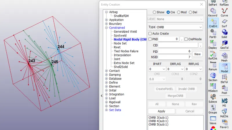
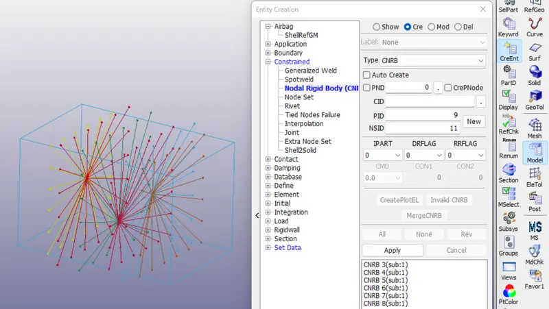
- Checked the constrained nodal rigid body in keywordmanager.
- Sidebar> model > keywordmanager > constrained > Nodal rigid body > assigned NSID-503 > accept and done.
- Similary checked other NSIDs.
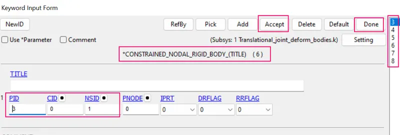
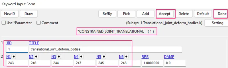
STEP 8D2 : Creation of *CONSTRAINED_JOINT_TRANSLATIONAL card .
- Now, the translational joint is defined by using *CONSTRAINED_JOINT_TRANSLATIONAL keyword. six nodes should be defined to create a translational joint.
- N1, N3 and N5 of part 1 and nodes N2, N4 and N6 of part 2
- Sidebar > keyword manager > model > all > constrained > CONSTRAINED_JOINT_TRANSLATIONAL > JID-1 > Title is Translational_joint_deform_bodies > assigned the node ids N1=243, N2=246, N3=244, and N4=247,N5=245, N6=248 > accept and done.
STEP 8E : Define the initial velocity to the inner box.
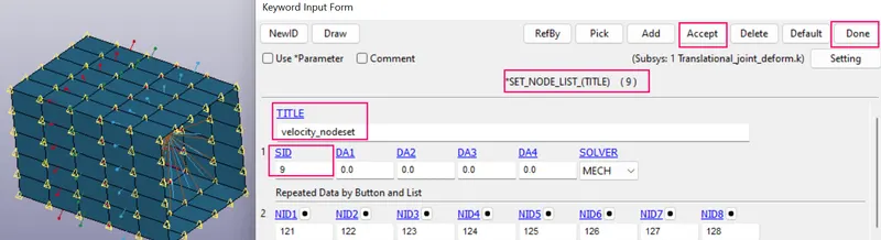
STEP 8E1 : Creation of Nodeset for the inner box.
- Before define the initial velocity we have to create the Nodeset for inner box.
- In order to create the NODESET by the following steps.
- Sidebar > model > create entity > SETDATA > SETNODE > SETID-9 > selected the nodes of the inner box by part > apply > done.
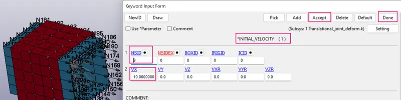
STEP 8E2 : Define the initial velocity to the inner box.
- Initial Velocity is assigned to the Inner cylinder By INITIAL_VELOCITY with rotational velocities in the X, Y, Z axis.
- In order to define the initial velocity by the following steps.
- Sidebar > model > keywordmanager > all > INITIAL > VELOCITY > assigned NSID-9 (for inner box) > initial translational velocity in x-directionis 10 mm/ms > accept and done.
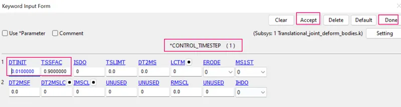
STEP 8F1 : Define a control time step card.
- In order to create control timestep card by the following steps.
- Sidebar > keywordmanager > all > control > timestep >TSSFAC-0.9 > DT-initial-0.01 ms > accept and done.
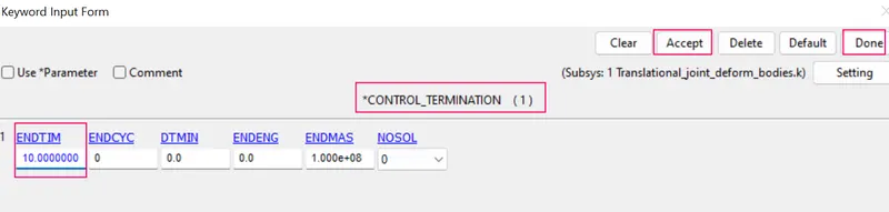
STEP 8F2 : Define a control termination card.
1. The main purpose of control termination card is to stop the job.
2. In order to assign the control termination card by the following steps.
3. Side bar > model and part > keyword manager > control > termination > specify termination time is 5 ms > accept and done.
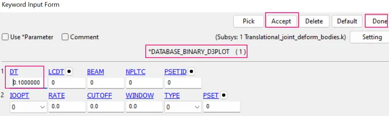
STEP 8G : Define the output database as Binary D3 plot.
- DATABASE_BINARY_D3PLOT ensures d3 plot files which its stores stress strain contour of the entire deformed model.
- In order to create the DATABASE_BINARY_D3PLOT by the fllowing steps.
- Side bar > model and part > keyword manager > database > select DATABASE_BINARY_D3PLOT > DT value is 0.1 ms is a time interval between output states > accept & done.
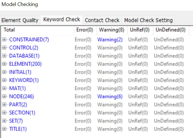
STEP 8H: Model checkup
- The model is checked for any errors before solving using model checker.
- After all the errors are cleared,and is ready to run in LS DYNA manager for solving the scenario.
- Warnings we can ignore ,once model check is run , it will look like as shown in picture below
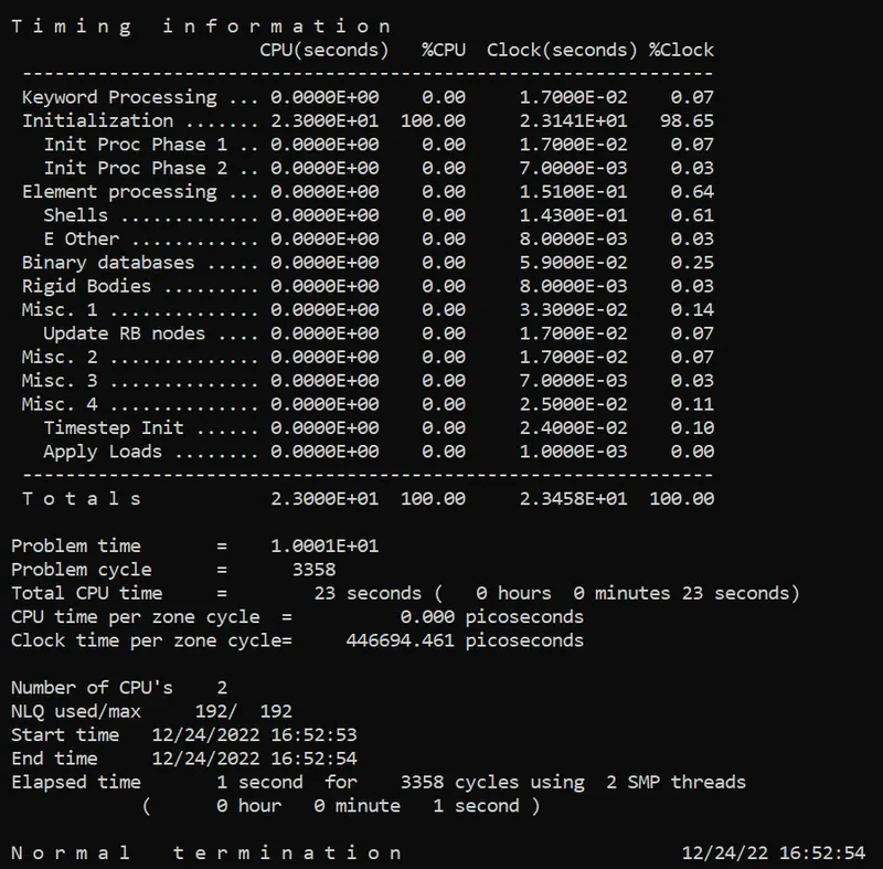
STEP 8I : Run the Simulation of cylindrical joint between rigid bodies
- To run the using LS-run by the following steps.
- Title bar > file > run LS-dyna > runned the k file of Translational_joint_deform_bodies > achieved normal temination. it means the model is ready for post processing.
- During simulation run window will popup as shown in picture below,
STEP 8J : POST PROCESSING
- In order to see simulation results , we have to open output file in LS-Prepost by the following steps.
- In LS-prepost -Title bar > file > open > LS -Dyna binary plot > selected the d3 plot file > visibled to see animation file.
COMPARISON OF SIMULATION OF VARIOUS JOINTS.
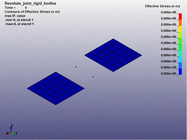
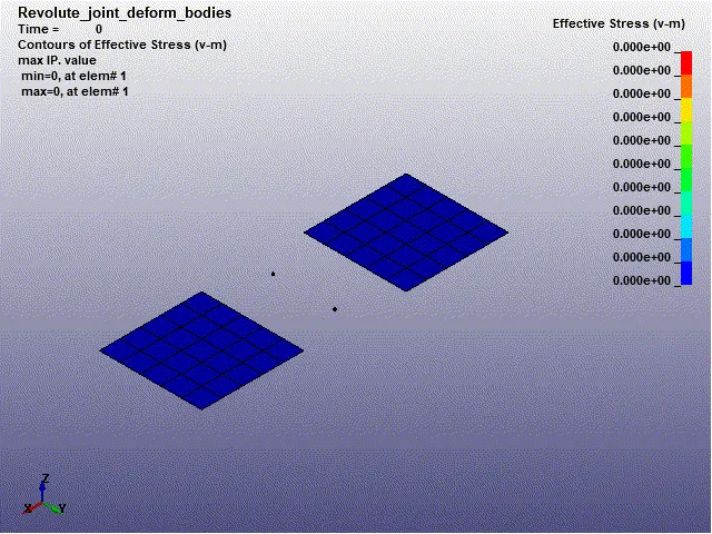
1. simulations of revolute joint between rigid bodies and deformable bodies.
revolute joint between rigid bodies
revolute joint between deformable bodies
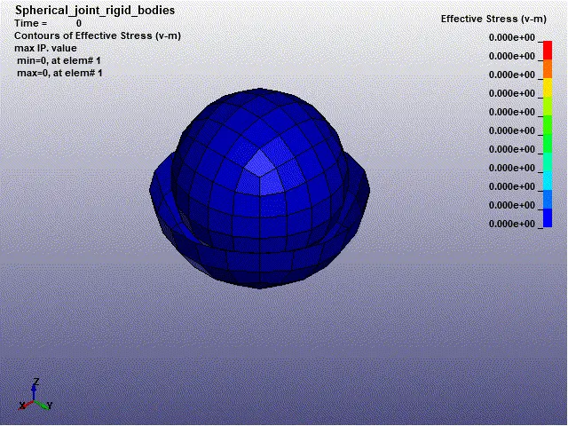
2. simulations of spherical joint between rigid bodies and deformable bodies.
Spherical joint between rigid bodies
Spherical joint between deformable bodies
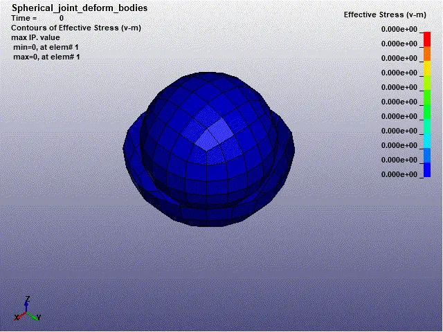
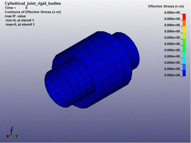
3. simulations of cylindrical joint between rigid bodies and deformable bodies.
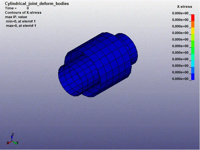
Cylindrical joint between rigid bodies
Cylindrical joint between deformable bodies
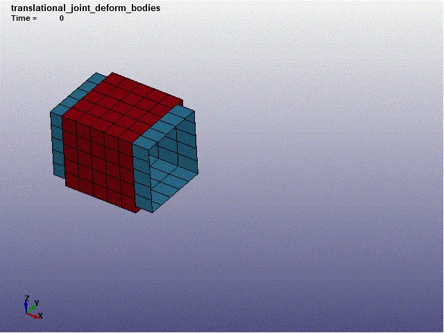
4. Simulations of translational joint between rigid bodies and deformable bodies.
Translational joint between rigid bodies
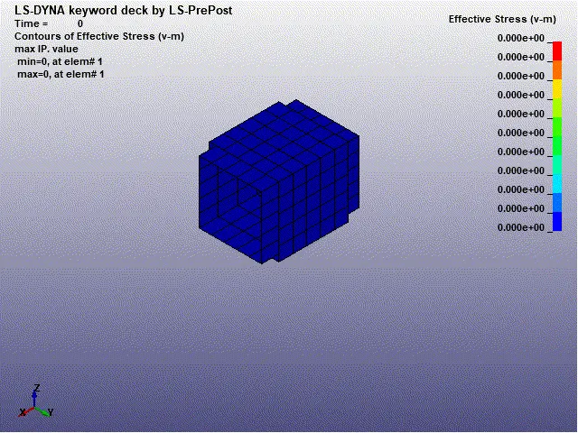
Translational joint between deformable bodies
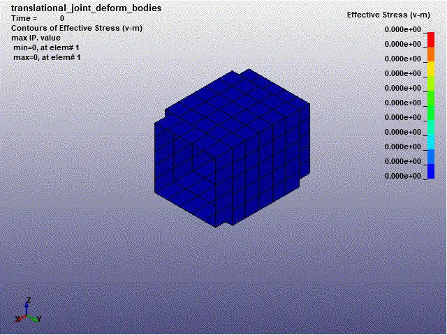
CONCLUSION:
- The keyword files necessary to demonstrate spherical, revolute, cylindrical, and translational joints between two rigid bodies using the *CONSTRAINED_EXTRA_NODES card in LS Pre-Post.
- Also, the keyword files necessary to demonstrate spherical, revolute, cylindrical, and translational joints between two deformable bodies are created in LS Pre-Post using the *CONSTRAINED_NODAL_RIGID_BODY card.
- Finally, we have simulated all joints for two rigid bodies and two deformable bodies using the LS-Run. We also obtained the animations for all the joints for both rigid bodies and deformable bodies.