Assignment 4-RADIOSS Material Laws Challenge
RADIOSS MATERIAL LAWS CHALLENGE
Aim:
- To run the simualtion for the plate and rigid ball by using Jhonson Cook Material, Elastic material,Elastic plastic piecewise linear material and Elasto Plastic Material with Brittle Failure as per the cases given in the question by using Radioss solver.
Objective:
- Run the simulation for all the 7 cases as given in the statement.
- Run the simulation by changing the material ,shell properties and failure parameters.
- Tabulate the total number of cycles, Energy Error,Mass Error and Simulation Time.
- Plot the graphs for all the 7 cases.
- Compare all the 7 cases results.
Data base :
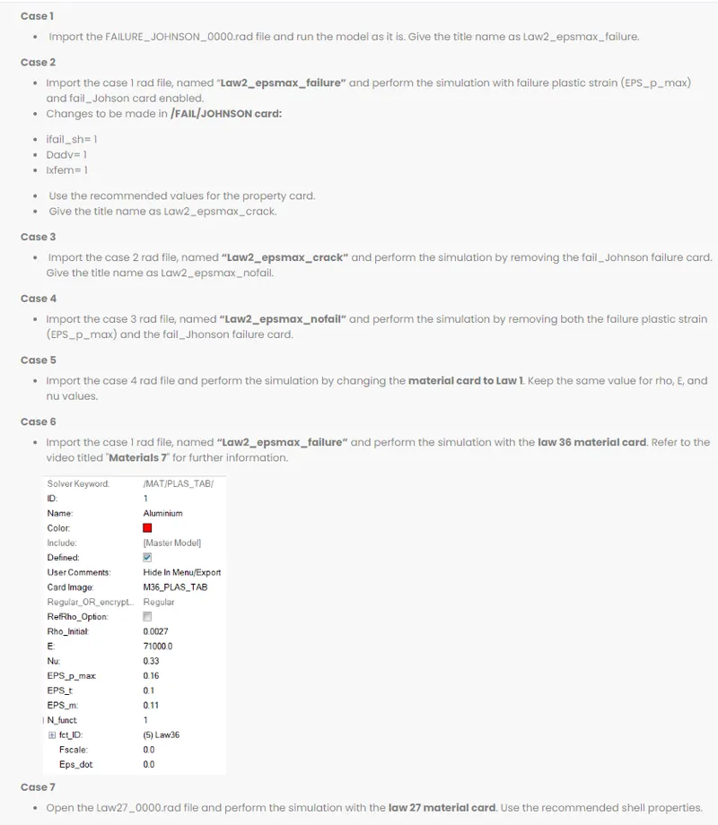
Radioss files :

Software used :
- Explicit solver - Radioss
Procedural steps :
Case 1 : Run the model as it is with default failure parameters.
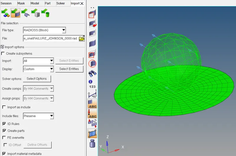
STEP1: Import the FAILURE_JOHNSON_0000.rad file and run the model as it is . Title name law2_epsmax_failure.
- Inorder to import the .rad file by the following steps.
- File > import > solverdeck > file type- radioss block > file name as FAILURE_JOHNSON_0000.rad > imported it.
STEP 2 : Check default material parameters
- Model tree > material > aluminium
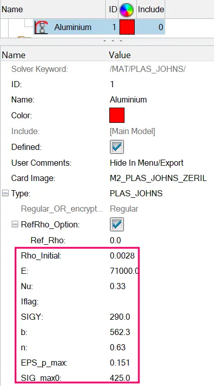
Aluminium material properties
Initial Density(ρi) = 0.0028 gm /mm³.
Youngs modulus(E) = 71000 Mpa.
Poissons ratio (ν) = 0.33.
Yield stress (σy ) = 290 Mpa.
Plastic hardening parameter (b) = 562 Mpa.
Plastic hardening exponent (n) = 0.63
Failure plastic strain (EPS_p_max) = 0.151
Maximum stress (SIG_Max0) = 425
STEP 3 : RADIOSS Job
- Run solver.
- To do that,Go to Analysis panel in Panel Area > Radioss > Select the Input File > Radioss.

- Options helps to choose number of cores to solve this problem, here we have chosen 4 number of cores by (-nt 4).
- Then click on Radioss, and new window will get pop-up. A simulation will start to show result.
- After selecting the input file and completing the set up to run the solver.
- Radioss will pop the solver view stating Radioss Job Completed.
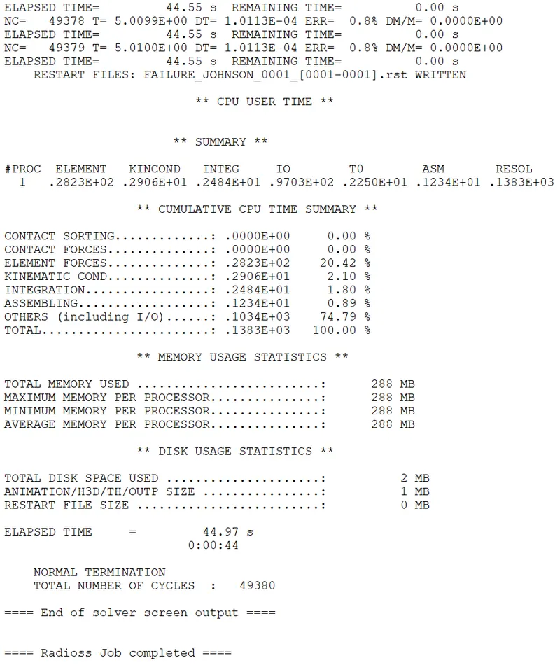
STEP 4 : Check engine [00001.rad] file
- After the end of the solver output,Go and check the whether the engine has been edited or not.
- To check,Go to file location where you have saved the starter file.
- Open the FAILURE_JOHNSON_0001.rad file with notepad.
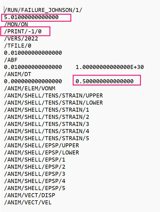
STEP 5 : Check animation files
- We have eneterd the T frequency value to create 10 animation files,but 11 animation files have been created which is shown in below,
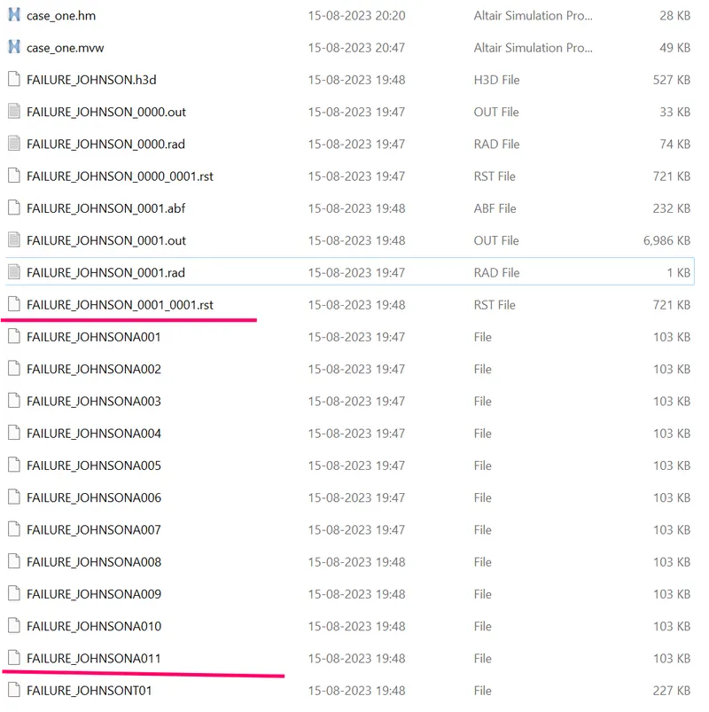
STEP 6 : Check errors.
- Now Engine Output File [00001.out] has been generated after analysis.
- The Engine Output File [00001.out] contains the data like
- Time Step.
- Energy Error.
- Mass Error.
- Internal Energy Error.
- Kinetic Energy Error.
- Contact Energy Error.
- Here check for the Mass Error and Energy Error.
- The obtained values for Energy Error,Mass Error,Internal Energy Error,Kinetic Energy Error and Contact Energy Error has been shown in below
- The Acceptable Energy Error Range is -15% to +5%.
- The Acceptable Mass Error Range is 0 to 2%.
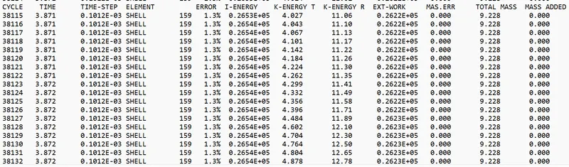
Maximum energy error = 1.3%
Maximum kinetic energy = 179.25 gm (mm /ms)²
Maximum internal energy = 0.2731E+05
Max mass error = 0 .
STEP 10 : Post processing
1) Review the Simulation using -HyperView.
2) Plot the graphs using -Hypergraph 2D.
1) Review the Simulation using -HyperView.
- First to begin the postprocessing in the Hypermesh,Split the Screen .
- Import the animation file .h3d into the hyperview.
- After importing the .h3d file into the GUI,Enable the contour.
- The contour tool create contour plots of a model graphically visualize the analysis results.
- To enable contour,Go to Results > ToolBar > Contour .
- Now switch to the Von Misses Stress in result type and select the component,select the averaging method as simple and then click apply.
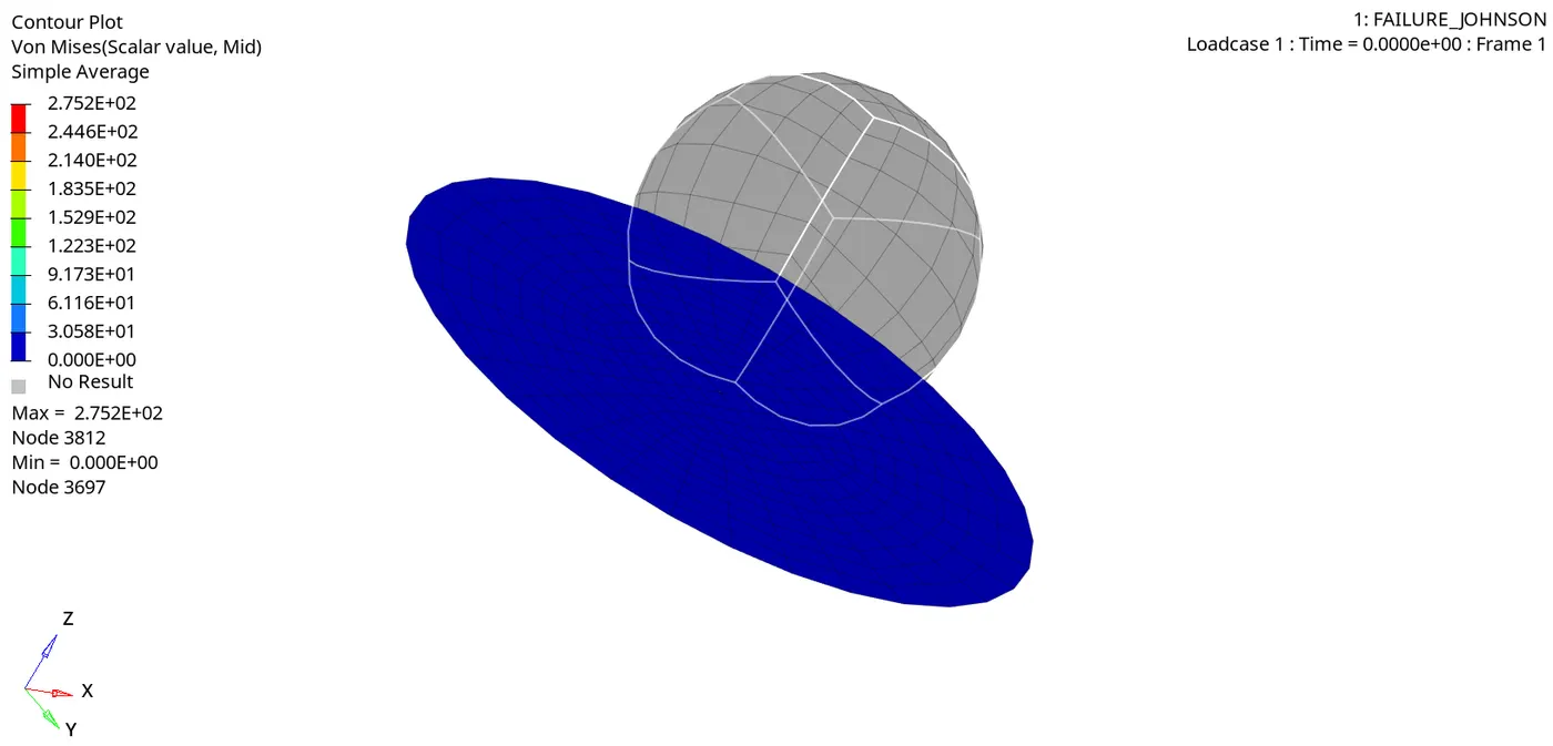
Max stress developed = 2.75E+02 Mpa.
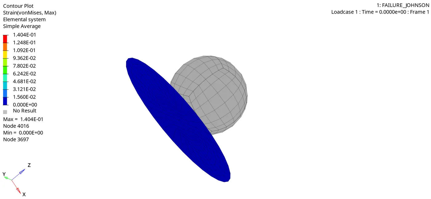
Max strain = 0.140
2) Plot the graphs using -Hypergraph 2D.
- Now plot the graphs using Hypergraph 2D,We are plotting the graphs to see what is happening in the rail component.
- Hypergraph 2D is a powerful data analysis and plotting tool with interfaces to many popular file formats.
- Here switch to the Hypergraph 2D to plot the graphs.
- To switch,Go to Client Selector > Choose the Hypergraph 2D.
2a) Plot of the Rigid Wall Forces.
- To plot the graph,go to Hypergraph 2D > Data File > Solver_file_T01 > Apply.
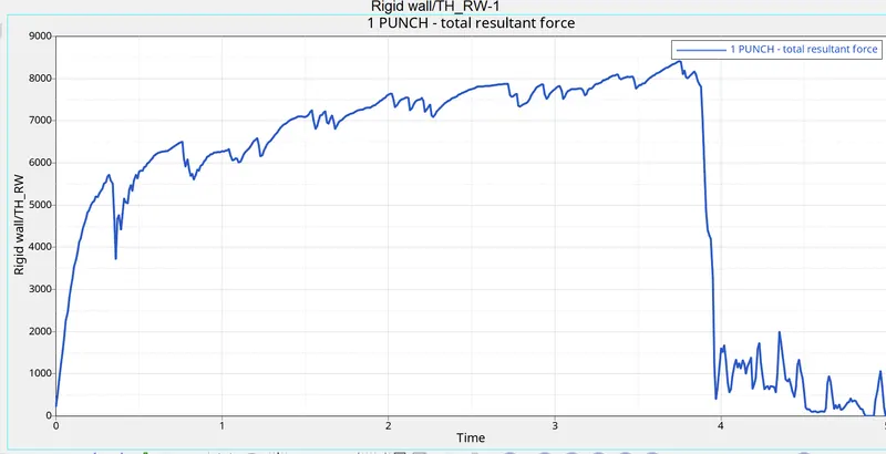
Max punch resultant force = 8408.6 N
- Initially there is no contact between rigidball and the aluminium plate , so the curve is in origin.
- When the rigidball hits the plate the curve starts to increasing and suddenly decreasing, because after reaching the ultimate stress,the elements gets deleted and there will be no contact after the elements gets deleted.
A. Kinetic Energy :
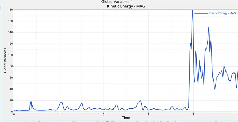
- Max kinetic energy = 179.25 gm (mm /ms)²
- Here the initial velocity is zero,So the curve starts from origin.
- After kinetic energy increasing because,rigid ball is hitting the plate and again its slightly decreasing due to element breakage,After the elements deleted,there will be no contact,So its decreasing.
B. Internal energy :
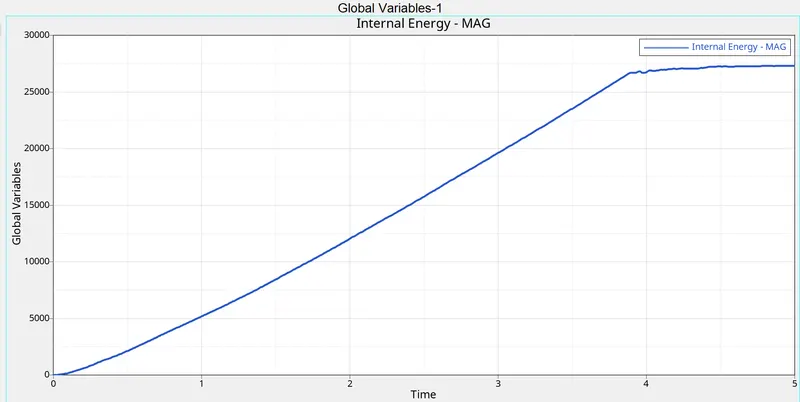
- Max internal energy = 27322 gm (mm /ms²)
- Initially internal energy of the aluminium is zero, because there is no contact between rigidball and plate. after rigidball hitting the plate deformation occurs , then the internal energy of the plate gradually increases,why because the deformation or displacement is happening,when the displacement increases the internal energy increases.
C. Contact energy :
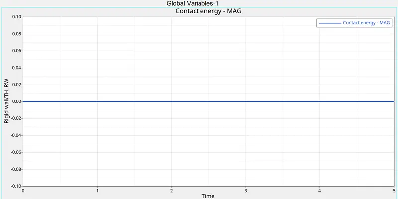
- Contact energy is zero, and also constant.Because rigidball get in contact with the deformable bodies ( plate ) .
- If deformable bodies (plate) get in contact with the rigidball then the contact energy increasing.
D. hourglass energy :
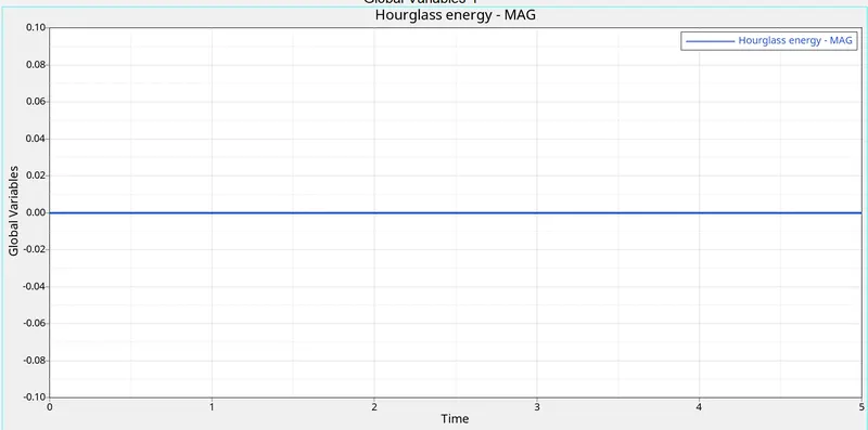
- The hourglass energy is constant and also zero.,because the balance not happpened in the rest of energie that's the reason why hourglass energy is constant.
E. Total energy
- Max total energy = 27375 gm (mm /ms²).
- Total Energy is sum of Kinetic Energy+Contact Energy+Hourglass Energy + Internal Energy.
- Total Energy is the combination of all energies.
- So its goes on increasing,Internal energy curve is similar to the total energy.
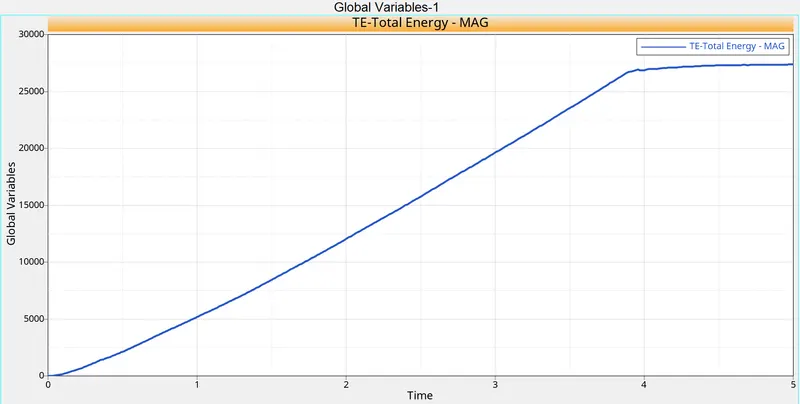
- Why Total energy is decreasing, Let's see mathematically
- Energy Error=1.3%
- = (1.3 / 100) x max.total energy
= (1.3 / 100) x 27375
= 355.875 gm (mm /ms)²
- Now Subract this value from Maximum Total Energy.
= 27375 - 355.875
= 27019 gm (mm² /ms²) same we got minimum total energy grom the above plot.
Case 2 : Change the Values in Jhonson Failure Card
- For this case we have to import the required file i.e. FAILURE_JOHNSON_0000.
- In this case we have to edit some parameters, such as Ifail_sh=1, Dadv=1, and Ixfem=1.
- Ifail_sh stands for Shell failure flag, which enable Shell is deleted or cracked for one integration point or layer.
- Dadv is the Criterion for the crack advancement (Only active if with Ixfem =1)
- And Ixfem is failure type, in which element is either deleted or cracked.
- Once required parameters are assigned, then we will save our model with name i.e. Law2_epsmax_failure. And failure card will look like as shown in picture below.
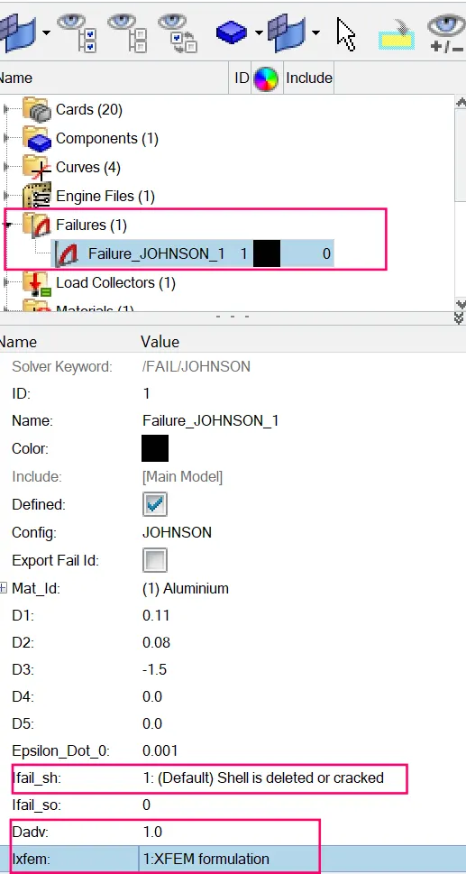
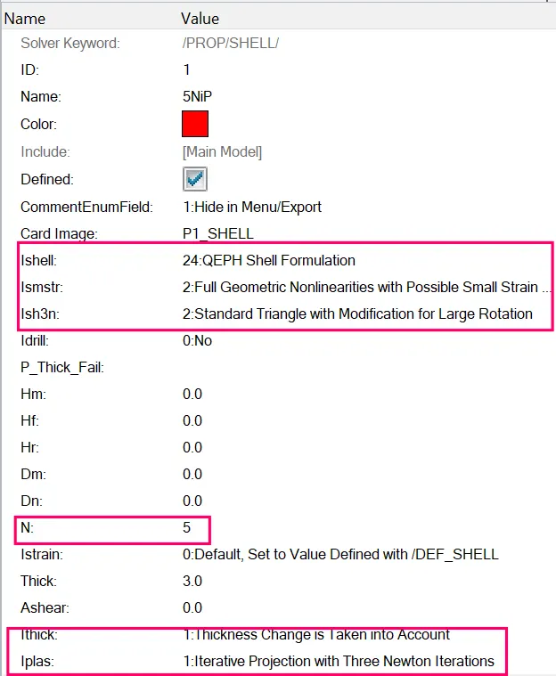
- Property card values
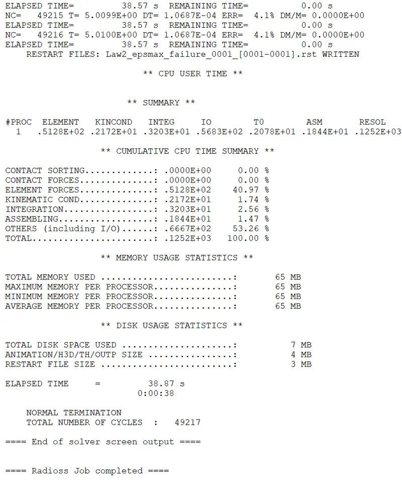
STEP 3 : RADIOSS Job
- Run solver.
- To do that,Go to Analysis panel in Panel Area > Radioss > Select the Input File > Radioss.

- Options helps to choose number of cores to solve this problem, here we have chosen 4 number of cores by (-nt 4).
- Then click on Radioss, and new window will get pop-up. A simulation will start to show result.
- After selecting the input file and completing the set up to run the solver.
- Radioss will pop the solver view stating Radioss Job Completed.
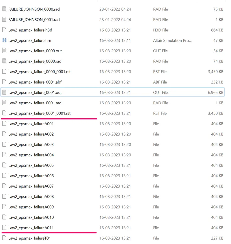
STEP 4 : Check animation files
- We have eneterd the T frequency value to create 10 animation files,but 11 animation files have been created which is shown in below,
STEP 5 : Check errors.
- Now Engine Output File [00001.out] has been generated after analysis.
- The Engine Output File [00001.out] contains the data like
- Time Step.
- Energy Error.
- Mass Error.
- Internal Energy Error.
- Kinetic Energy Error.
- Contact Energy Error.
- Here check for the Mass Error and Energy Error.
- The obtained values for Energy Error,Mass Error,Internal Energy Error,Kinetic Energy Error and Contact Energy Error has been shown in below
- The Acceptable Energy Error Range is -15% to +5%.
- The Acceptable Mass Error Range is 0 to 2%.
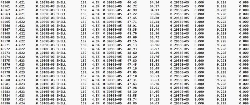
Maximum energy error = 4.5 %
Maximum kinetic energy = 210.28 gm (mm /ms)²
Maximum internal energy = 30812.47 gm (mm /ms²)
Max mass error = 0 .
STEP 10 : Post processing
1) Review the Simulation using -HyperView.
2) Plot the graphs using -Hypergraph 2D.
1) Review the Simulation using -HyperView.
- First to begin the postprocessing in the Hypermesh,Split the Screen .
- Import the animation file .h3d into the hyperview.
- After importing the .h3d file into the GUI,Enable the contour.
- The contour tool create contour plots of a model graphically visualize the analysis results.
- To enable contour,Go to Results > ToolBar > Contour .
- Now switch to the Von Misses Stress in result type and select the component,select the averaging method as simple and then click apply
Stress contour results
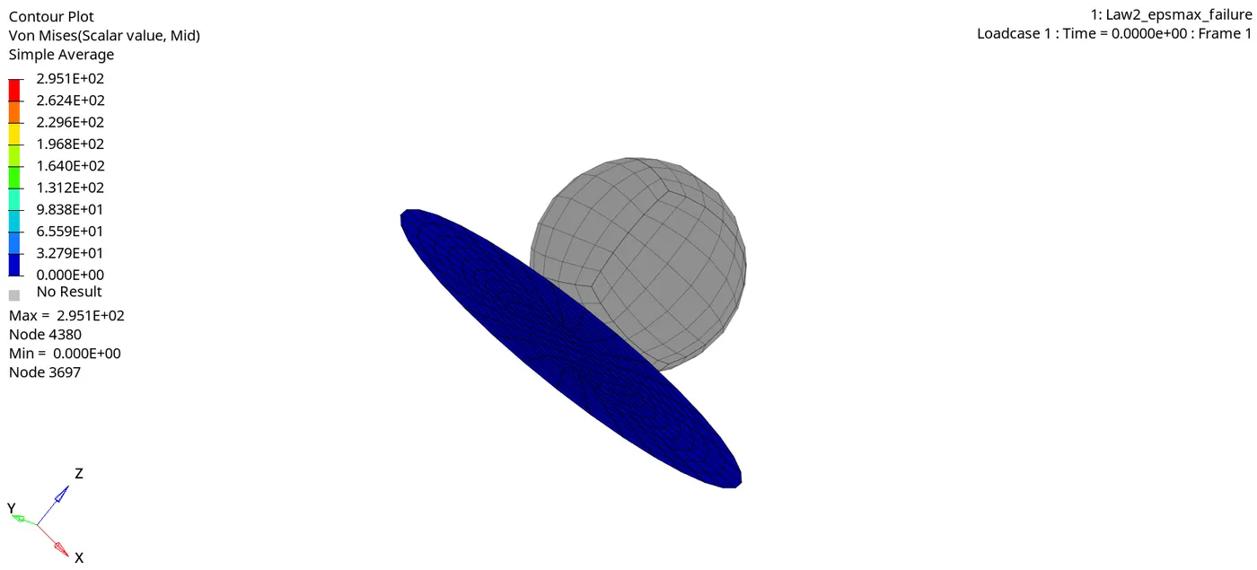
Max stress developed = 295 Mpa
Strain contour results
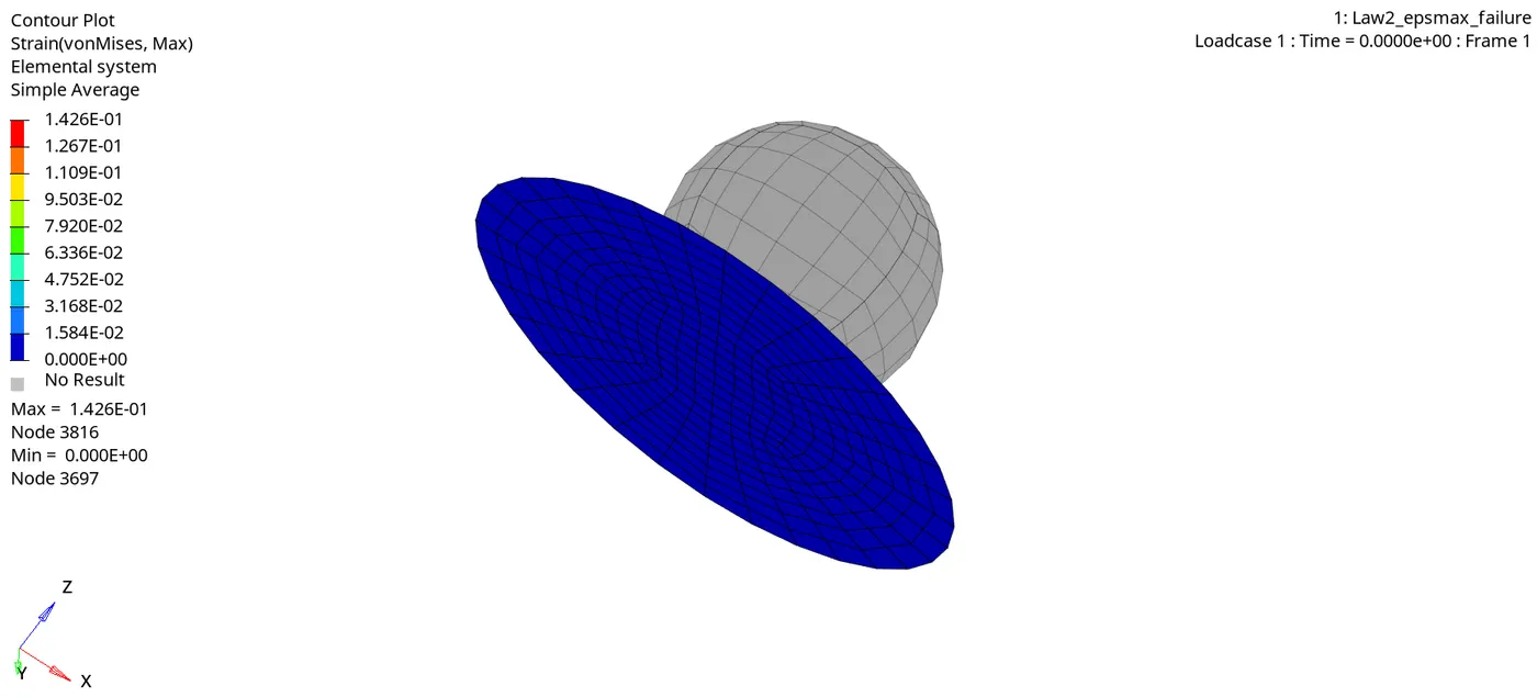
Max strain = 0.147
- Here the set the maximum Eps_Max value =0.151,The elements should be deleted after reaching the Eps_Max=0.151.
- But here the maximum strain shown here is 1.426E-01 which is 0.147.Because the solver won't record when the elements get deleted,So this is the reason.
- The elements will be failing and getting deleted,when the rigid ball goes on hitting the aluminium plate.
2a) Plot of the Rigid Wall Forces.
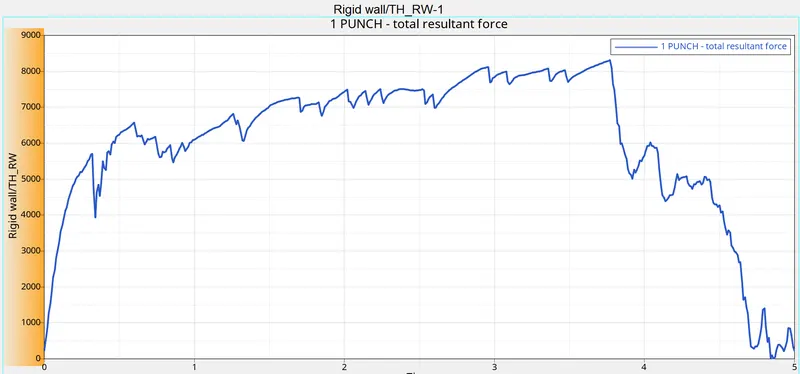
- Max punch resultant force = 8310 N
- Initially there is no contact between rigidball and the aluminium plate , so the curve is in origin.
- When the rigidball hits the plate the curve starts to increasing and suddenly decreasing, because after reaching the ultimate stress,the elements gets cracked and deleted and there will be no contact after the elements gets deleted.
A. Kinetic Energy :
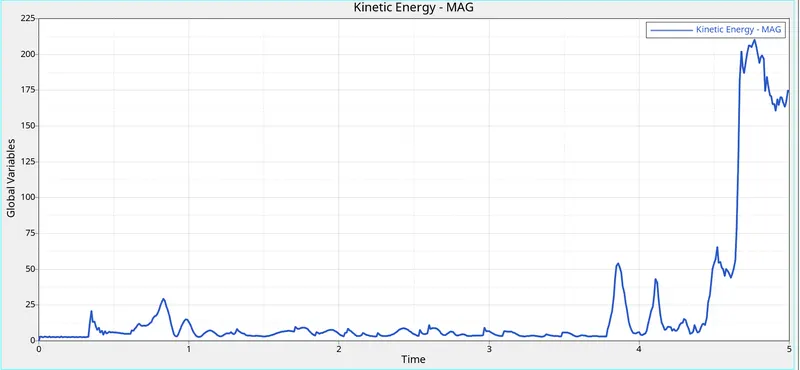
- Max kinetic energy = 210.28 gm (mm /ms)²
- The kinetic energy starts from origin and goes on increasing due to deformation of elements,Its increasing after 4ms because the deformation of elements are controlled by johnson cook material parametrs.And its suddenly decreasing because the elements getting deleted after crack and there will be no contact,so its slightly decreasing.
B. Internal energy :
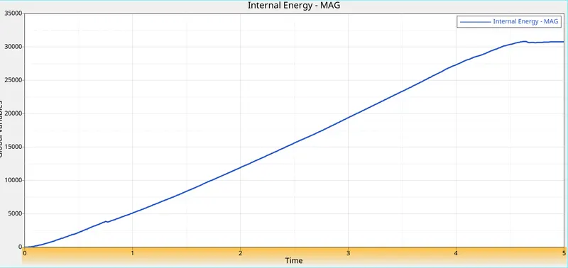
- Max internal energy = 30812.47 gm (mm /ms²)
- Initially internal energy of the aluminium plate is zero, because there is no contact between rigidball and plate. after rigidball hitting the plate deformation occurs , then the internal energy of the plate gradually increases,why because the deformation or displacement is happening,when the displacement increases the internal energy increases.
C. Contact energy :
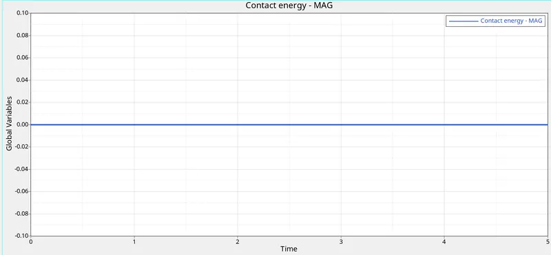
- Contact energy is zero, and also constant.Because rigidball get in contact with the deformable bodies ( plate ) .
- If deformable bodies (plate) get in contact with the rigidball then the contact energy increasing.
D. hourglass energy :
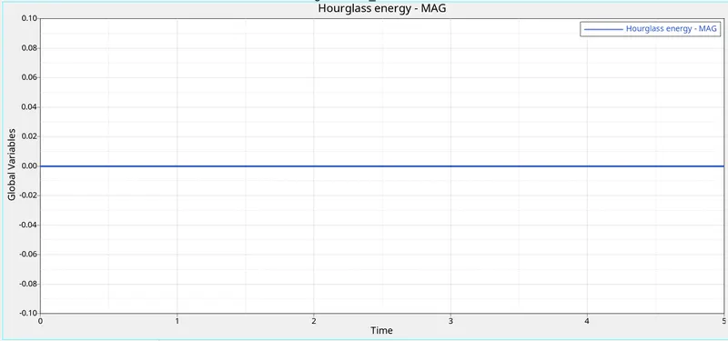
- The hourglass energy is constant and also zero.,because the balance not happpened in the rest of energie that's the reason why hourglass energy is constant.
E. Total energy
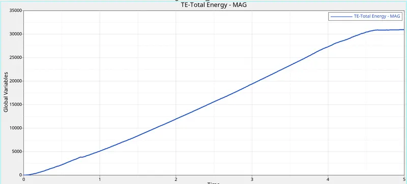
- Max total energy = 30953 gm (mm /ms²).
- Total Energy is sum of Kinetic Energy+Contact Energy+Hourglass Energy + Internal Energy.
- Total Energy is the combination of all energies.
- So its goes on increasing,Internal energy curve is similar to the total energy.
CASE 3 : Delete the failure johnson card.
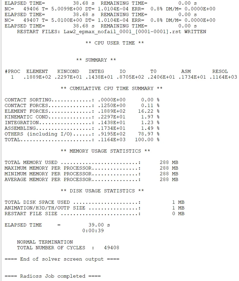
- Import the case 2 rad file, named “Law2_epsmax_crack” and perform the simulation by deleting the the fail_Johnson failure card. Give the title name as Law2_epsmax_nofail.
STEP 1 : RADIOSS Job
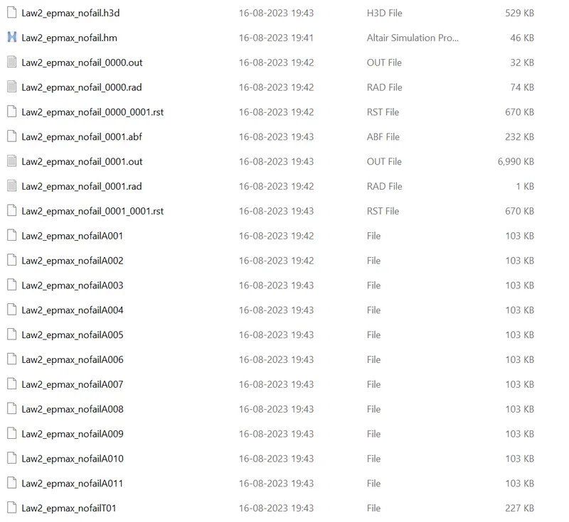
STEP 2 : Check animation files
STEP 5 : Check errors.
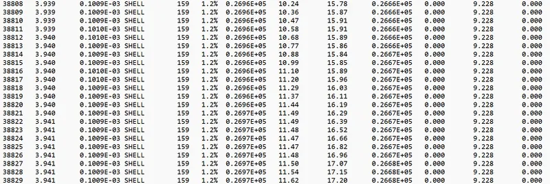
Maximum energy error = 1.2 %
Maximum kinetic energy = 332 gm (mm /ms)²
Maximum internal energy = 27443 gm (mm /ms²)
Max mass error = 0
STEP 10 : Post processing
1) Review the Simulation using -HyperView.
Stress contour results
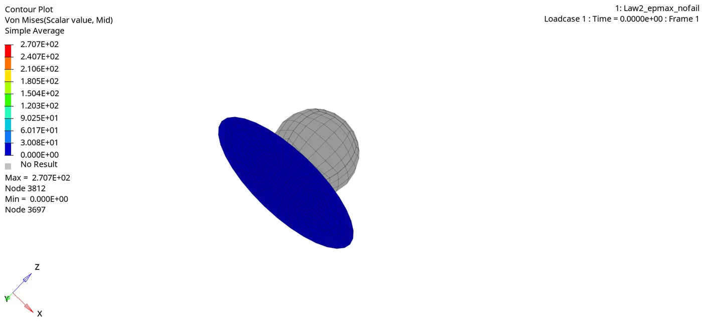
Max stress developed = 270 Mpa
Strain contour results
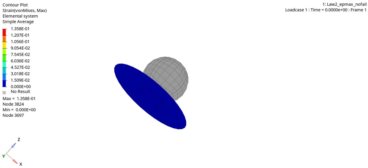
- Here the maximum Eps_Max value =0.151,The elements should be deleted after reaching the Eps_Max=0.151.
- But here the maximum strain shown here is 1.358E-01 which is 0.135.Because the solver won't record when the elements get deleted,So this is the reason.
- The elements will be failing and getting deleted,when the rigid ball goes on hitting the aluminium plate.
2a) Plot of the Rigid Wall Forces.
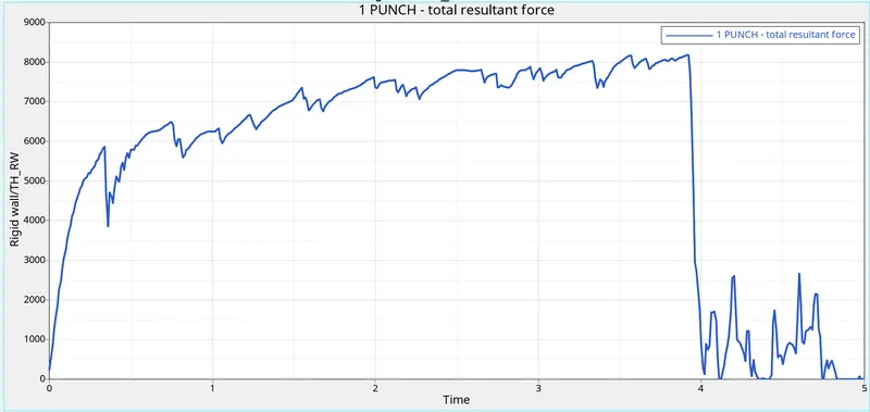
- Max punch resultant force = 8174 N.
A. Kinetic Energy
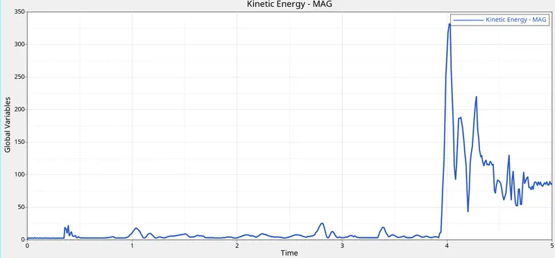
- Max kinetic energy = 332 gm (mm /ms)²
B. Internal energy
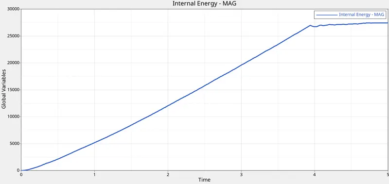
- Max internal energy = 27443 gm (mm /ms²)
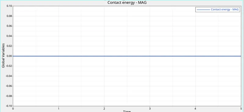
C. Contact energy
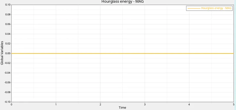
D. hourglass energy
E. Total energy
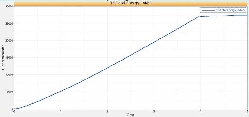
Max total energy = 27528 gm (mm /ms²)
Case 4 - Delete the EPS_P_Max Value from the Material Card :
- Import the case 3 rad file, named “Law2_epsmax_nofail” and perform the simulation by removing both the failure plastic strain (EPS_p_max) and the fail_Jhonson failure card.
STEP 1 : RADIOSS Job
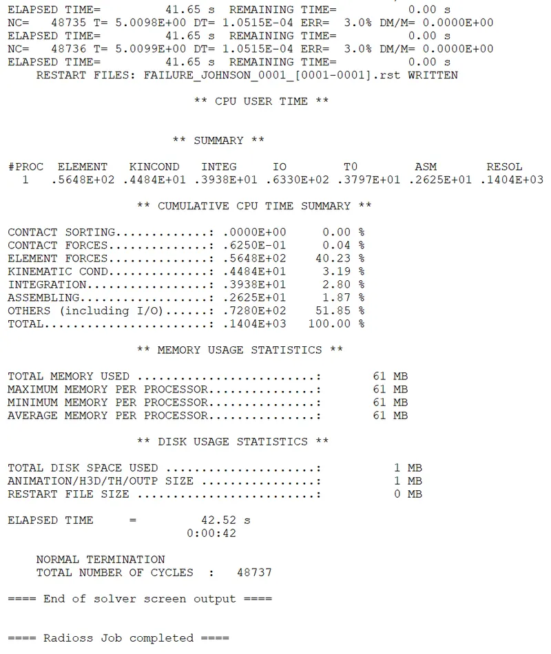
STEP 2 : Check errors.

Maximum energy error = 3.0 %
Maximum kinetic energy = 3.77 gm (mm /ms)²
Maximum internal energy = 64665 gm (mm /ms²)
Max mass error = 0
STEP 10 : Post processing
1) Review the Simulation using -HyperView.
Stress contour results
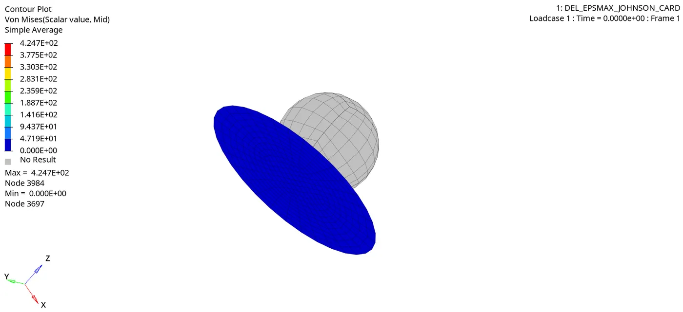
- Max stress induced = 424 Mpa
Strain contour results
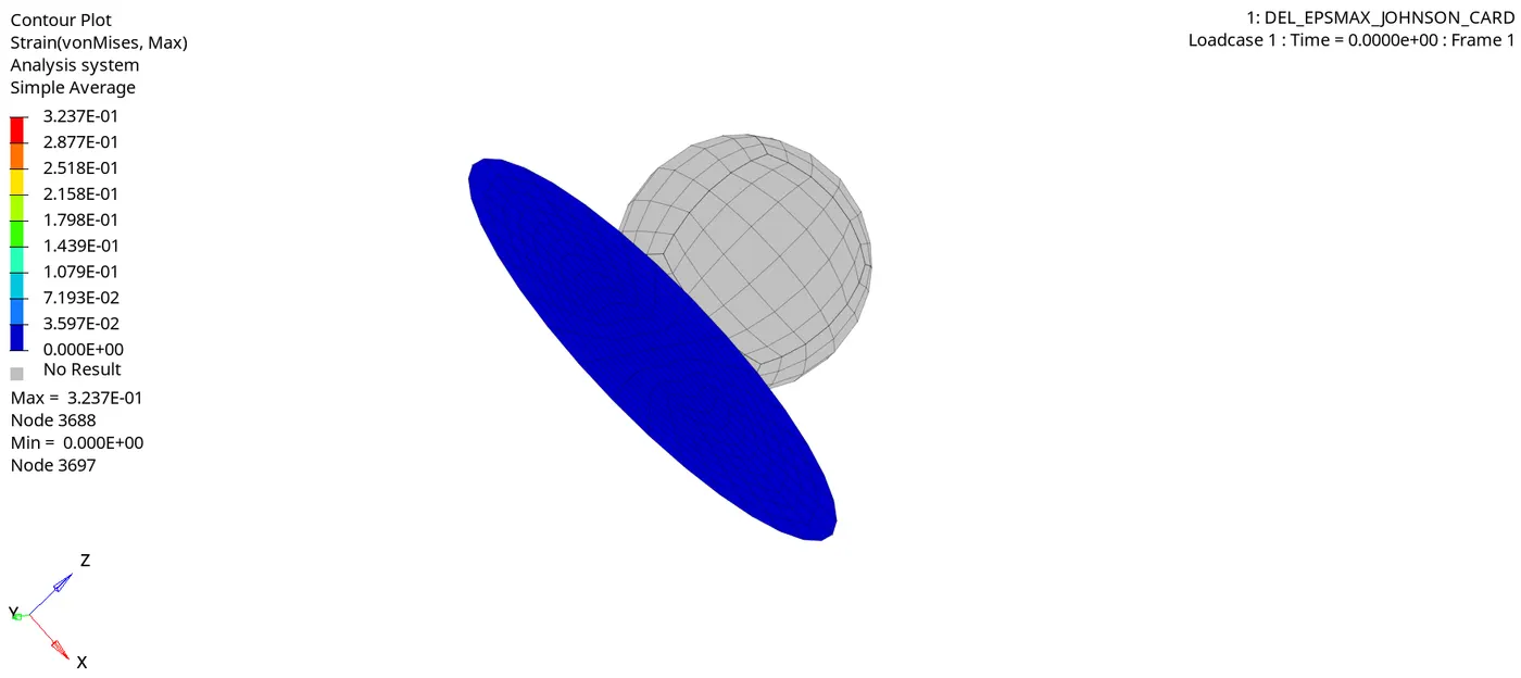
Max strain = 0.323
2a) Plot of the Rigid Wall Forces.
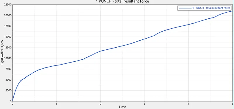
- Max punch resultant force = 21030 N.
A. Kinetic Energy
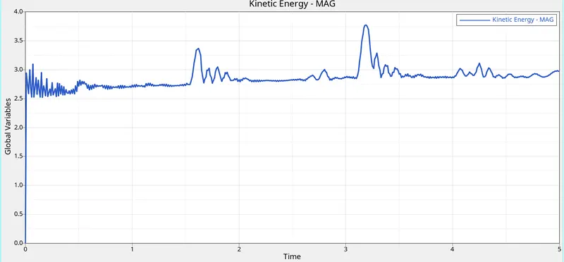
- Max kinetic energy = 3.77 gm (mm /ms)²
B. Internal energy
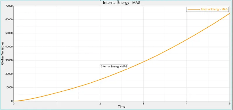
- Max internal energy = 64665 gm (mm /ms²)
C. Contact energy
D. hourglass energy
E. Total energy
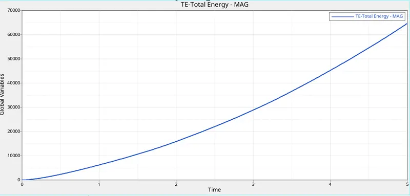
Max total energy = 64668 gm (mm /ms²)
CASE 5: To convert the material model to Law1 elastic with same mechanical properties.
- Import the case 4 rad file and perform the simulation by changing the material card to Law 1. Keep the same value for rho, E, and nu values.
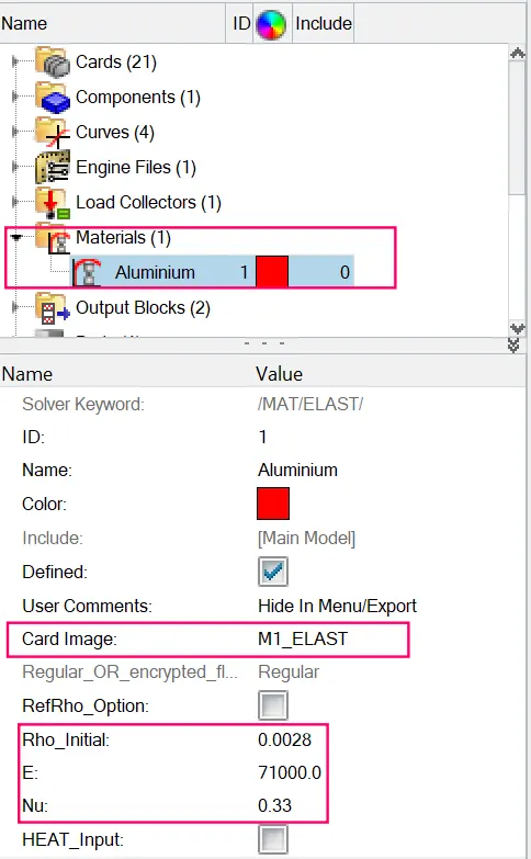
STEP 1 : RADIOSS Job
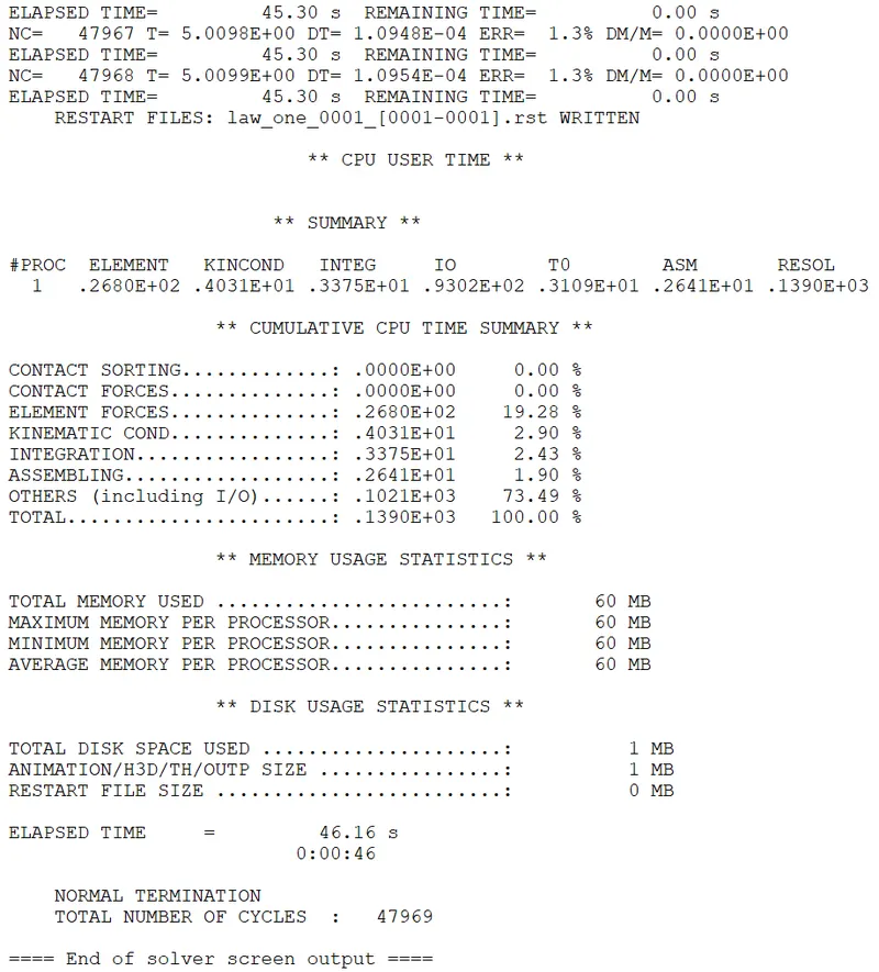
STEP 2 : Check errors.
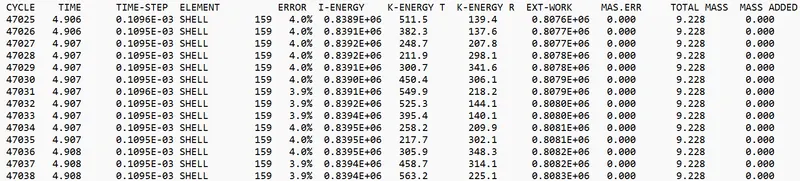
Maximum energy error = 4.0 %
Maximum kinetic energy = 3.77 gm (mm /ms)²
Maximum internal energy = 64665 gm (mm /ms²)
Max mass error = 0
STEP 10 : Post processing
1) Review the Simulation using -HyperView.
Stress contour results
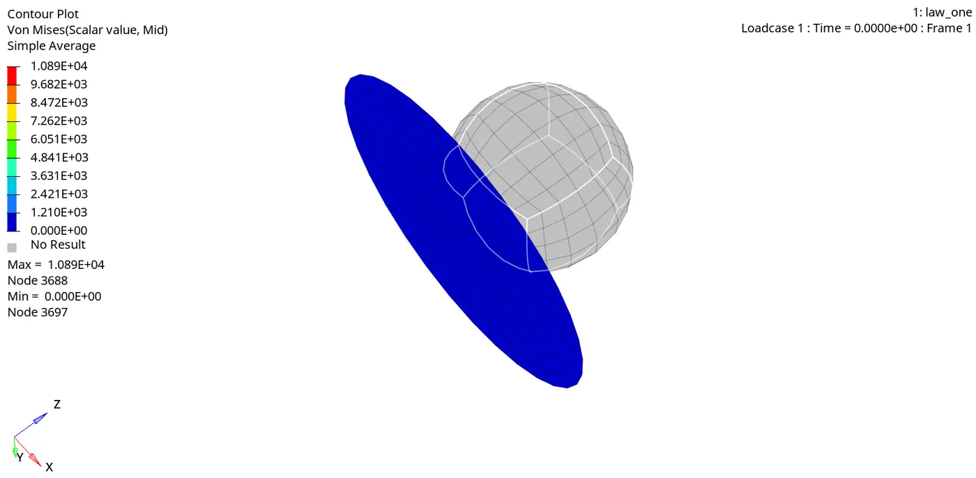
- Max stress induced = 1089 Mpa.
Strain contour results
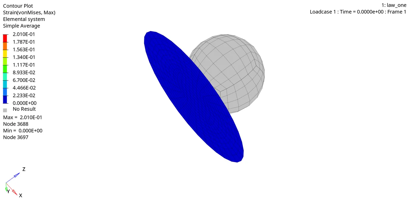
Max strain induced = 0.201
a) Plot of the Rigid Wall Forces.
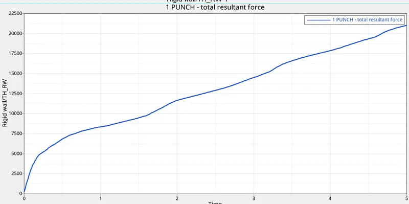
- Max punch resultant force = 21030 N.
A. Kinetic Energy
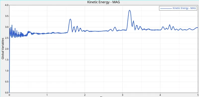
- Max kinetic energy = 3.77 gm (mm /ms)²
B. Internal energy
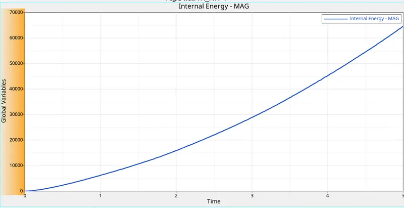
- Max internal energy = 64665 gm (mm /ms²)
C. Contact energy
D. hourglass energy
E. Total energy
Max total energy = 64668 gm (mm /ms²).
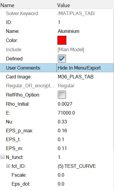
CASE 6 : Change the material card to Law 36 material card.
- In this case we have to import the required file i.e. LAW27_0000. It is an isentropic elasto-plastic material using user defined functions for the work hardening portion of the stress-strain curve for a different strain.
- Import the case 1 rad file, named “Law2_epsmax_failure” and perform the simulation with the law 36 material card. Refer to the video titled "Materials 7" for further information.
Step 1: Creation of curve
- To create a Curve, Right Click on the Model Browser > Create > Curve > Window Will Pop Up > Define a Curve using Platic Strains and Post-Yield Stress Values.
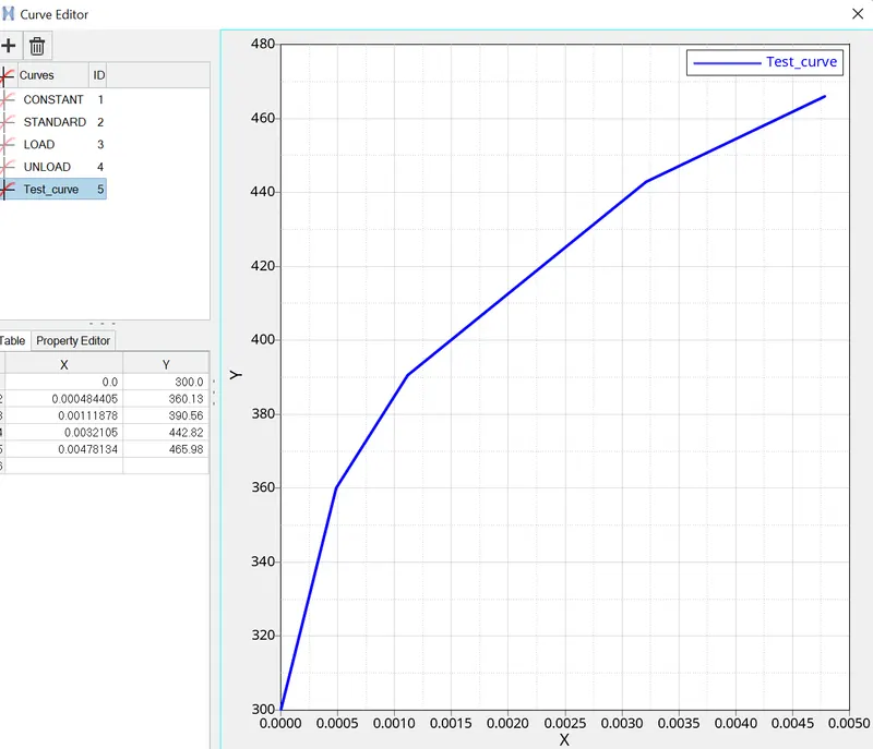
STEP 2 : RADIOSS Job
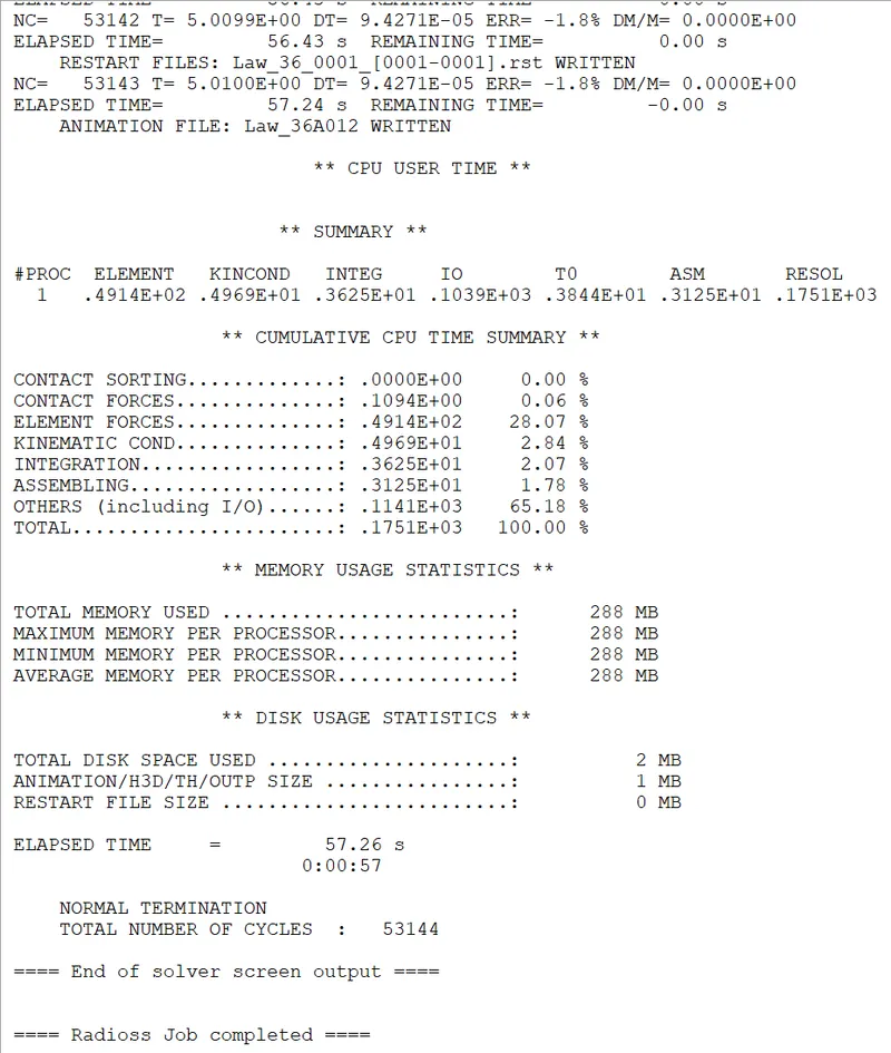
STEP 3 : Check errors.
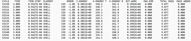
Maximum energy error = 1.8 %
Maximum kinetic energy = 3.77 gm (mm /ms)²
Maximum internal energy = 64665 gm (mm /ms²)
Max mass error = 0
STEP 4 : Post processing
1) Review the Simulation using -HyperView.
Stress contour results
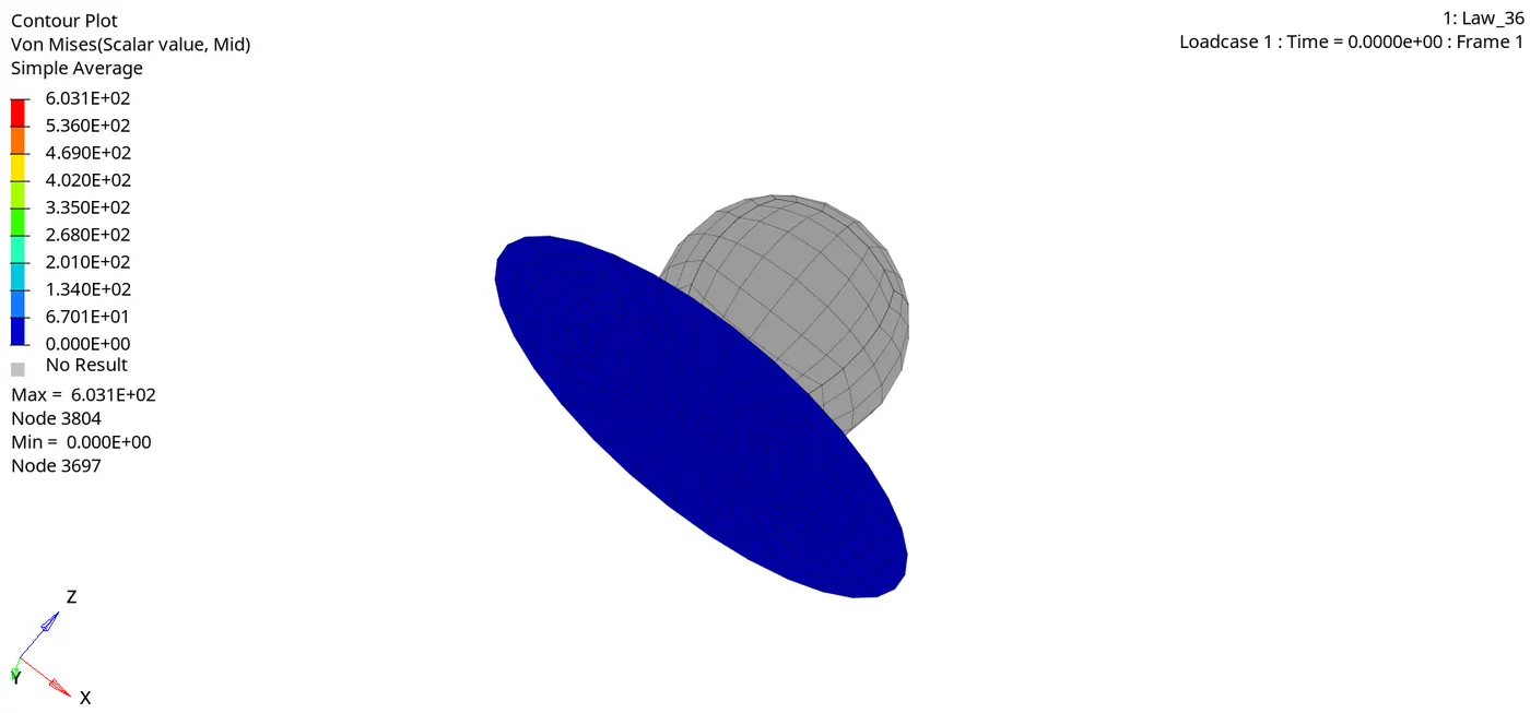
- Max stress induced = 1089 Mpa.
Strain contour results
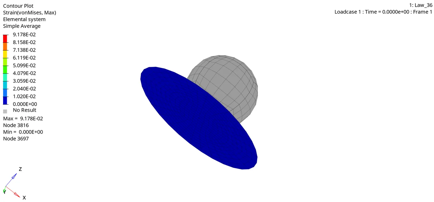
- Strain = 0.09
a) Plot of the Rigid Wall Forces.
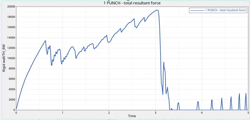
- Max punch resultant force = 19384 N.
b) Internal energy
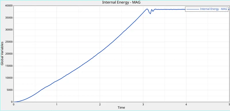
- Max internal energy = 64665 gm (mm /ms²)
c) Kinetic Energy
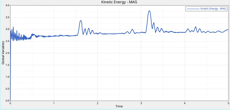
- Max kinetic energy = 3.77 gm (mm /ms)².
d) Contact energy
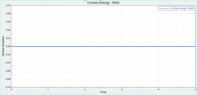
e) hourglass energy
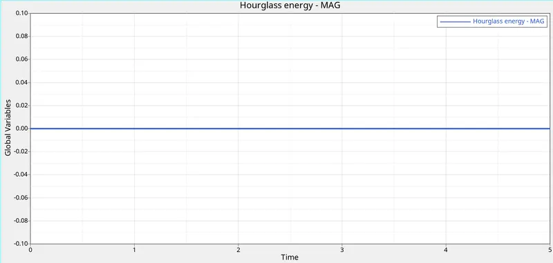
f.) Total energy
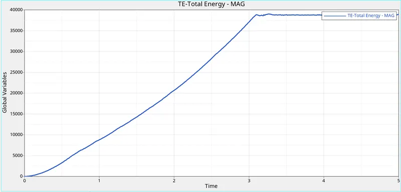
- Total energy = 39005 gm (mm /ms²)
Case 7 : Law 27 material card
- Open the Law27_0000.rad file and perform the simulation with the law 27 material card. Use the recommended shell properties.
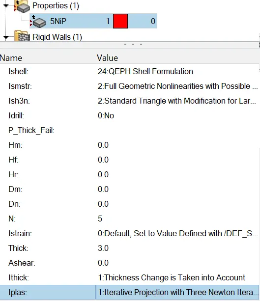
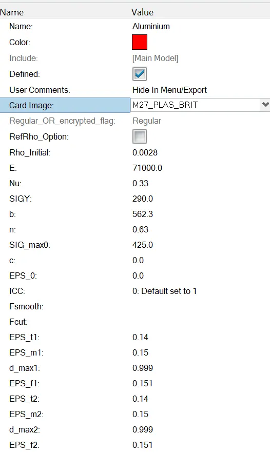
STEP 2 : RADIOSS Job
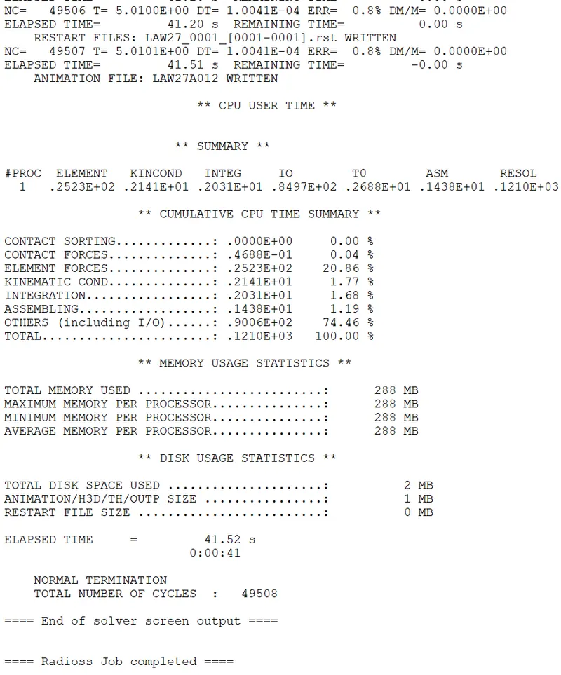
STEP 3 : Check errors.
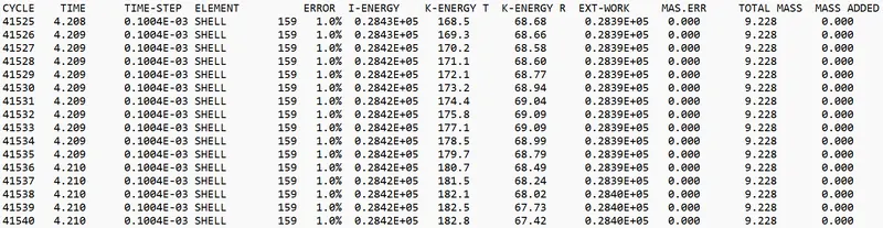
Maximum energy error = 1.0 %
Maximum kinetic energy = 425.88 gm (mm /ms)²
Maximum internal energy = 29476 gm (mm /ms²)
Max mass error = 0
STEP 4 : Post processing
1) Review the Simulation using -HyperView.
Stress contour results
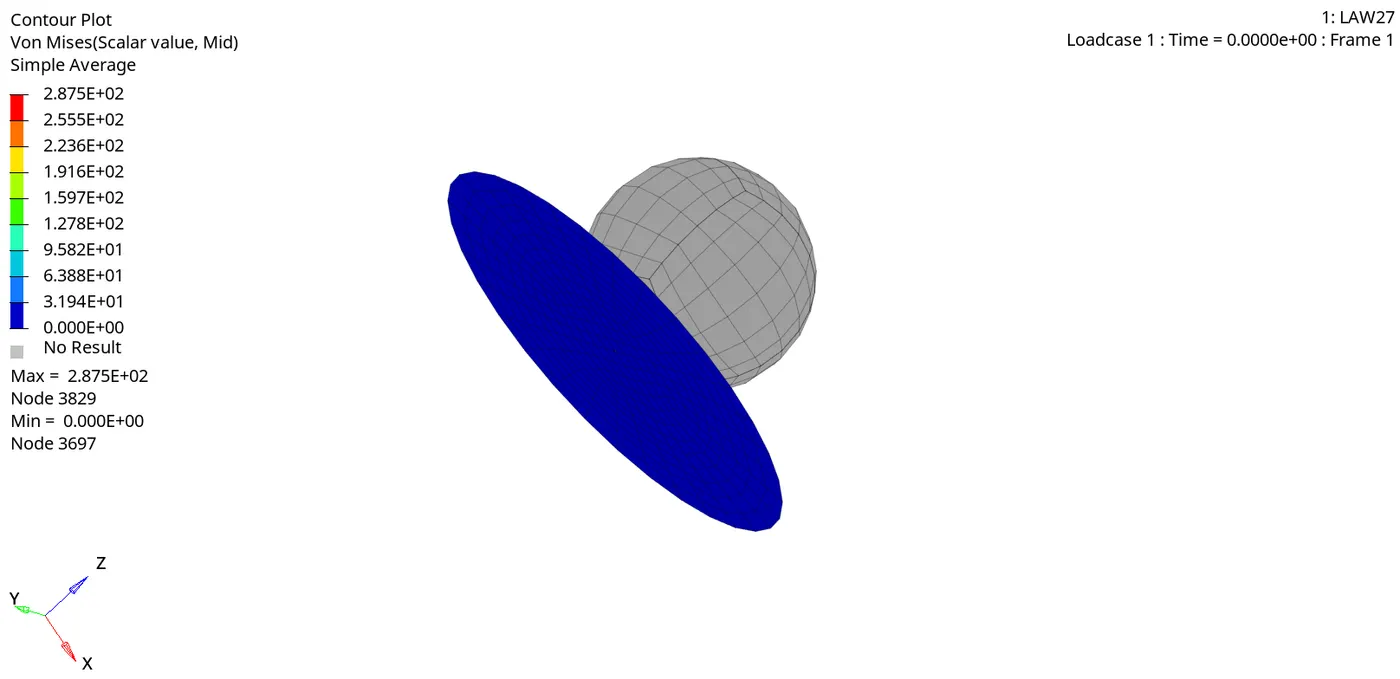
Max stress induced = 287.5 Mpa
Strain contour results
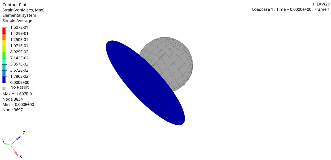
Max strain = 0.1607
a) Plot of the Rigid Wall Forces.
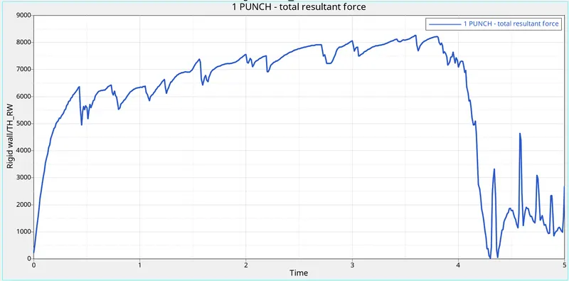
Max punch resultant force = 8256.72 N.
b) Internal energy
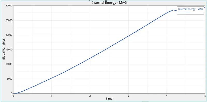
- Max internal energy = 29476 gm (mm /ms²)
c) Kinetic Energy
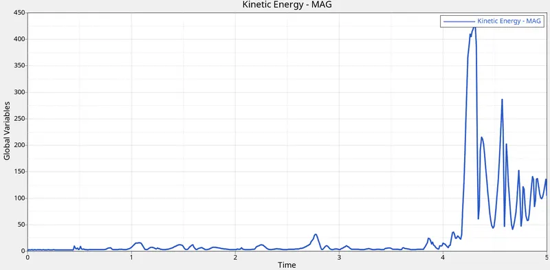
- Max kinetic energy = 425.88 gm (mm /ms)².
d) Contact energy
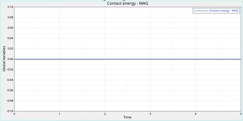
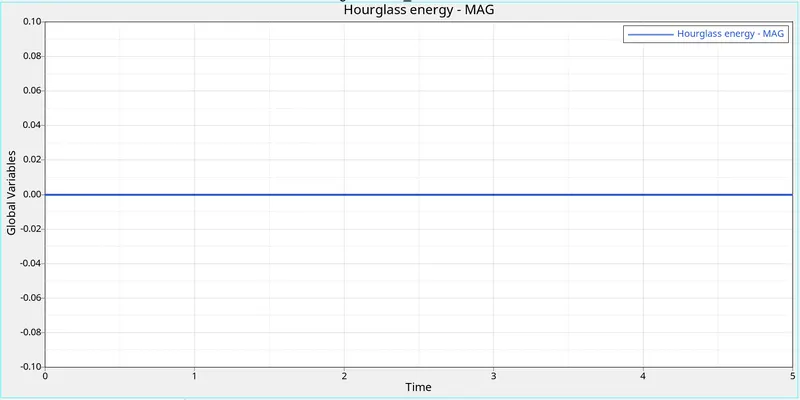
e) hourglass energy
f.) Total energy
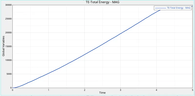
- Total energy = 29581 gm (mm /ms²)
COMPARISON OF ALL 7 CASES RESULTS :
| S.no | Description | LAW2_epsmax failure | Law2_epsmax_crack | Law2_epsmax_no fail | Law2_epsmax_no fail_remove johnson & eps max card | Law1 material card | Law 36 material card | Law 27 material card |
| INPUT DATAS | ||||||||
| 1. | Material Card | M2_PLAS_JOHNS_ZERIL | M2_PLAS_JOHNS_ZERIL | M2_PLAS_JOHNS_ZERIL | M2_PLAS_JOHNS_ZERIL | M1_ELAST | M_36_PLAS_TAB | M27_BLAS_BRIT |
| 2. | Failure Johnson card Datas | yes | Yes | No | No | No | Yes | No |
| 3. | Ifail_sh | 2: for each integration points the stress tensor is set to zero | 1:Default shell is deleted or cracked | - | - | - | 2: for each integration points the stress tensor is set to zero | - |
| 4. | Dadv | 0 | 1 | - | - | - | 0 | - |
| 5. | Ixfem | 0 | 1: XFEM formulation | - | - | - | 0 | - |
| 6. | Ishell | 24:QEPH shell formulation. | 24:QEPH shell formulation. | 24:QEPH shell formulation. | 24:QEPH shell formulation. | 24:QEPH shell formulation. | 24:QEPH shell formulation. | 24:QEPH shell formulation. |
| 7. | Ismstr | 2:Full geometric non linearities with small strain possible small strain formulation activation | 2:Full geometric non linearities with small strain possible small strain formulation activation | 2:Full geometric non linearities with small strain possible small strain formulation activation | 2:Full geometric non linearities with small strain possible small strain formulation activation | 2:Full geometric non linearities with small strain possible small strain formulation activation | 2:Full geometric non linearities with small strain possible small strain formulation activation | 2:Full geometric non linearities with small strain possible small strain formulation activation |
| 8. | Ish3n | 2: standard triangle with modification for large rotation | 2: standard triangle with modification for large rotation | 2: standard triangle with modification for large rotation | 2: standard triangle with modification for large rotation | 2: standard triangle with modification for large rotation | 2: standard triangle with modification for large rotation | 2: standard triangle with modification for large rotation |
| 9. | No of integration points (N ) | 5 | 5 | 5 | 5 | 5 | 5 | 5 |
| 10. | Ithick | 1:Thickness change is taken into account | 1:Thickness change is taken into account | 1:Thickness change is taken into account | 1:Thickness change is taken into account | 1:Thickness change is taken into account | 1:Thickness change is taken into account | 1:Thickness change is taken into account |
| 11. | Iplas | 1:Iterative projection with three newton iterations | 1:Iterative projection with three newton iterations | 1:Iterative projection with three newton iterations | 1:Iterative projection with three newton iterations | 1:Iterative projection with three newton iterations | 1:Iterative projection with three newton iterations | 1:Iterative projection with three newton iterations |
| 12. | Al-Initial Density(ρi) | 0.0028 gm /mm³. | 0.0028 gm /mm³. | 0.0028 gm /mm³. | 0.0028 gm /mm³. | 0.0028 gm /mm³. | 0.0028 gm /mm³. | 0.0028 gm /mm³. |
| 13. | Youngs modulus(E) | 71000 Mpa | 71000 Mpa | 71000 Mpa | 71000 Mpa | 71000 Mpa | 71000 Mpa | 71000 Mpa |
| 14. | Poissons ratio(ν) | 0.33 | 0.33 | 0.33 | 0.33 | 0.33 | 0.33 | 0.33 |
| 15. | Yield stress(σy ) | 290 Mpa | 290 Mpa | 290 Mpa | 290 Mpa | - | - | 290 Mpa |
| 16. | Plastic hardening parameter (b) | 562 Mpa | 562 Mpa | 562 Mpa | 562 Mpa | - | - | 562 Mpa |
| 17. | Plastic hardening exponent (n) | 0.63 | 0.63 | 0.63 | 0.63 | - | - | 0.63 |
| 18. | Tensile failure strain(m) | - | - | - | - | - | 0.1 | - |
| 19. | Tensile failure strain(t) | - | - | - | - | - | 0.11 | - |
| 20. | Failure plastic strain(EPS_p_max) | 0.151 | 0.151 | 0.151 | 0 | - | 0.16 | 0.151 |
| 21. | Maximum stress (SIG_Max0) | 425 | 425 | 425 | 425 | - | - | 425 |
| OUTPUT DATAS | ||||||||
| 1. | Elapsed time(secs) | 44.97 | 38.87 | 39 | 42.52 | 46.16 | 57.26 | 41.52 |
| 2. | No of cycles | 49380 | 49217 | 49408 | 48737 | 47969 | 53144 | 49508 |
| 3. | Max punch force (N) | 8408 | 8310 | 8174 | 21030 | 21030 | 19384 | 8256 |
| 4. | Max internal energy gm (mm /ms²) | 27322 | 30812 | 27443 | 64665 | 64665 | 38642 | 29476 |
| 5. |
Max kinetic energy gm (mm /ms)² |
179.25 | 210 | 232 | 3.77 | 3.77 | 3.77 | 426 |
| 6. | Hour glass energy | 0 | 0 | 0 | 0 | 0 | 0 | 0 |
| 7. | Contact energy | 0 | 0 | 0 | 0 | 0 | 0 | 0 |
| 8. | Total energy | 27375 | 30953 | 27528 | 64668 | 64668 | 39005 | 29581 |
| 9. | Max energy error | 1.3% | 4.5% | 1.2% | 3% | 4% | 1.8% | 1% |
| 10. | Mass error | 0 | 0 | 0 | 0 | 0 | 0 | 0 |
| 11. | Max stress (Mpa) | 275 Mpa | 293 | 270 | 424 | 1089 | 1089 | 287.5 |
| 12. | Max strain | 0.140 | 0.147 | 0.135 | 0.323 | 0.201 | 0.091 | 0.1607 |
| 13. | Element behaviour | Elements are deleted | Elements are cracked and deleted. | Elements are deleted | Elements are deformed, cracked but not deleted. | Elements are deformed, cracked but not deleted. | Elements are deleted | Elements are deleted |
Result :
- Hence the simulation for all the cases were carried out with different materials laws.
- Hence the simulation for all the cases were runned successfully.
- Hence the simulation for all the cases were reviewed by hyperview.
- Hence the graphs were plotted for all the cases successfully.
- Atlast,Compared all the results for those cases.
Conclusion and Learning Outcome :
- I conclude that LAW 36 is more suitable in real world testings, cause it shows the behaviour of Elasticity and Plasticity in real world.
- In this challenge,I came to know bout
- The different materials cards and their behaviour.
- The failure criteria for the material cards.
- How the deformation is happening for the elements from material cards.
- How to define a plastic region curve with plastic starin and post-yield stress values.