Week 5 Challenge : Surface wrap on Automotive Assembly
Surface Wrap on Automotive Assembly
AIM
In this project, the whole engine, gearbox, and transmission parts will be fixed, using all the topo tools provided by ANSA; likewise, the components named will be merged to be finally meshed. The parts provided by the challenge have a lot of errors and undesired surfaces that must be determined and deleted, using different ANSA methods that have been shown in previous projects, after that, each component will be joined by using the merge function and finally, it will be introduced a new meshing tool whose main function is to generate a mesh over different body external components; this kind of meshing method is so used for preparing FEM models (Finite Element Methods).
OBJECTIVES
Fix the damaged surfaces that the initial body components have and delete the undesired surfaces that are left over.
Join the components one by one and close the holes that remain exposed after the assembly, to guarantee the external meshing will not get enough deformations caused by these holes.
Put the mesh over the component joint by using the wrap meshing function provided by ANSA. Besides that, use the mesh-cell side size stated by the challenge to perform the external mesh.
Demonstrate the mesh effectiveness by showing the internal components from the components have been neglected by the meshing function used.
ENGINEERING DEVELOPMENT
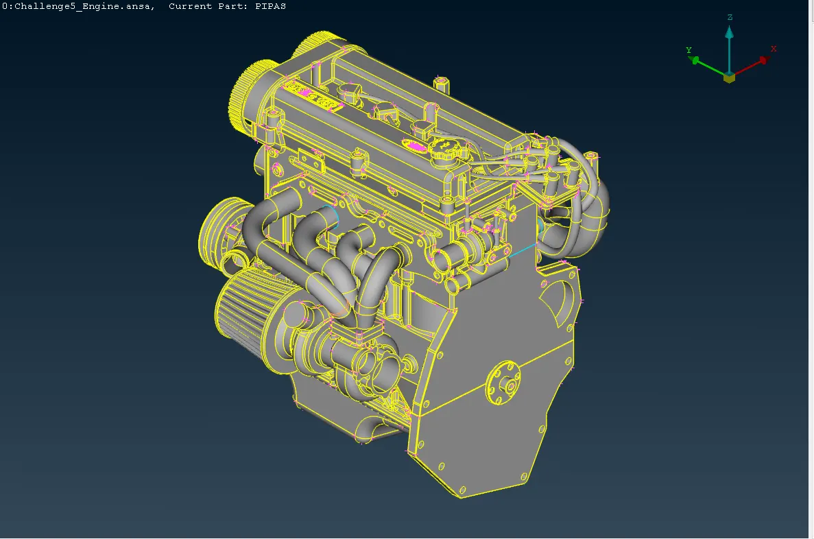
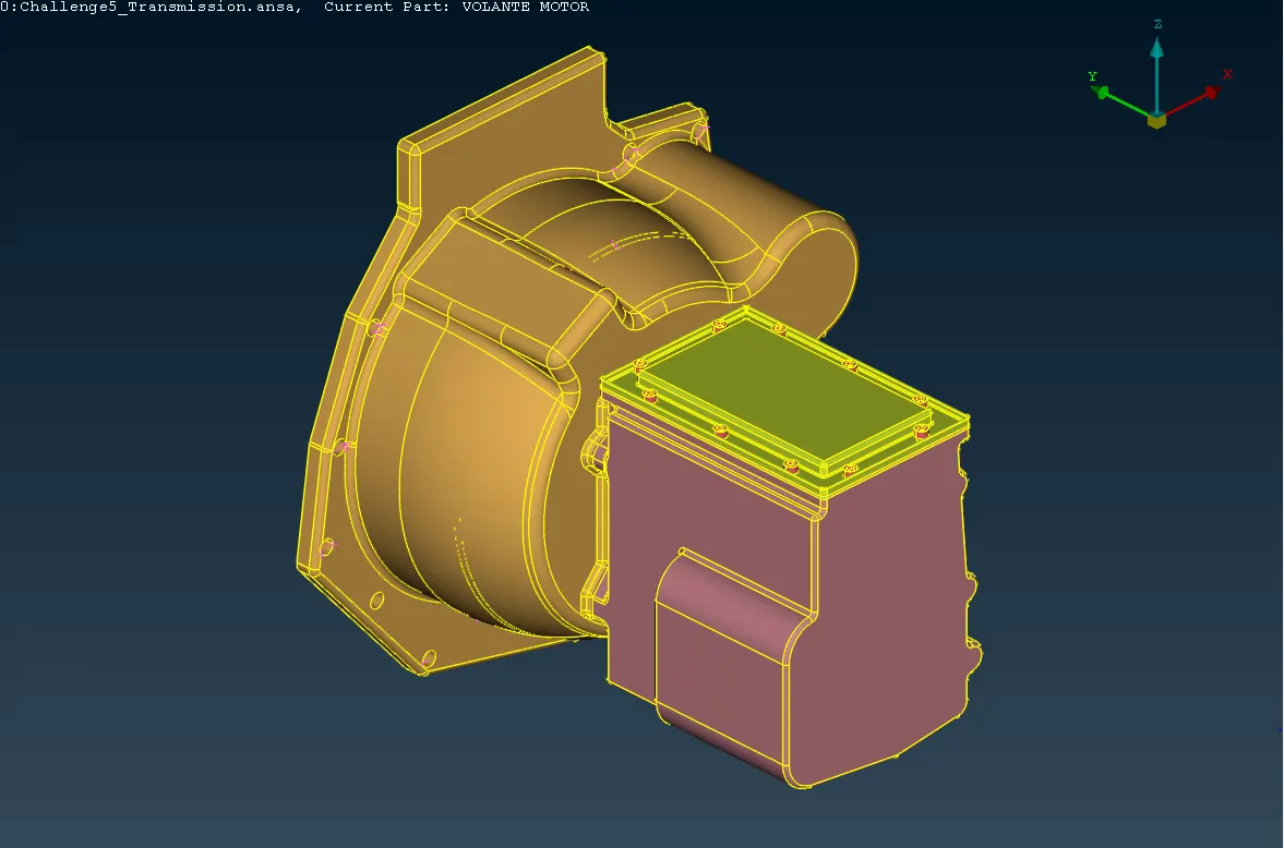
The first step in this process is to delete the surfaces named above and fix the desired surfaces that have some errors or single cons; this process will be alike the previous projects that are referenced below. The finishing of the components by repairing all these are:
- Finishing of the engine
- Finishing of the transmission box
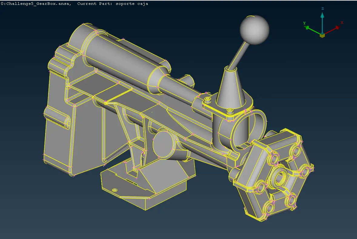
- Finishing of the gearbox
Then, the repaired components must be merged; this process is achieved by using the merge function which is located in the file icon as is shown in the following picture.
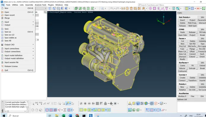
The merge function will address the user to the folder where the main component open in the computer is saved, due to that, the other components must also be saved in the same folder.
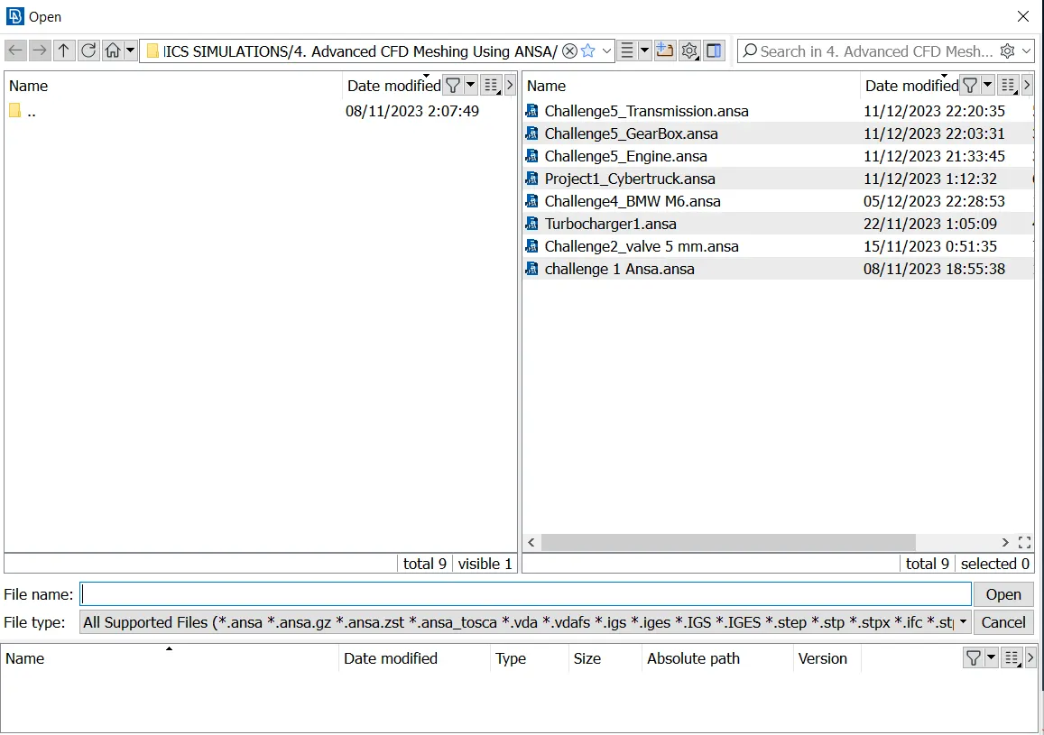
If all the components are located in the same folder and these are correctly opened, ANSA software will fit the components automatically as is shown below.
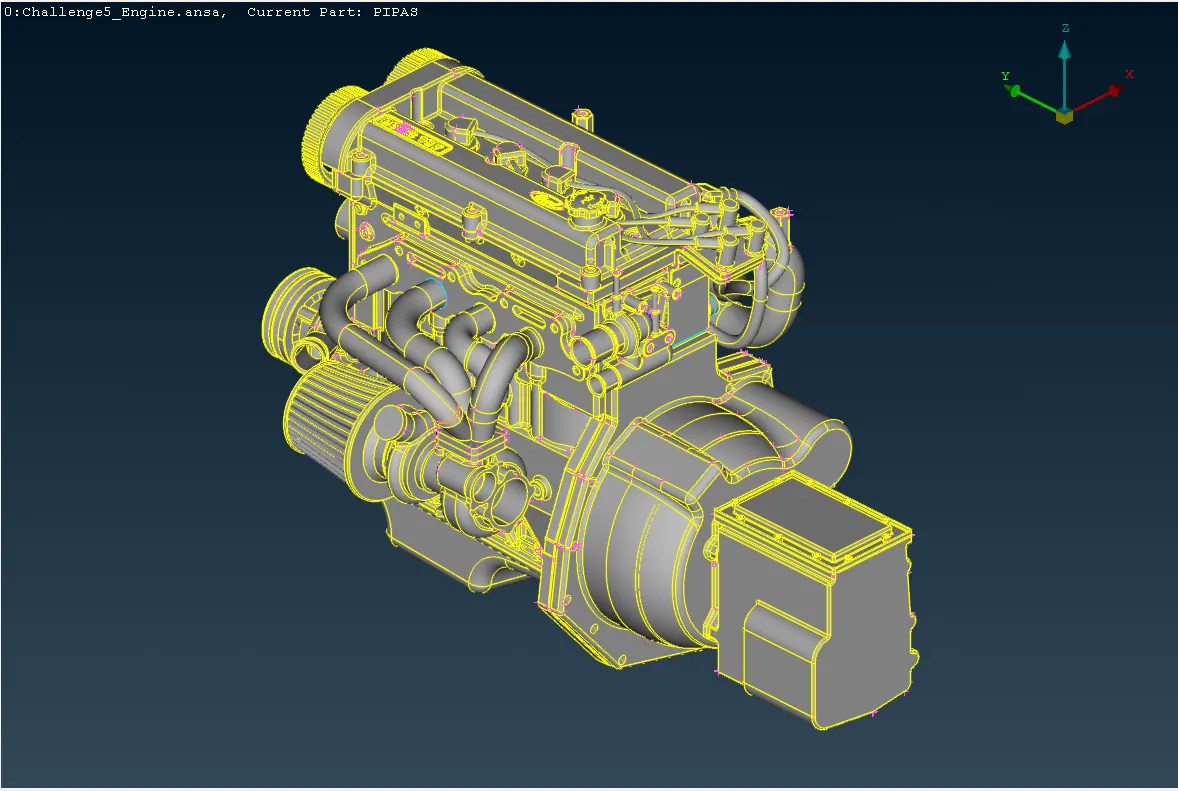
By repeating the same process, the remaining component is also updated and fitted automatically along the components.
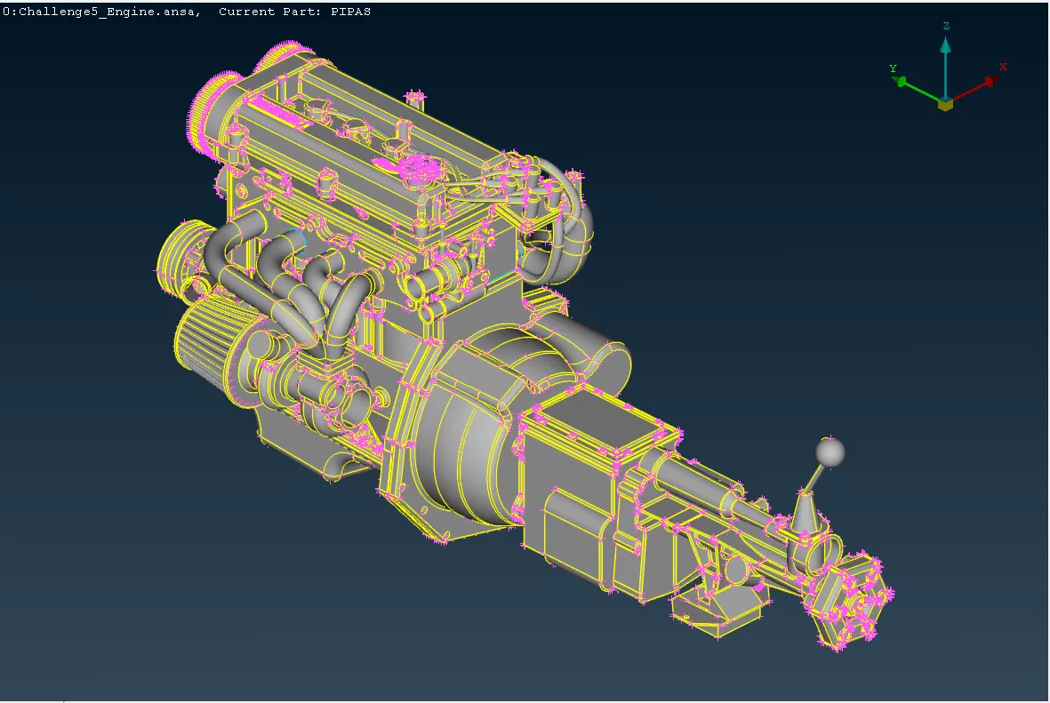
Once the merge process is completed, the next step is to close the holes of the whole components. Using the surface components can create new surfaces around the hole edges; In the next four images, the enclosure hole process over the engine holes is shown.
- Engine holes enclosure:
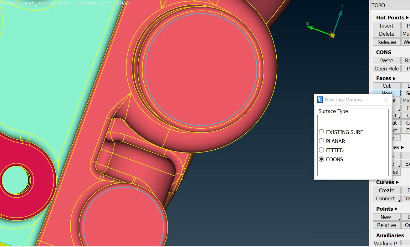
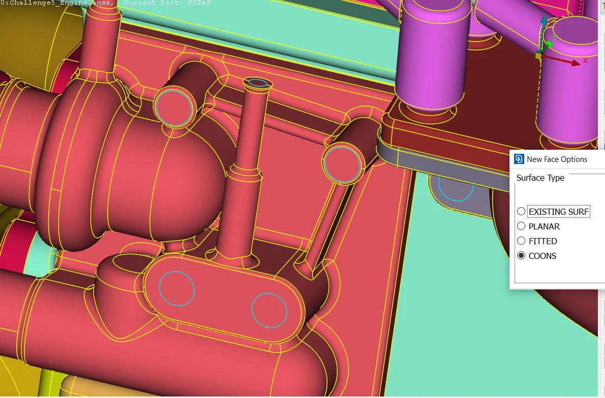
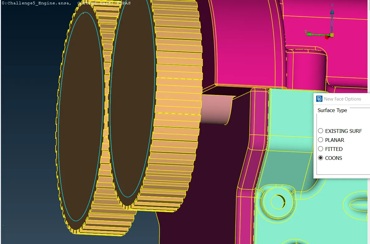
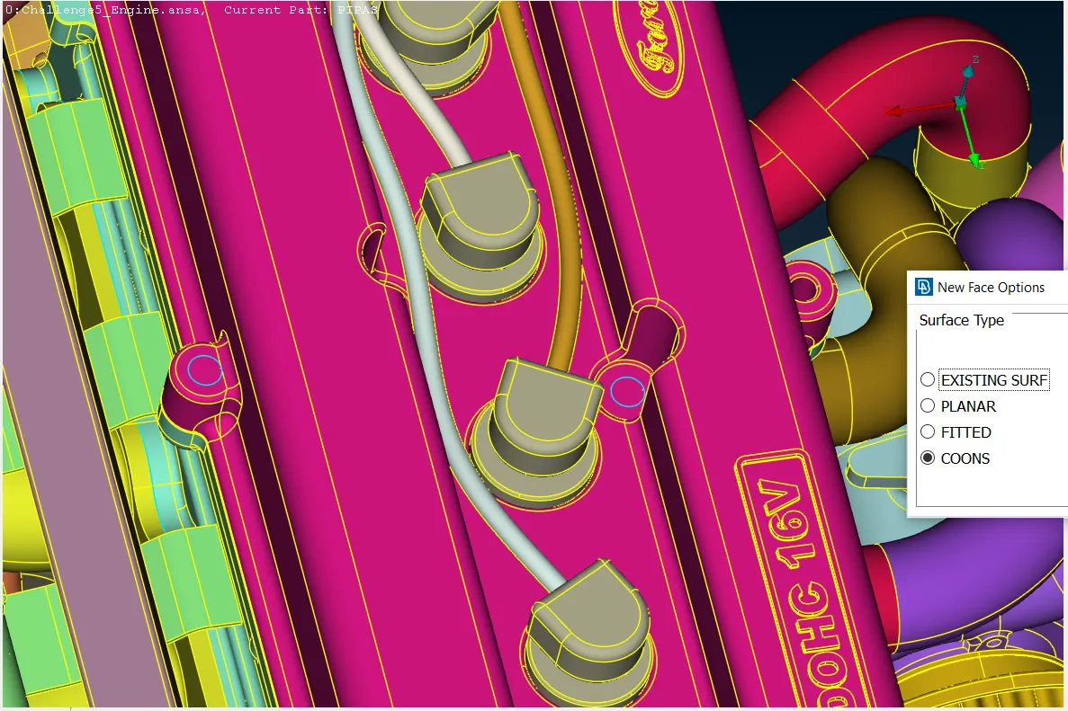
Likewise, the enclosure process in the other parts must also be performed.
- Transmission holes enclosure:
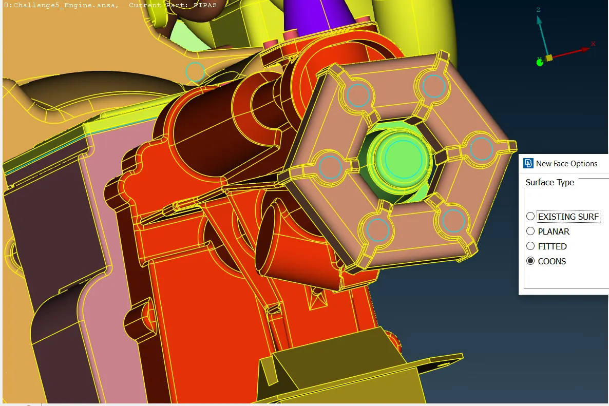
Thus, the meshing process can be carried out now. The picture below shows the function location that will be used to mesh the whole components together. The wrap is a meshing function provided by ANSA that takes the exposed surfaces shown and meshes them as an alone component.
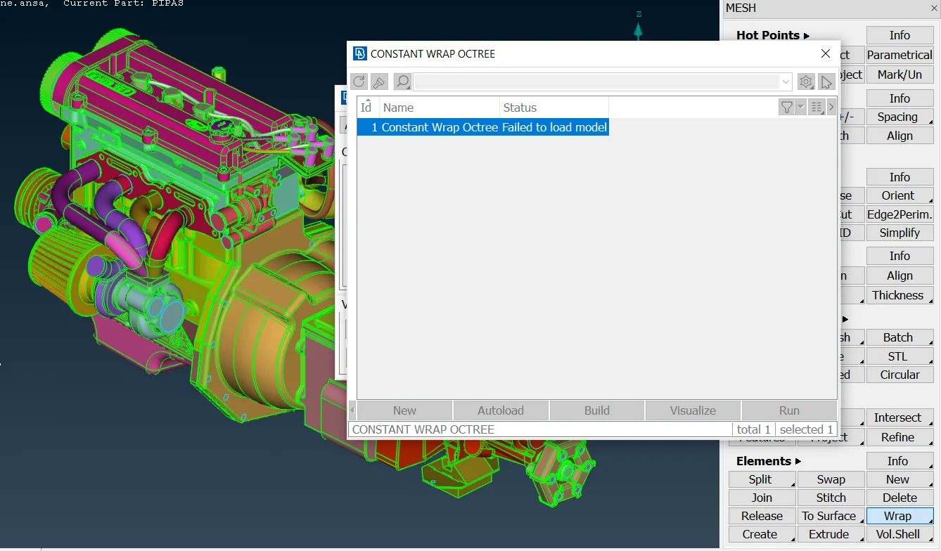
The wrap function shows the parameters that are plotted below; these parameters must be selected one by one for the user.
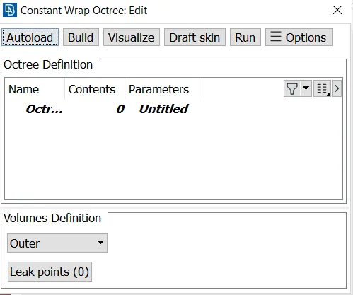
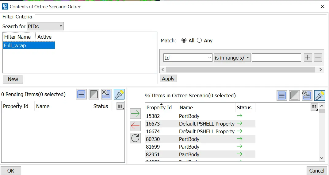
The first parameter is the contents, which are the main surfaces that will be entered in order to carry out the wrap meshing. This section will take the PID components that the PID box has, however, to make sure the PID components selected are not empty, it must be used compress function, which deletes the empty components that the PID section has. Then, the remaining PID components must be moved from the left side section to the right side section.
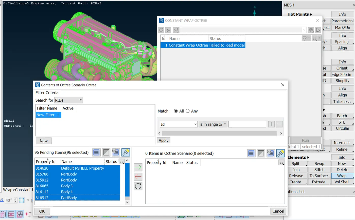
In the picture below shows components movement described.
Finally, the target length that the mesh cell side size will have, is entered in the parameters section shown in the previous box thrown by the wrap function.
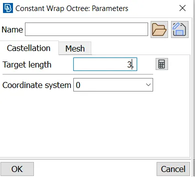
The contents section is named Full_wrap and the parameters as a Target, so that the wrap meshing can be run now.
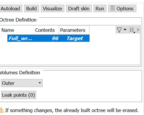
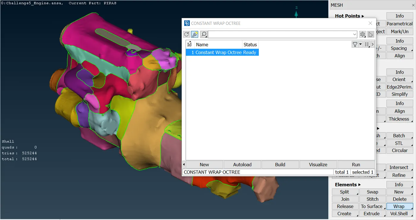
If the function running is correct, the main wrap box will display an advisement in the status section that says "Ready". That means the meshing has been completed and has not got any single error.
RESULTS
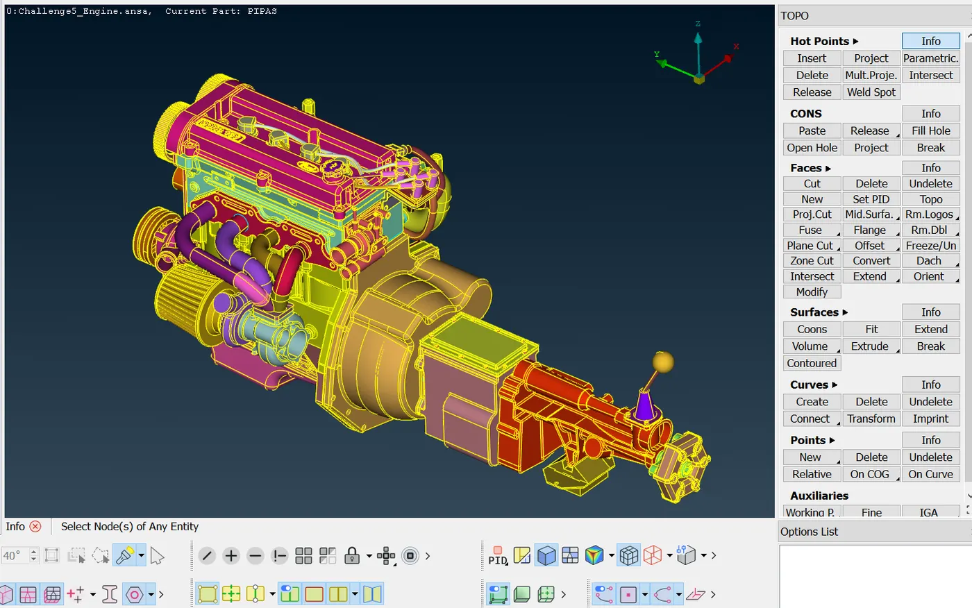
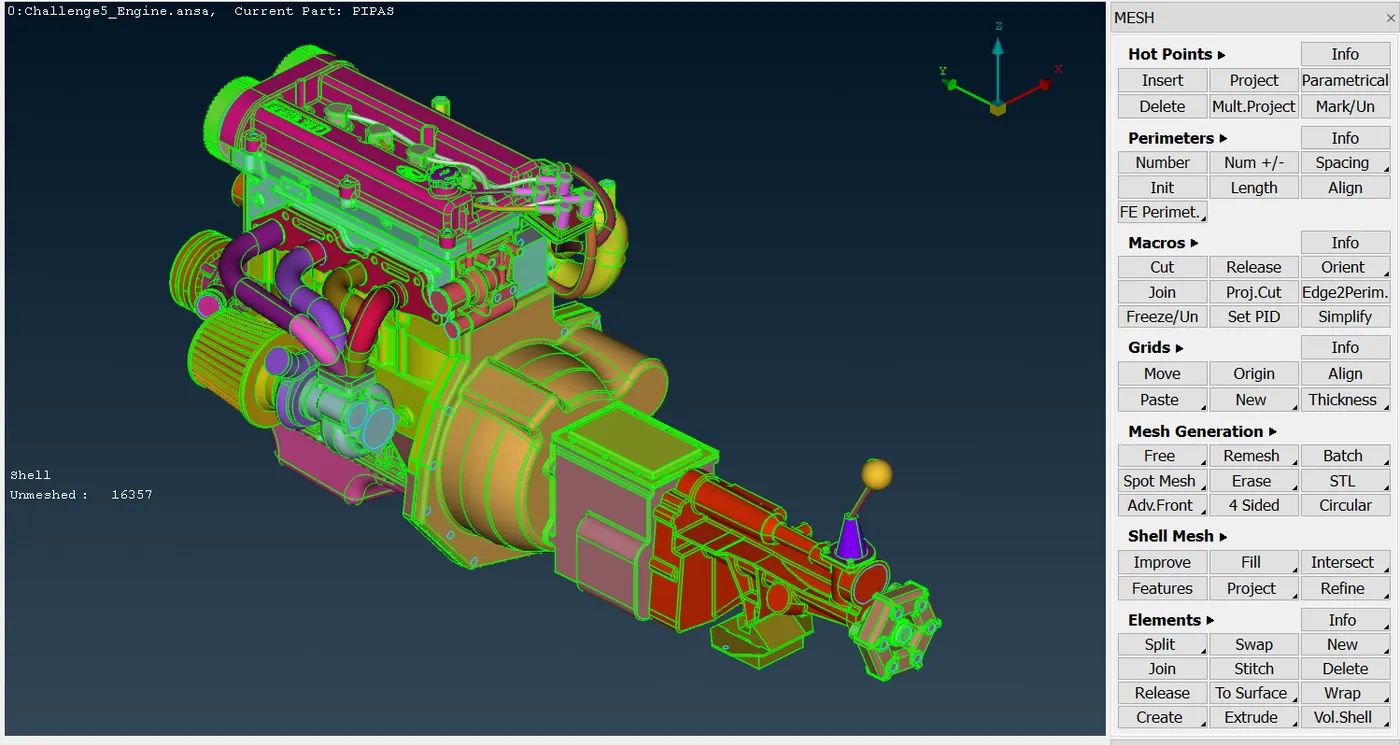
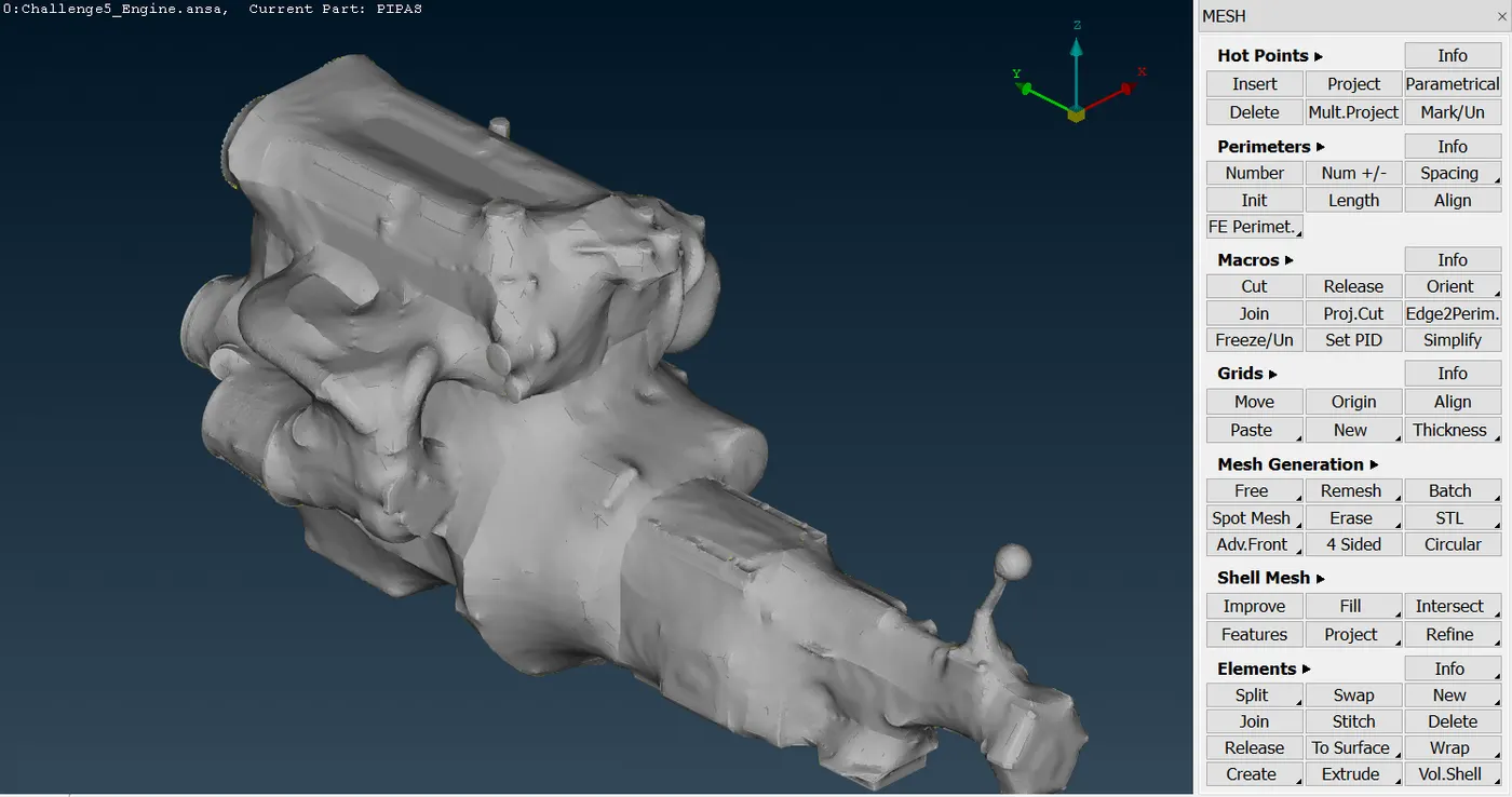
The first image shows the final result of the components repaired and merged.
- Components repaired and merged
The second picture shows the initial meshing section, including all the holes closed.
- Initial component meshing with holes closed
Finally, the next four pictures show in different angles and sections, that the finishing of the meshing was successful.
- Finishing of the components meshing on the front view
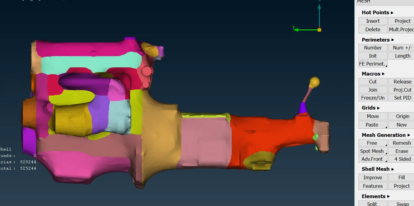
- Finishing of the meshing - cut out that shows the neglecting of the inner parts
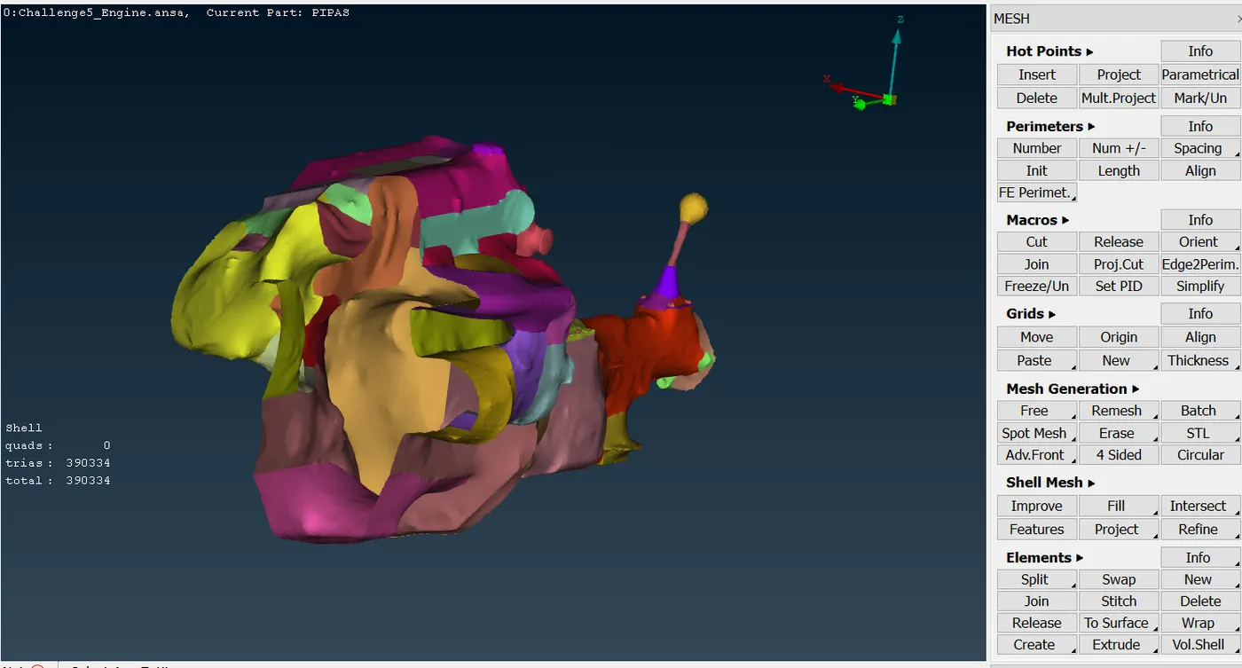
- Finishing of the meshing - cut out that shows the neglecting of the inner parts - right view
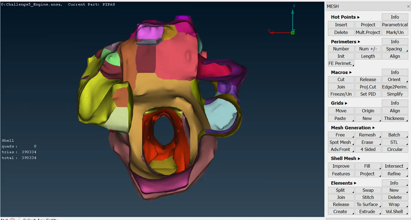
- Finishing of the meshing - isometric view
Using the target length stated by the challenge, the number of elements obtained is shown in the following table.
| Components | Number of elements |
| Reciprocant Engine - Transmission - Gearbox | 525244 |
CONCLUSIONS
The fixing of complex structures or components with a high number of parts can take too long time even from using software programs, because the software methods sometimes do not take errors and the user has to consider them before performing the meshing.
The wrap meshing function is a useful function that ANSA provides, however, depending on the geometrical finishing that the user requires, this method takes too much time to get the mesh. So, it is necessary to have a high-performance computer if the user wants to obtain meshes with low mesh cell side sizes in a short time.
REFERENCES
https://skill-lync.com/student-projects/week-2-challenge-surface-meshing-on-a-pressure-valve-451
https://skill-lync.com/student-projects/week-3-challenge-cfd-meshing-on-turbocharger-411
https://skill-lync.com/student-projects/week-4-challenge-cfd-meshing-for-bmw-car-366