Week 12 - Validation studies of Symmetry BC vs Wedge BC in OpenFOAM vs Analytical H.P equation
Validation studies of Symmetry BC vs Wedge BC in OpenFOAM vs Analytical H.P equation
AIM
The following project is a continuation of the Week 11 project previously carried out (project link attached on References). In this project will be updated the radius values, calculating the boundary points that are changed by the wedge angle variation (to understand what is the wedge angle please review Week 11 challenge) ; once the wedge boundaries have been updated, it will be reviewed the velocity, pressure and shear stress wall behavior along the pipe.
OBJECTIVES
Update the wedge boundaries with determined angles in order to check how the flow behaves along the pipe and the flow changes.
Determine the velocity, pressure and shear stress wall changes along the pipe using OpenFoam software.
Plot the results for each wedge angle variation.
ENGINEERING DEVELOPMENT
Previously in the Week 11 project, it was developed the flow analysis through a lineal pipe without any ground angle. In this project will only be updated the geometry points to create the axi-symetric geometry and then, the simulation will be ran up. Using the MATLAB code attached as at the final of this section as the final of this project, the OpenFoam blockMeshDict will be updated for 10, 25 and 45 wedge angle deegrees. Then, the geometry will look like:
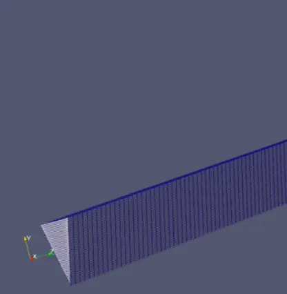
Cross section geomtry is bigger than the cross section geometry obtained for 5 degrees, which looks like:
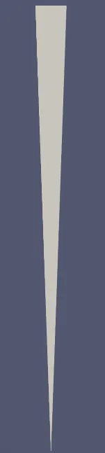
So, in the first sight it could be thought the mesh at 10, 25 or 45 degrees will be less accurate than at 5 degrees. However, the results will confirm if this primary assumption is right or not. The MALTAB code written before is:
MATLAB blockMeshDict UPDATING CODE:
%Week 11 - Simulation of Flow through a pipe in OpenFoam
%Engr. Diego Alejandro Cepeda Cuartas

%In this challenge, you will simulate an axi-symmetric flow by applying the
% wedge boundary condition. The flow is laminar and flows through a constant
% cross-section pipe at an inlet Reynold's number of 2100. You can do a
% transient or steady state simulation and you will validate your results
% with the Hagen- Poiseuille's equations for the fully developed flow.

%You will also write code in Matlab to automate the generation of
% blockMeshDict file. The code should take inputs like pipe length,
% diameter, wedge angle, etc and output a fully functional blockMeshDict
% file.

%Expected Results

%Validate Hydro-dynamic length with the numerical result
%Validate the fully developed flow velocity profile with its analytical profile
%Validate maximum velocity and pressured drop for fully developed flow
%Post-process Shear stress and validate wall shear stress for fully developed flow

%Hint

%You can create a wedge from a hex block by collapsing its bottom face
% (by merging both sets of adjacent vertices)
%Wedge angle should be less than 5 degrees
%You can assume the pipe diameter

%SOLUTION:
%CODE:

clear all
close all
clc

%STEP 1. Geometry features
% Diameter of Pipe (m)
d = 0.025;

% Radius of Pipe (m)
r = d/2;

% Reynold's Number
Re = 2100;

% Wedge Angle (degrees)
theta = 5;

% Total Length of the Pipe (m)
L = 2.8;


% Assuming working fluid is water at 25° C
% Density of water (kg/m³)
rho = 998.21;

% Dynamic Viscosity of Water (Pa.s)
mu = 1.002 * 10^-3;

% Kinematic Viscosity of Water (m^2/s)
nu = mu/rho;


% Hydrodynamic Entrance Length (m)
L_h = 0.06 * Re * D;


% STEP 2. Initial & Boundary conditions
% Hagen - Pousielle's flow equation
V_avg = (mu * Re)/(rho * D); % Average Velocity (m/s)

V_max = 2 * V_avg; % Maximum Velocity (m/s)

delta_p = (32*mu*V_avg*L)/(D^2); % Pressure Drop (Pa)

kinematic_delta_p = delta_p/rho; % Kinematic Pressure Drop (Pa)

% STEP 3. Defining OpenFoam requirements

% Vertices
V0 = [0 0 0];
V1 = [0 R*cosd(theta/2) -R*sind(theta/2)];
V2 = [0 R*cosd(theta/2) R*sind(theta/2)];

V3 = [L 0 0];
V4 = [L R*cosd(theta/2) -R*sind(theta/2)];
V5 = [L R*cosd(theta/2) R*sind(theta/2)];


% BLOCKMESHDICT FILE
% Creating the file
% Header
h1 = '/*--------------------------------*- C++ -*----------------------------------*\';
h2 = '  =========                 |';
h3 = '  \\      /  F ield         | OpenFOAM: The Open Source CFD Toolbox';
h4 = '   \\    /   O peration     | Website:  https://openfoam.org';
h5 = '    \\  /    A nd           | Version:  9';
h6 = '     \\/     M anipulation  |';
h7 = '\*---------------------------------------------------------------------------*/';
h8 = 'FoamFile';
h9 = '{';
h10 = '    format      ascii;';
h11 = '    class       dictionary;';
h12 = '    object      blockMeshDict;';
h13 = '}';
h14 = '// * * * * * * * * * * * * * * * * * * * * * * * * * * * * * * * * * * * * * //';


% Creating BlockMesh File
f1 = fopen('blockMeshDict.txt','w');

% Header
fprintf(f1,'%s\n',h1);
fprintf(f1,'%s\n',h2);
fprintf(f1,'%s\n',h3);
fprintf(f1,'%s\n',h4);
fprintf(f1,'%s\n',h5);
fprintf(f1,'%s\n',h6);
fprintf(f1,'%s\n',h7);
fprintf(f1,'%s\n',h8);
fprintf(f1,'%s\n',h9);
fprintf(f1,'%s\n',h10);
fprintf(f1,'%s\n',h11);
fprintf(f1,'%s\n',h12);
fprintf(f1,'%s\n',h13);
fprintf(f1,'%s\n\n',h14);

% Conversion Factor
fprintf(f1,'%s\n\n','convertToMeters 1;');

% Vertices
fprintf(f1,'%s\n','vertices');
fprintf(f1,'%s\n','(');
fprintf(f1,'\t(%d %d %d)\n',V0);
fprintf(f1,'\t(%d %f %f)\n',V1);
fprintf(f1,'\t(%d %f %f)\n',V2);
fprintf(f1,'\t(%.2f %d %d)\n',V3);
fprintf(f1,'\t(%.2f %f %f)\n',V4);
fprintf(f1,'\t(%.2f %f %f)\n',V5);
fprintf(f1,'%s\n\n',');');

% Blocks
fprintf(f1,'%s\n','blocks');
fprintf(f1,'%s\n','(');
fprintf(f1,'\thex (0 3 4 1 0 3 5 2) (400 30 1) simpleGrading (1 0.1 1)\n');
fprintf(f1,'%s\n\n',');');

% Edges
fprintf(f1,'%s\n','edges');
fprintf(f1,'%s\n','(');
fprintf(f1,'\tarc 2 1 (%d %.3f %d)\n',0,R,0);
fprintf(f1,'\tarc 5 4 (%.3f %.3f %d)\n',L,R,0);
fprintf(f1,'%s\n\n',');');

% Boundary
fprintf(f1,'%s\n','boundary');
fprintf(f1,'%s\n','(');

% Axis
fprintf(f1,'\taxis\n');
fprintf(f1,'\t{\n');
fprintf(f1,'\t\ttype empty;\n');
fprintf(f1,'\t\tfaces\n');
fprintf(f1,'\t\t(\n');
fprintf(f1,'\t\t\t(0 3 3 0)\n');
fprintf(f1,'\t\t);\n');
fprintf(f1,'\t}\n\n');

% Inlet
fprintf(f1,'\tinlet\n');
fprintf(f1,'\t{\n');
fprintf(f1,'\t\ttype patch;\n');
fprintf(f1,'\t\tfaces\n');
fprintf(f1,'\t\t(\n');
fprintf(f1,'\t\t\t(0 1 2 0)\n');
fprintf(f1,'\t\t);\n');
fprintf(f1,'\t}\n\n');

% Outlet
fprintf(f1,'\toutlet\n');
fprintf(f1,'\t{\n');
fprintf(f1,'\t\ttype patch;\n');
fprintf(f1,'\t\tfaces\n');
fprintf(f1,'\t\t(\n');
fprintf(f1,'\t\t\t(3 5 4 3)\n');
fprintf(f1,'\t\t);\n');
fprintf(f1,'\t}\n\n');

% Front Face
fprintf(f1,'\tfront\n');
fprintf(f1,'\t{\n');
fprintf(f1,'\t\ttype wedge;\n');
fprintf(f1,'\t\tfaces\n');
fprintf(f1,'\t\t(\n');
fprintf(f1,'\t\t\t(0 3 4 1)\n');
fprintf(f1,'\t\t);\n');
fprintf(f1,'\t}\n\n');

% Back Face
fprintf(f1,'\tback\n');
fprintf(f1,'\t{\n');
fprintf(f1,'\t\ttype wedge;\n');
fprintf(f1,'\t\tfaces\n');
fprintf(f1,'\t\t(\n');
fprintf(f1,'\t\t\t(0 2 5 3)\n');
fprintf(f1,'\t\t);\n');
fprintf(f1,'\t}\n\n');

% Top Wall
fprintf(f1,'\tpipeWall\n');
fprintf(f1,'\t{\n');
fprintf(f1,'\t\ttype wall;\n');
fprintf(f1,'\t\tfaces\n');
fprintf(f1,'\t\t(\n');
fprintf(f1,'\t\t\t(1 4 5 2)\n');
fprintf(f1,'\t\t);\n');
fprintf(f1,'\t}\n');

fprintf(f1,'%s\n\n',');');
fprintf(f1,'%s\n','mergePatchPairs');
fprintf(f1,'%s\n','(');
fprintf(f1,'%s\n\n',');');
fprintf(f1,'%s\n','// ************************************************************************* //');
RESULTS
Velocity
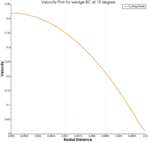
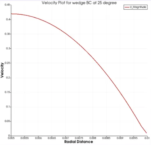
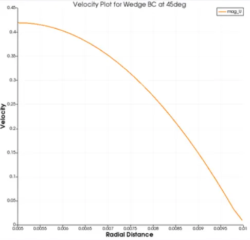
The velocity profile along the cross section of the geometry gets a bit less loose regarding the wedge angle is increased, this loosing lost can be seen in the following three images:
- At 10 degrees of angle wedge:
- At 25 degrees of wedge angle:
- At 45 degrees of angle edge:
Pressure
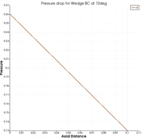
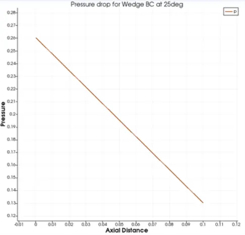
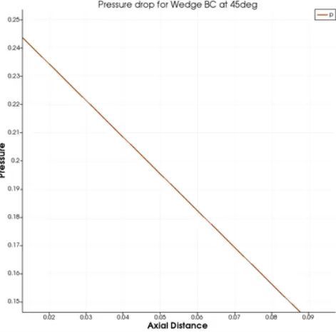
Likewise, the pressure drop decreases at the tip of the pipe's cross section, also due to the wedge angle increasing. The net three pictures shows how the pressure drop decreases in each simulation:
- At 10 degrees of wedge angle:
- At 25 degrees of wedge angle:
- At 45 degrees of wedge angle:
Shear stress over the wall
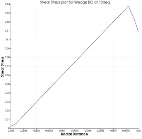
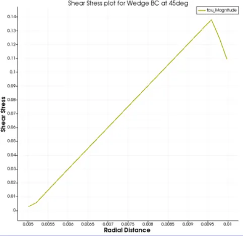
Finally, the shear stress along the pipe cross section looks alike in the both three simulations, however, the plot peak gains a little movement to the left such as the shear stress along the cross section would have occured before the analysis had been performed on the pipe wall.
- At 10 degrees of wedge angle:
- At 25 degrees of wedge angle:

- At 45 degrees of wedge angle:
CONCLUSIONS
The assumption given in before obtaining the results is accomplished due to the accurate is less certain once the wedge angle is increased; However, the simulation results still keep the simulation stable and the CFL number does not seem affected by the wedge increasing, determining the wedge geometry could have a good interaction in CFD simulations without presenting mesh issues or badly mistakes on the simulation.
These kind of meshes also are commonly used to determine the loads and strains along a solid material (FEA).
That's it, thanks for reading. (WEEK 11 PROJECT LINK IS ATTACHED IN THE NEXT PART OF THE PRESENT PROJECT)
REFERENCES
https://skill-lync.com/student-projects/week-11-simulation-of-flow-through-a-pipe-in-openfoam-383