Week 2 Challenge : Surface meshing on a Pressure valve
Surface meshing on a pressure valve
AIM
The following project concerns the surface corrections and meshing of a pressure valve geometry. A pressure valve provided by the challenge statements will be fixed using the ANSA tools for topological corrections and then, once the whole surfaces from the valve geometry have been fixed, it will be developed three different meshes, which will have the same shape, however, their side length will be different for each mesh case.
OBJECTIVES
Fix the surface error that the component has, according to the ANSA model provided by the challenge statements.
Simulate the mesh over the pressure valve section to see the fittest mesh and the most appropriate way for meshing the component.
ENGINEERING DEVELOPMENT
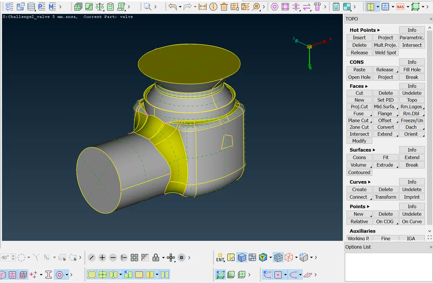
Using the tools provided on "Faces", the initial errors that the geometry has, can be fixed and deleted. Then, the fixed geometry will look like the picture shown below.
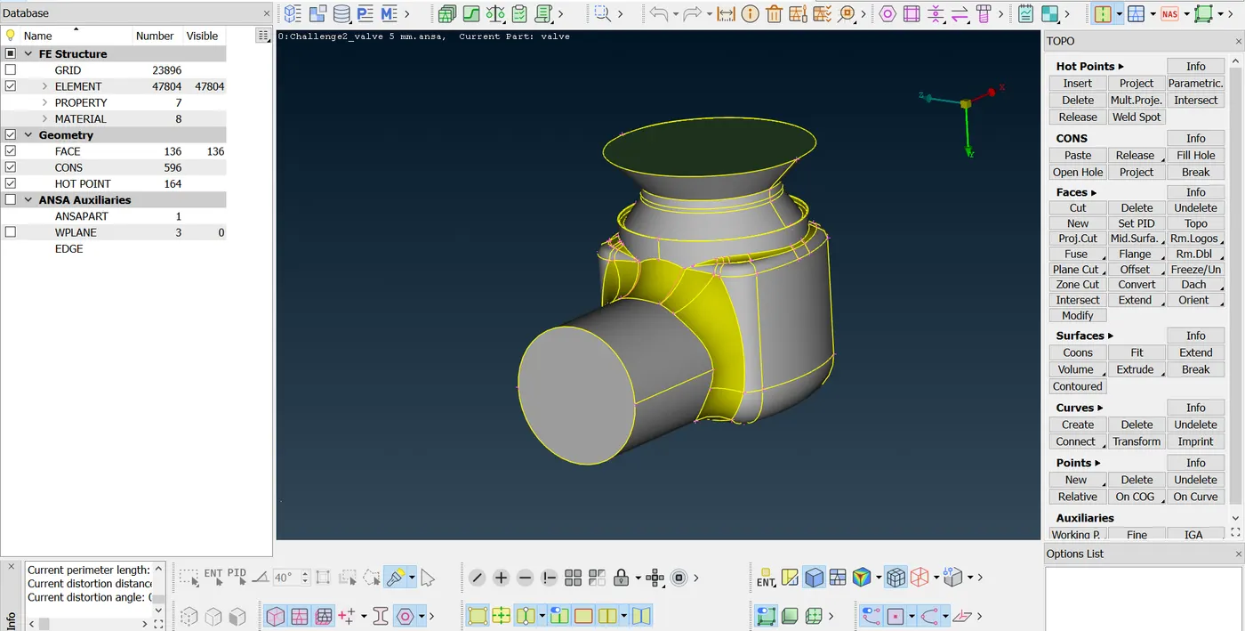
Likewise, to get an accurate mesh with no bad divisions, the lines created on the surface fixing must be suppressed; to do that, it is also necessary to use the "Delete" icon so that the new surface is used above. To make sure the lines are not taken into account by the meshing, the lines have to appear in orange color.
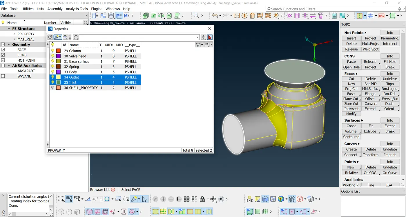
Also, to define the sub-components of which the pressure valve is divided, it is used PID tool which serves for naming different surfaces to add them in a new section where they can be taken as a sub-assembly from the entire pressure valve structure. The image below shows different new components created on ANSA, however, the ones that can be watched are specifically the inlet, outlet, and pressure valve body.
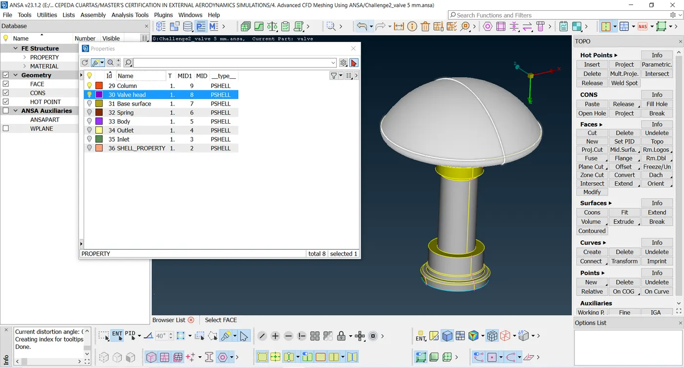
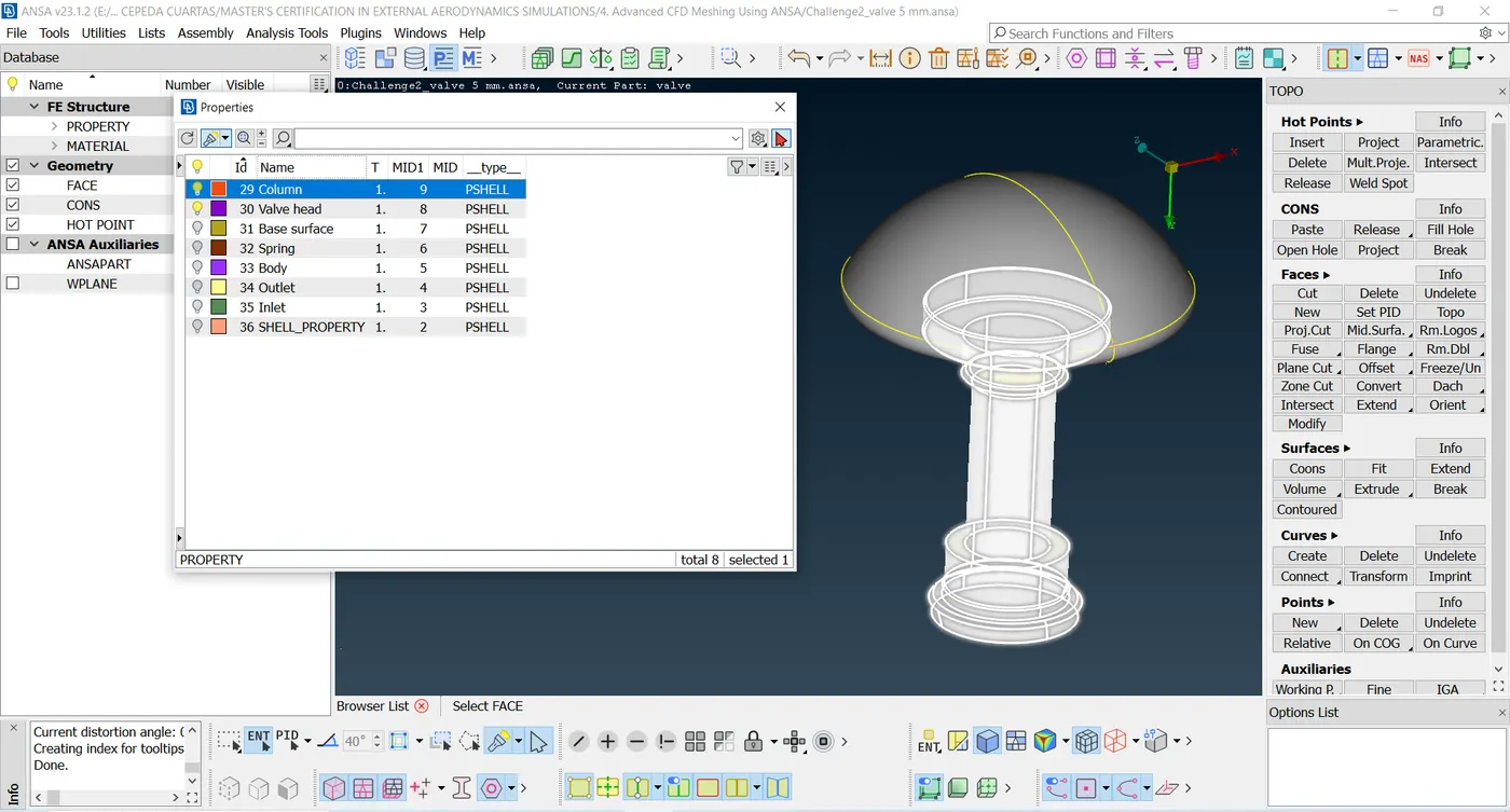
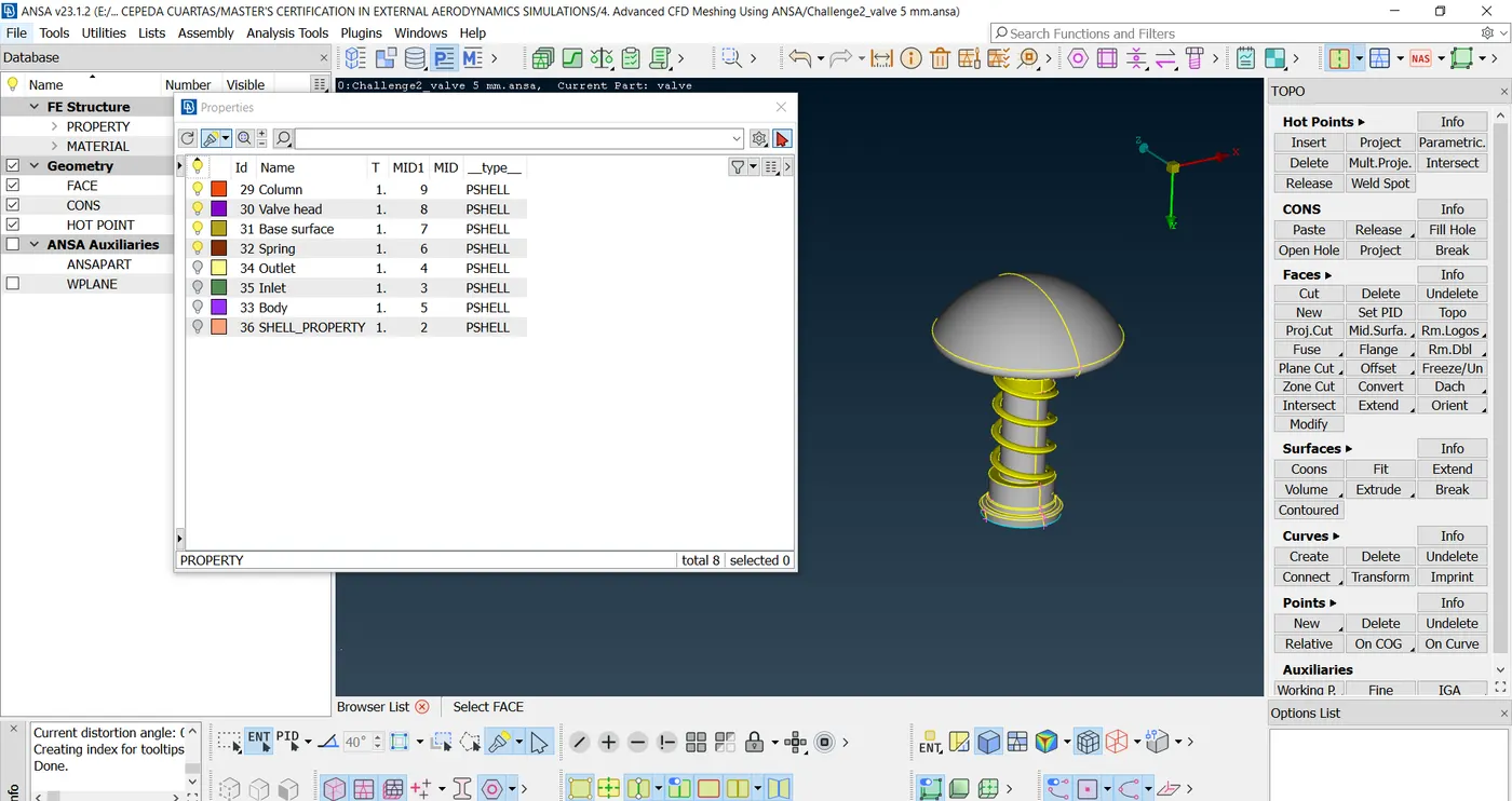
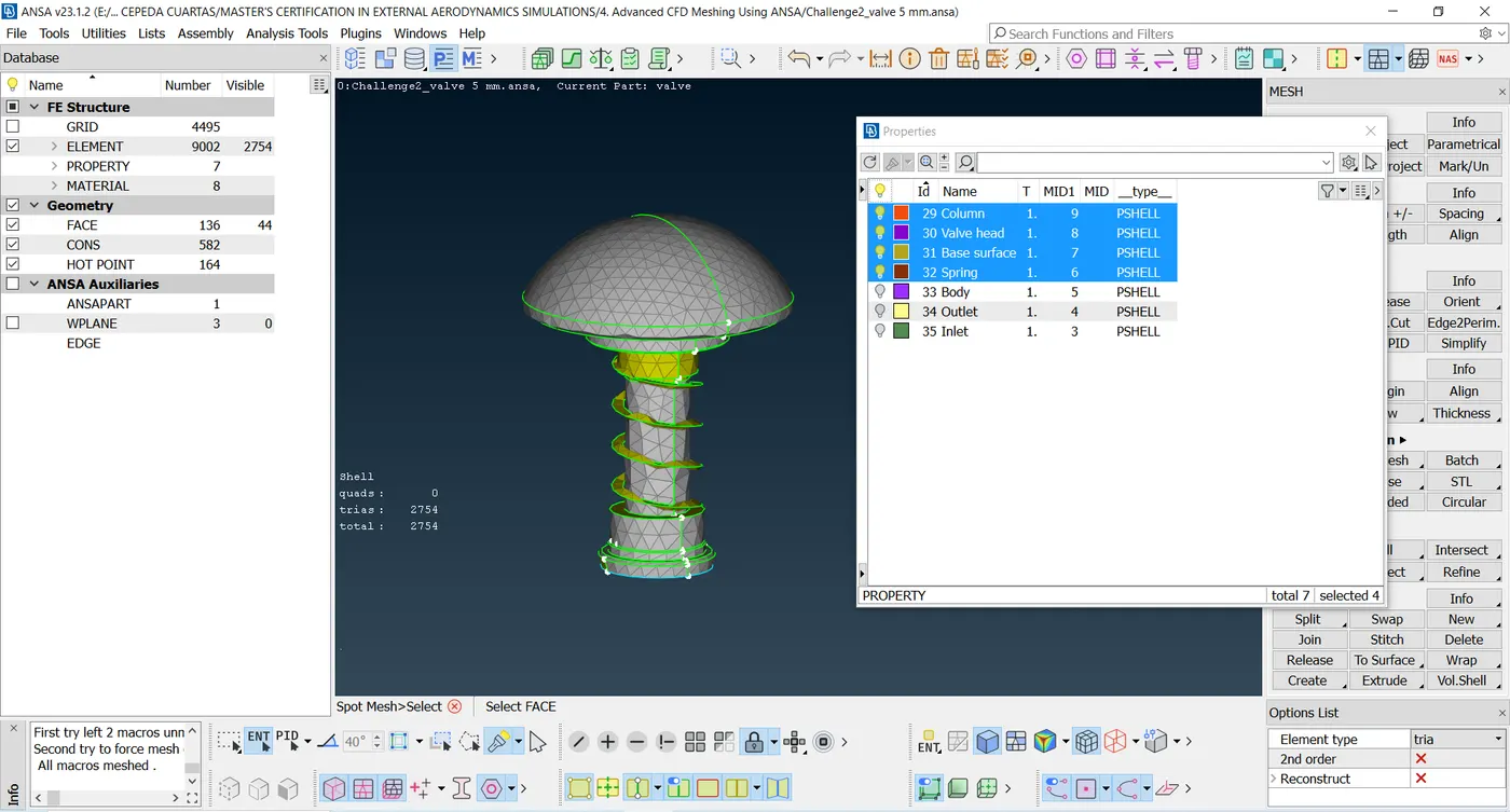
Then, inside the pressure valve are found the valve head, the valve stem, and the stem base surface, as can be seen in the following two pictures.
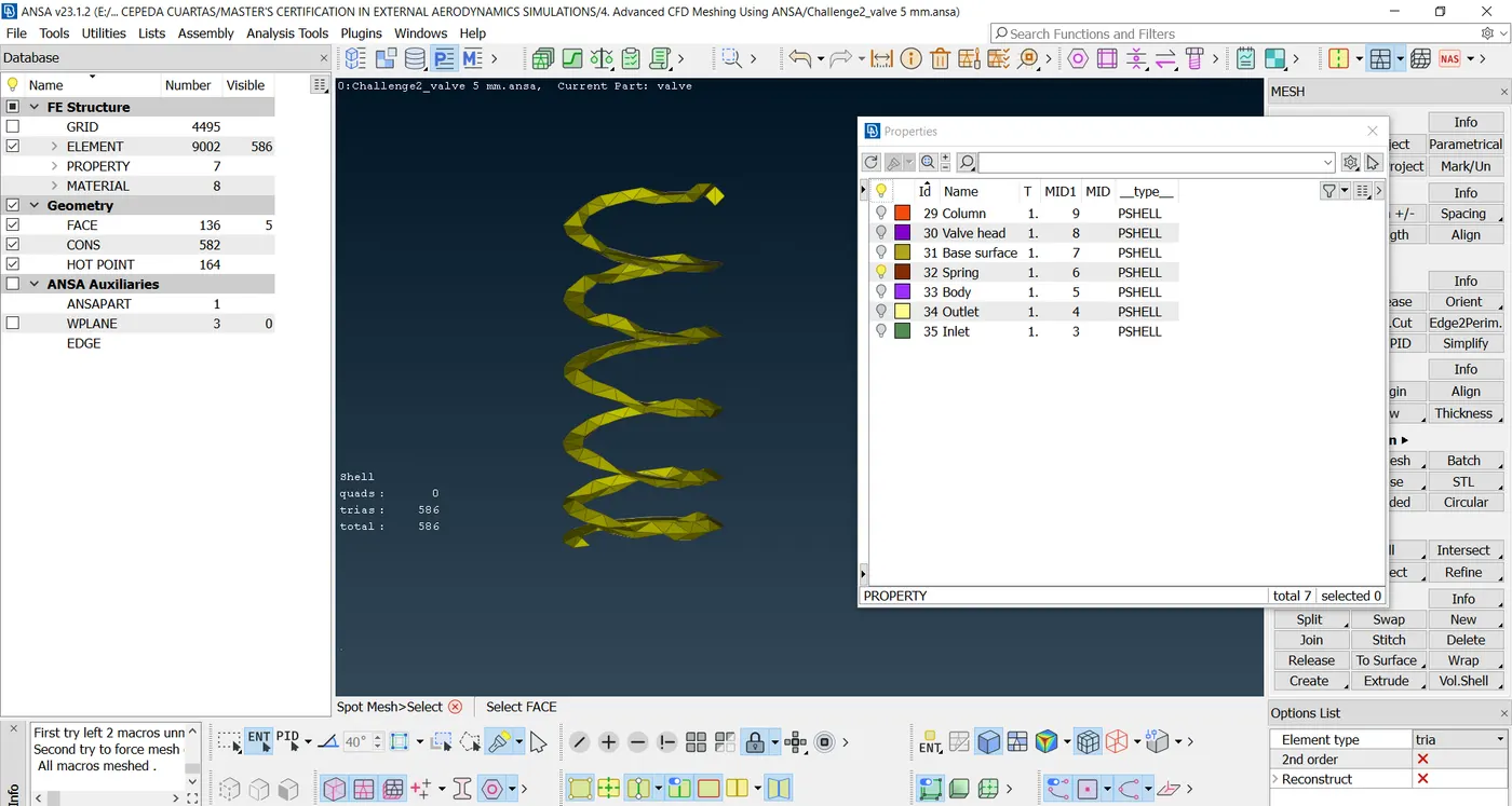
Furthermore, the inner valve body carries a spring along, in the next picture the spring can be seen rolled over the valve stem.
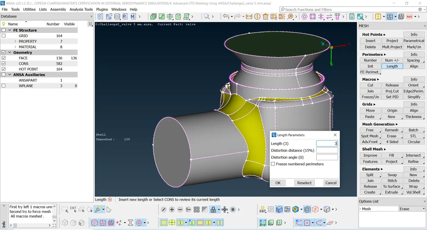
Once the surfaces have been fixed and the valve parts are named, the next step is to generate an initial mesh; to get the mesh, it is used the mesh tool and the length icon that is located on the parameters section from the mesh. As the cell mesh perimeter as the macros section
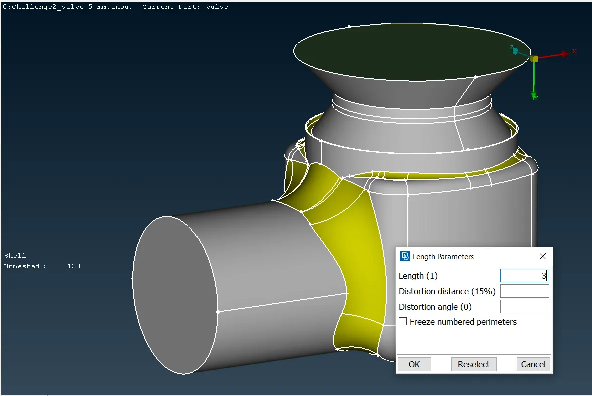
For instance, the mesh size used in the picture below will be equal to three millimeters, as has been set as one of the mesh cases that must be taken, according to the challenge statements.
This project will use four cases, which will be divided as it is shown in the following table.
| Cases | cell-mesh sides sizes |
| I | 1 mm |
| II | 3 mm |
| III | 5 mm |
| IV | Combined |
The mesh size used in the length section must be also used in the Mesh parameters section. Also, the mesh shape selected is triangular.
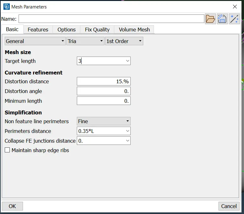
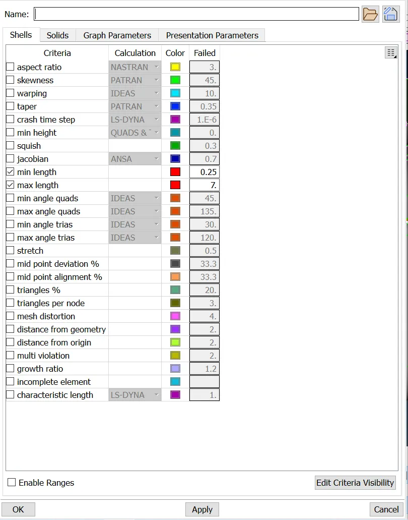
Finally, the mesh sizes will be settled to remain the mesh sizes in a determined range, this range can be set in the Mesh Quality section.
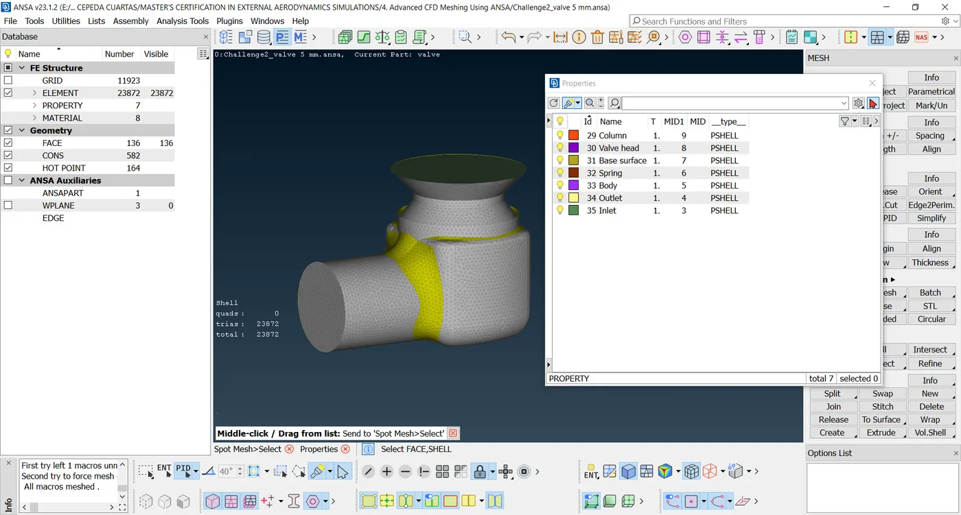
Thus, the final mesh will look like the picture below.
RESULTS
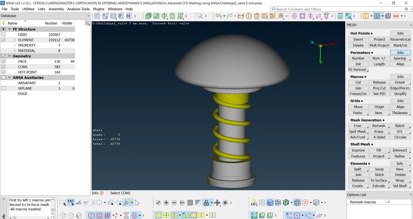
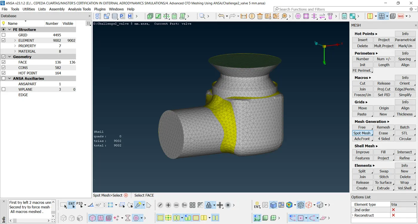
For each case, three different pictures were taken; These pictures are respectively:
- Inner valve body;
- Spring;
- Pressure valve body, inlet, and outlet.
CASE I:
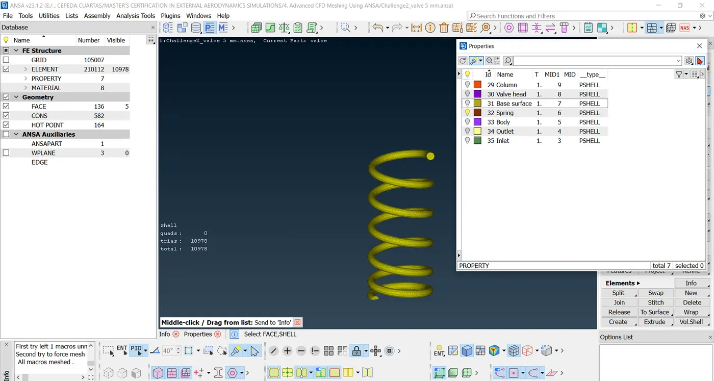
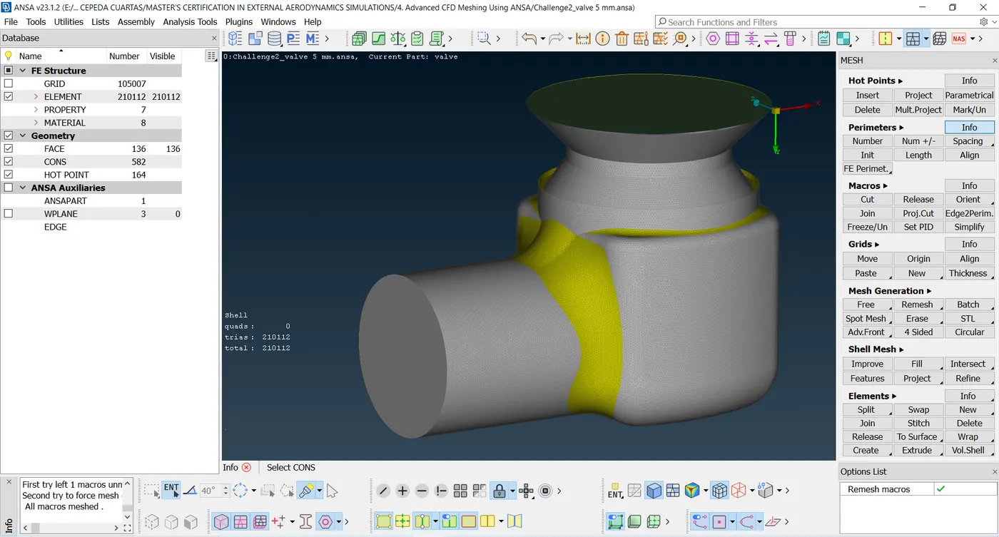
CASE II:
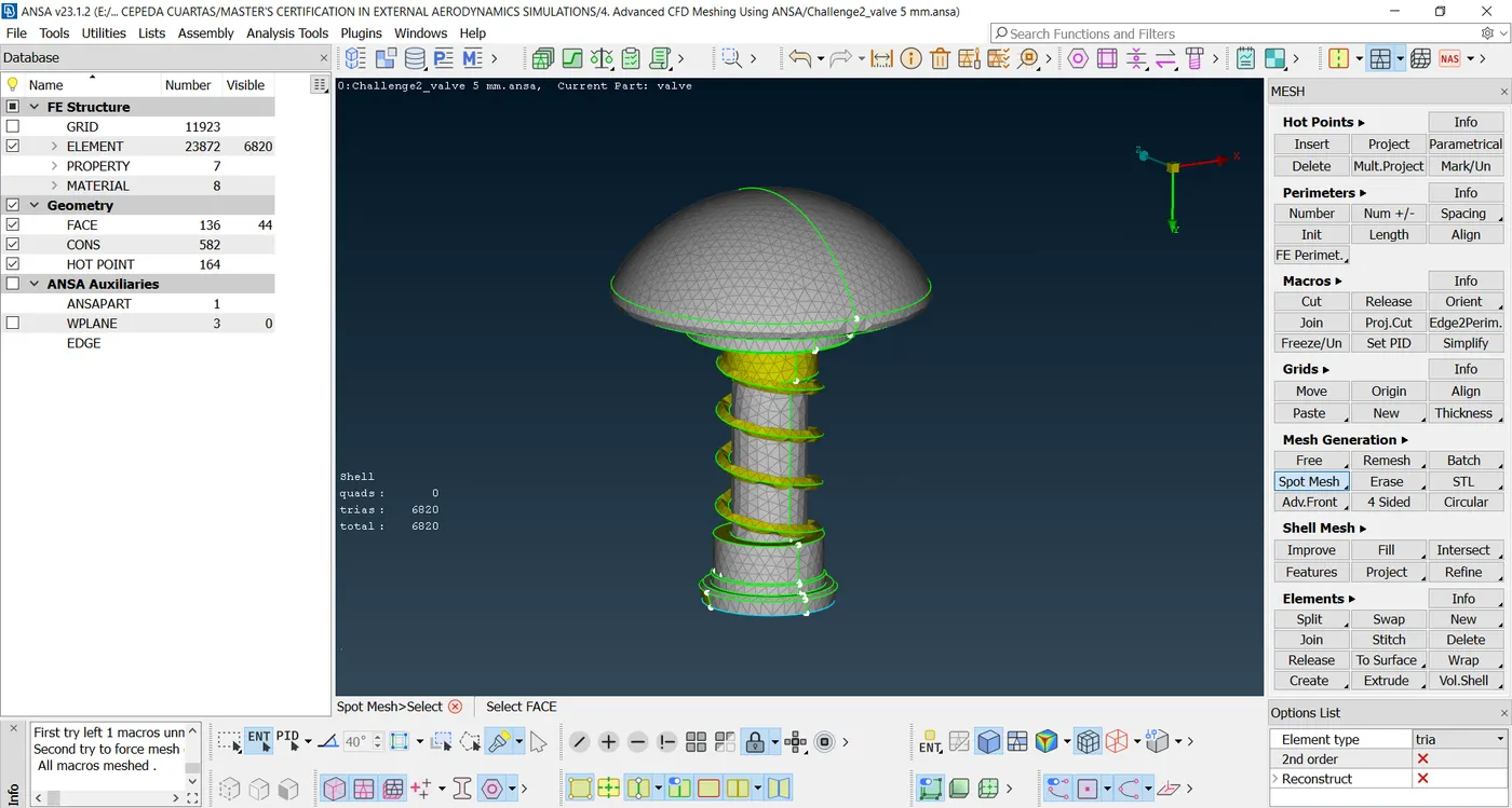
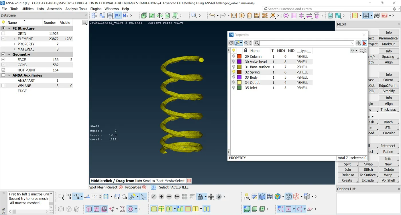
CASE III:
CASE IV:
A. Components with a mesh size of 1 mm
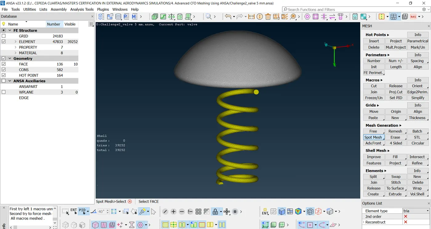
B. Components with a mesh size of 3 mm - including the components shown in the previous image
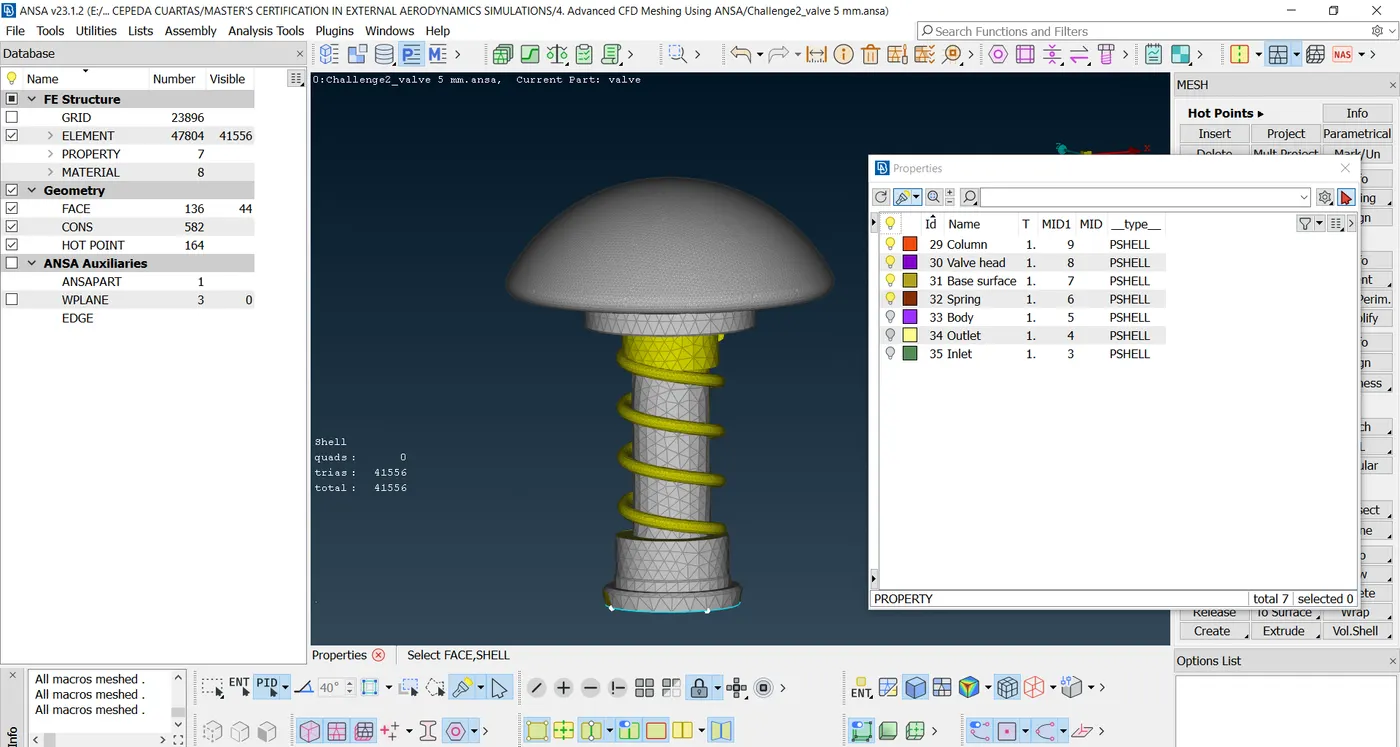
C. Components with a mesh size of 5 mm - including the components shown in the previous image
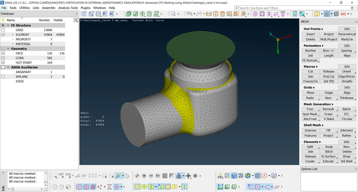
Comparing the spring geometry and the head valve sides geometry obtained in each meshing, it is clear the smoothness of these geometries is getting lost due to the length of the mesh cell; Even the external curves that the pressure valve has, start losing their smoothy shape because of the cell mesh requires to fit into these areas without leaving the range imposed above.
The mesh elements calculated by the program for each case are:
| Case | Total Elements |
| I | 210112 |
| II | 23872 |
| III | 9002 |
| IV | 47804 |
The final case is an advisement case, which the user should carry out in their simulations so that the mesh will be divided into different cell sizes and will keep the mesh domain on the zones where the mesh must get more accurate results. But, if the component needs to get accurate results around its body, it is necessary to use a mesh with cell sizes of approximately one millimeter; however, the running calculation will take too much time to get the results due to the elements' quantity obtained in the first case.
CONCLUSIONS
To get accurate results in determined body parts, the user should use the fourth case shown, avoiding the calculation delay that the mesh weight could cause if this one is too small. Otherwise, if the user is seeking to get accurate results around the whole body, including the inner parts, the mesh size should be low, although the running calculation might trigger a delay in their results.
ANSA is very useful for refining geometries and correcting the surface errors that the component could get in the CAD design programs. It is important to review these geometry errors, before generating the initial mesh either using ANSA topology or using another computational software that can analyze these problems.
Besides the mesh cell size, the cell shape should be taken into account, because mixed mesh could fit better on the component surfaces than triangular mesh.