Week 3 Challenge : CFD meshing on Turbocharger
CFD Meshing of a turbocharger using ANSA
AIM
The following project is about a turbocharger CAD body fixing and meshing, which initially has some surface mistakes and furthermore, it must be meshed around its whole body. It will first fix the double and triple surface mistakes found over the turbocharger body and then use volumetric mesh to mesh the body; it will also use surface mesh if the body sections require it.
OBJECTIVES
Fix the surfaces that have mistakes due to a wrong CAD modeling process by using the surface tools provided by ANSA software.
Apply volumetric and surface meshes if it is required, to get a smooth mesh over the turbocharger body.
Assign different mesh cell sizes to each turbocharger part and determine the body smoothness once the mesh is set.
ENGINEERING DEVELOPMENT
Firstly, using the topography tools provided by ANSA, which also were used in previous projects (Project link found in References part), the turbocharger body surfaces are fixed and refined to get a smooth body that does not generate any issues in the body meshing. Then, the turbocharger fixed body has the following parts:
A. Outer casing: which covers the blades and shaft parts; also, allows addressing the flow.
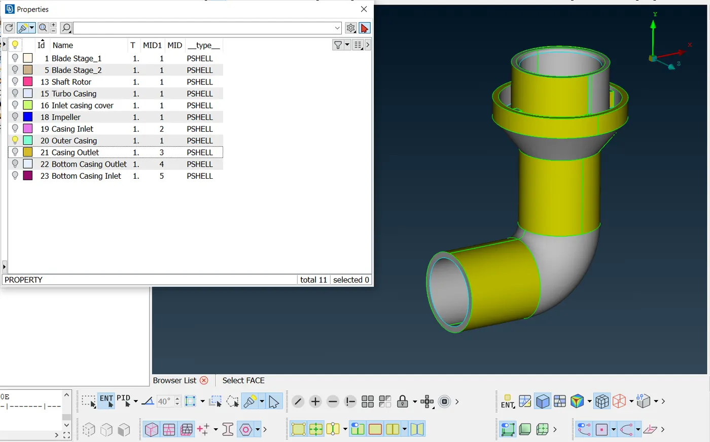
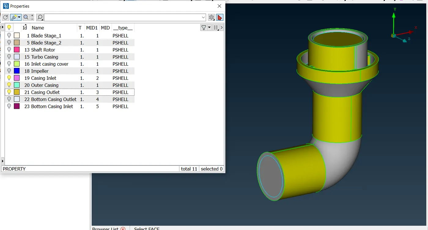
B. Inlet & outlet surface: These ones are created to simulate the inlet and the outlet sections where the flow will respectively be moved. The inlet surface is the top surface located over the cross-section body (Plane XZ), and the outlet surface is the bottom surface also located into the cross-section body (Plane YZ).
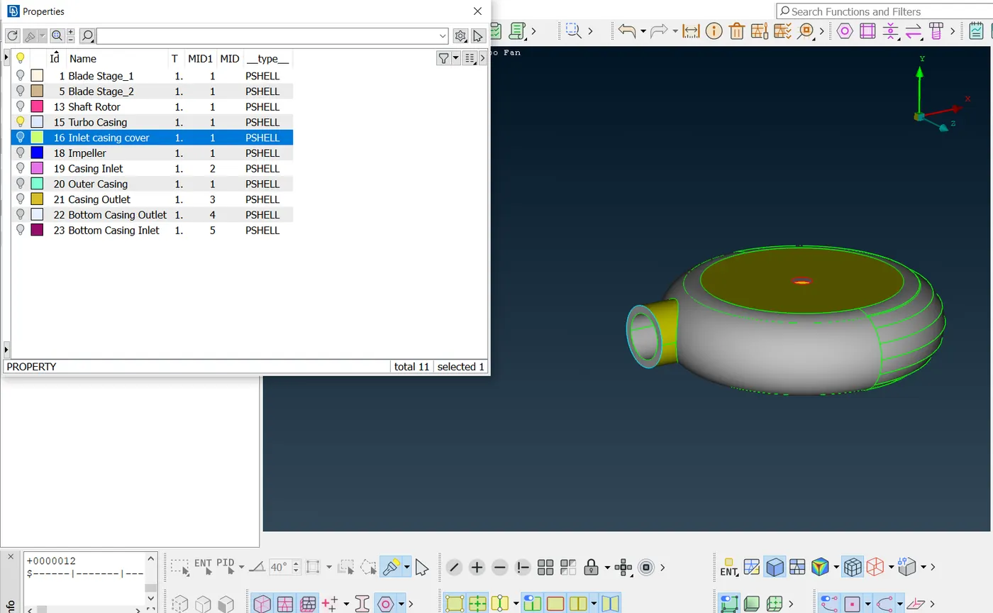
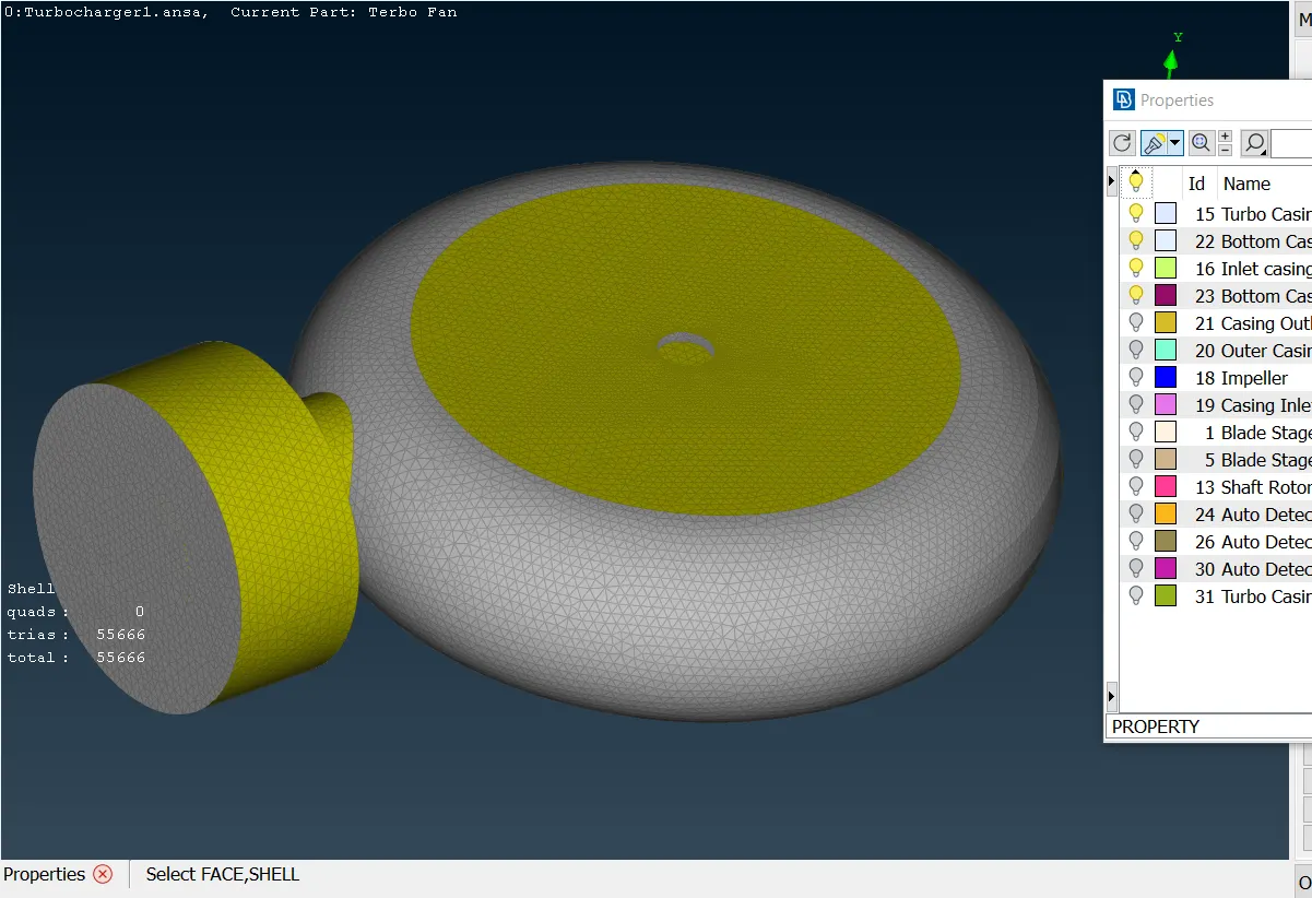
C. Turbocasing: The turbo casing is the external body shown in the picture below, whose main function is to cover the impeller and protect it; furthermore, its curved shape allows the flow does not to generate cavities into the free space.
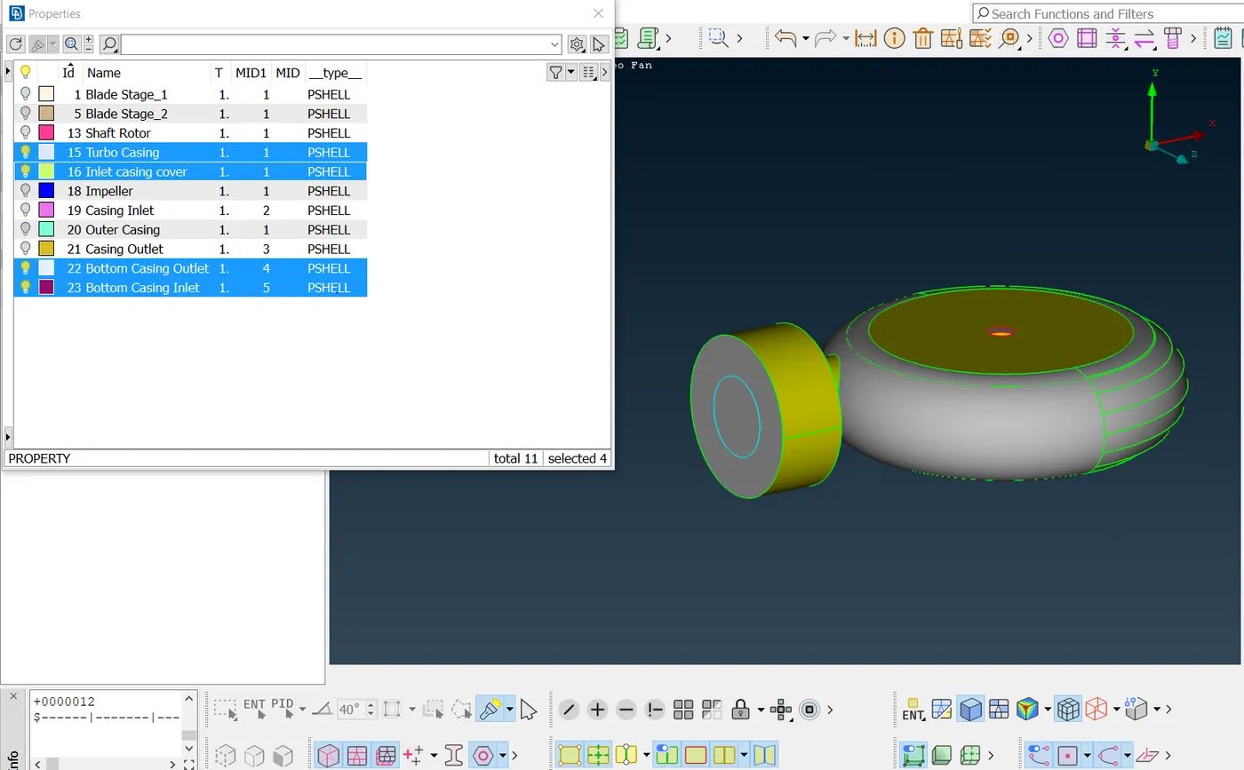
D. Inlet casing cover: The inlet casing cover is just a structural section at the entrance from the turbo casing, whereby the flow will enter into the turbo casing body. The outlet section is located under the turbo casing body.
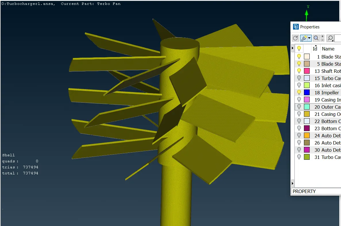
E. Blade stages and shaft: The blade stages will make the flow gain impulse inside the free space from the casing body; Likewise, the blades will swirl because the shaft generates enough energy to turn over the Y axis.
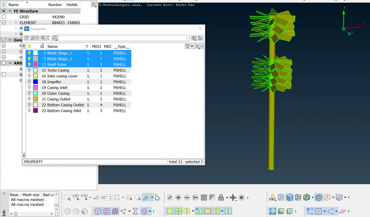
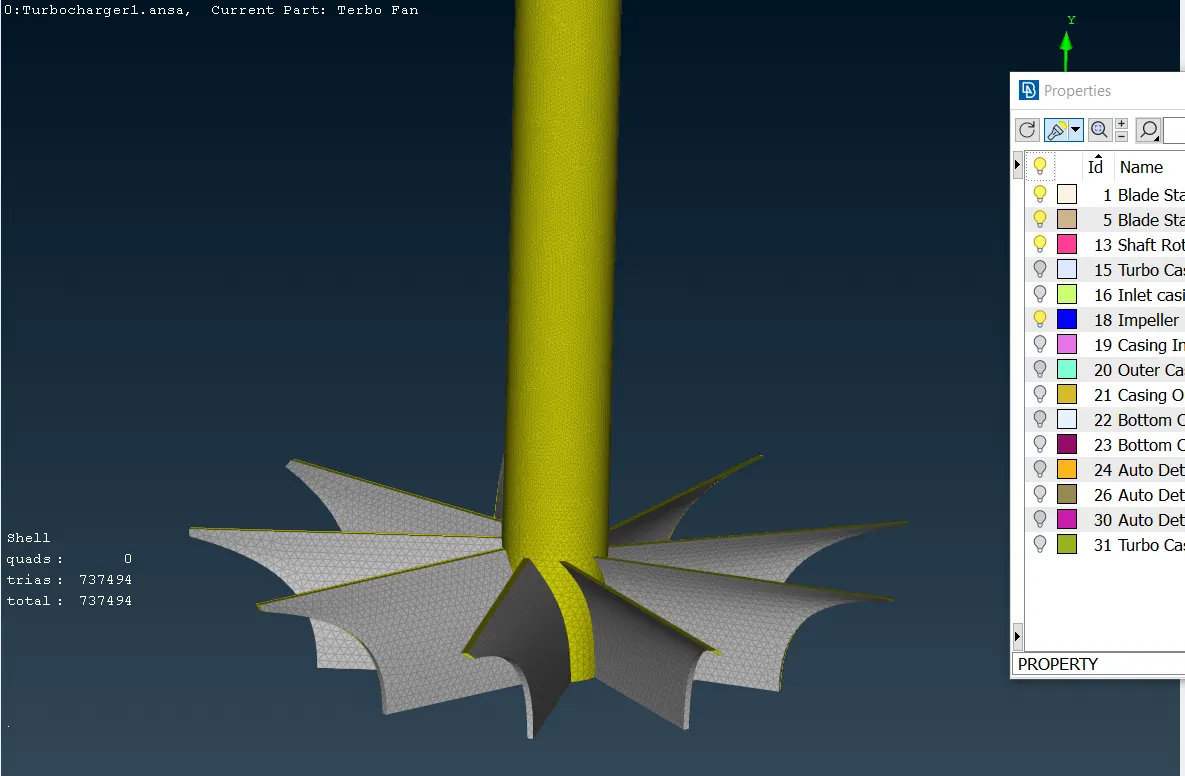
F. Impeller: The impeller is located inside the turbo casing body and this one also impulses the flow.
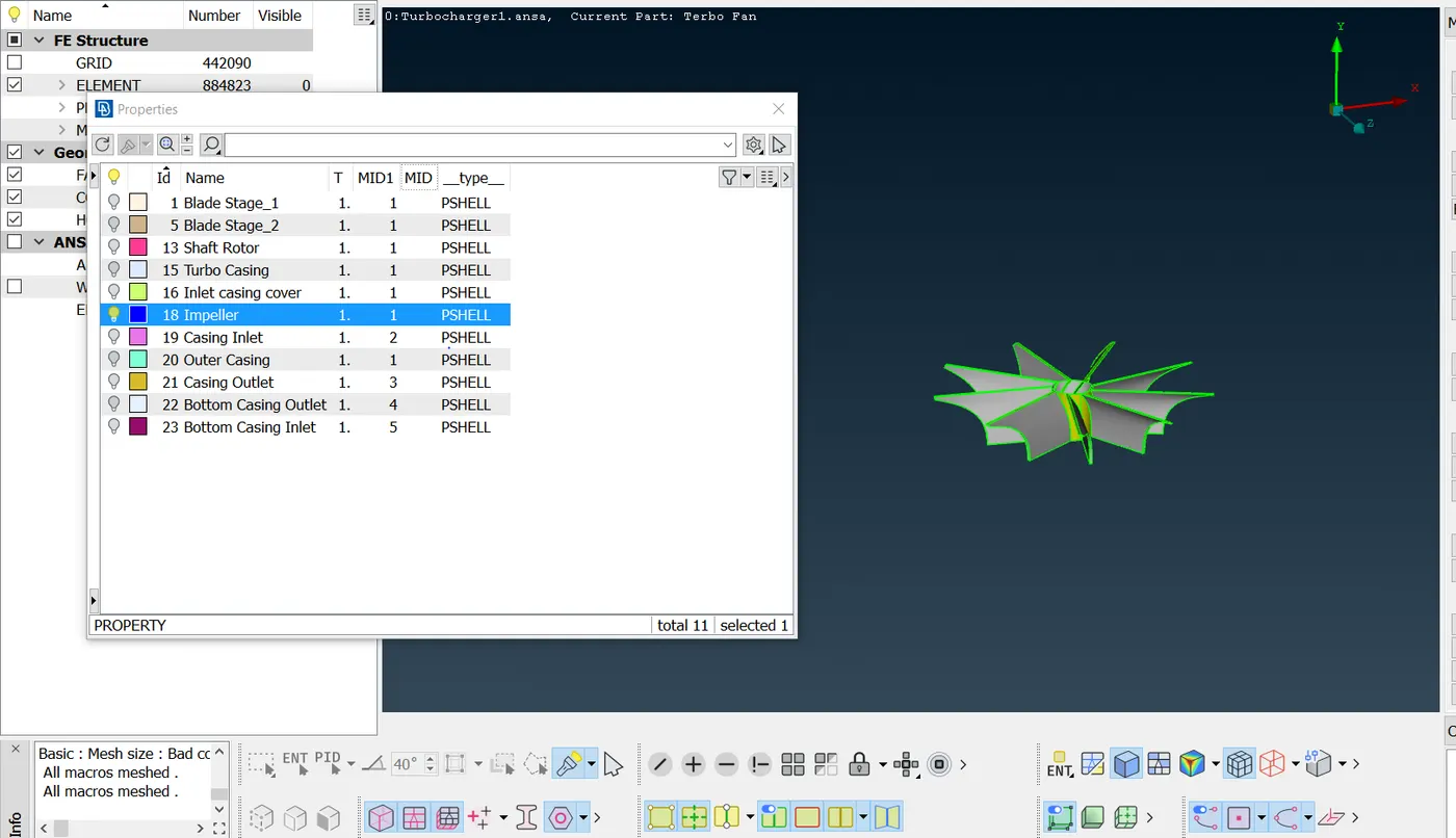
Knowing each body part and its function, the next step is to put the mesh over the bodies, taking into account the mesh-cell sizes that were provided by the challenge statements. The following table is about the mesh-cell size that each part will have and also, the parametric mesh-cell sizes that will be allowed, depending on the mesh-cell size imposed.
| size of mesh-cell side (mm) | Minimum length (mm) | Maximum length (mm) | |
| Blade stage 1 | 1 | 0.5 | 2 |
| Blade stage 2 | 1 | 0.5 | 2 |
| Impeller | 2 | 1 | 3 |
| Shaft rotor | 1 | 0.5 | 3 |
| Turbo casing | 5 | 3 | 7 |
| Compressor casing | 5 | 1 | 7 |
| Inlet casing cover | 5 | 3 | 7 |
Thus, the values shown in the table are set in the mesh features and mesh parameters as it can be seen in the following two pictures.
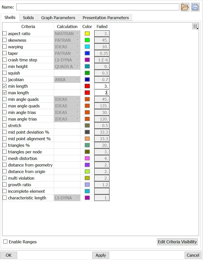
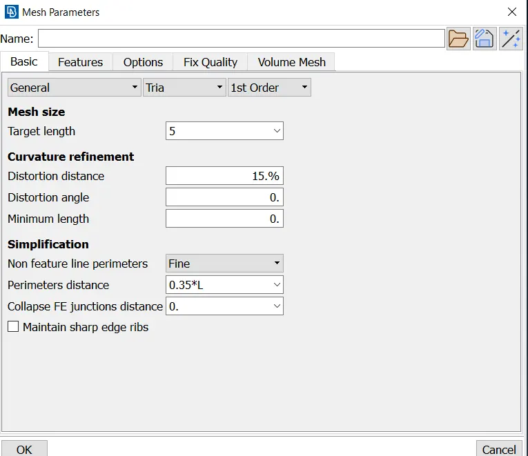
The perimeter and macro length are found in the length section, located in the Perimeters icon from Classic mesh section. In these sections, the average mesh-cell size value must be set so that the program will include the determined measure over each cell from the part selected.
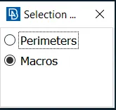
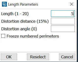
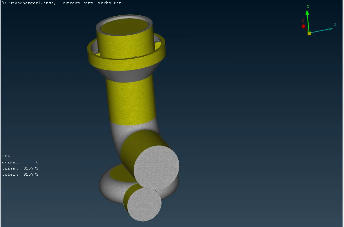
Finally, the meshing over each part surface will look like as it is shown in the image below.
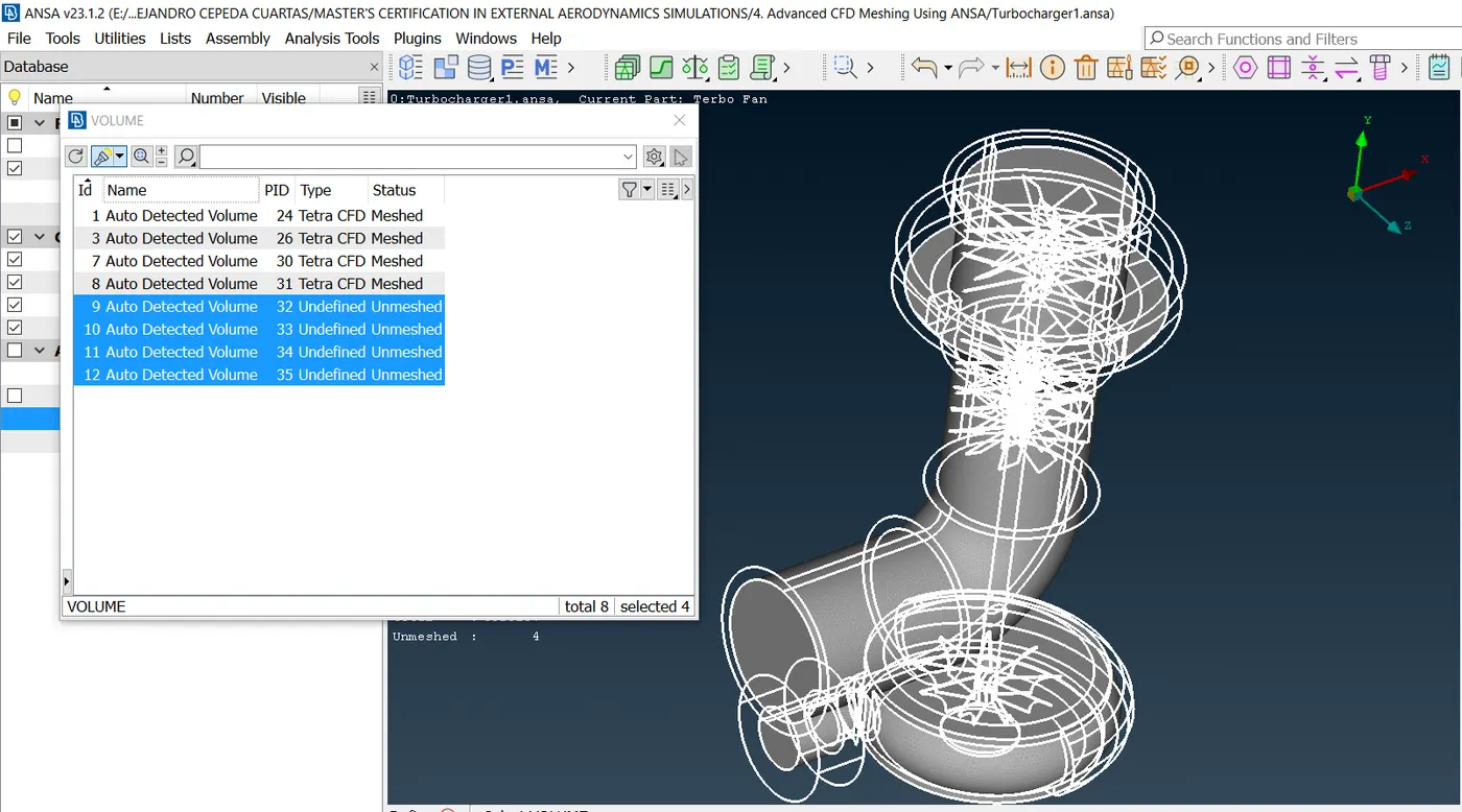
Once the surface meshing is done, it is now necessary to get the body and the meshing in the free space sections; these new bodies will play as a flowing mass that will pass through the body. Using the Volume tool, the flow volumes and their meshes can be easily created. So, once this tool is used, the bodies and their respective cavities will be considered by the program to generate the volumetric meshes. The image below shows the surface bodies and the new cavity bodies, however, the surface bodies have already been meshed and do not have any thickness for generating a volumetric mesh over them.
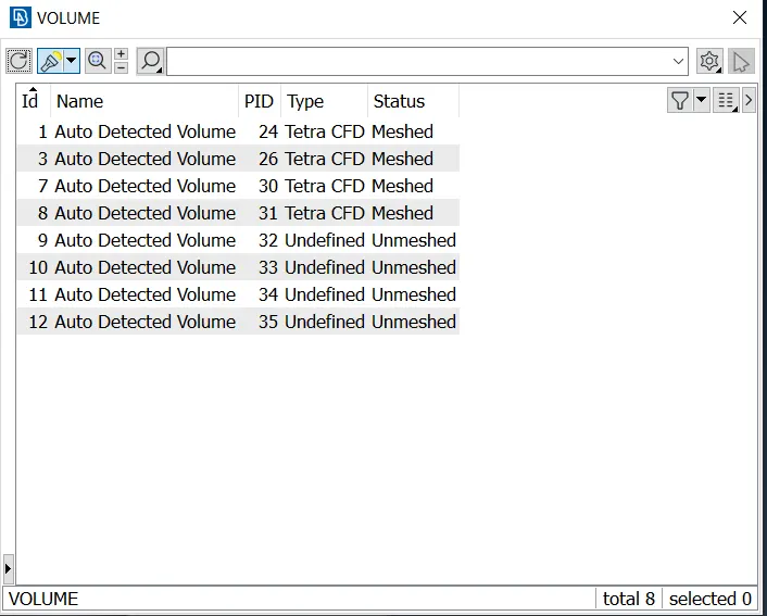
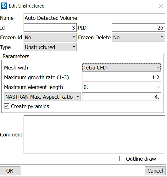
The surface bodies then must be deleted from the Volume toolbox and the new body cavities must be refined in order to generate a CFD volumetric mesh over them. To do that, it is only clicked twice on each body cavity; then, the type of mesh is selected, being Tetra CFD mesh in all these cases.
The following picture shows the bodies previously meshed, which must be deleted.
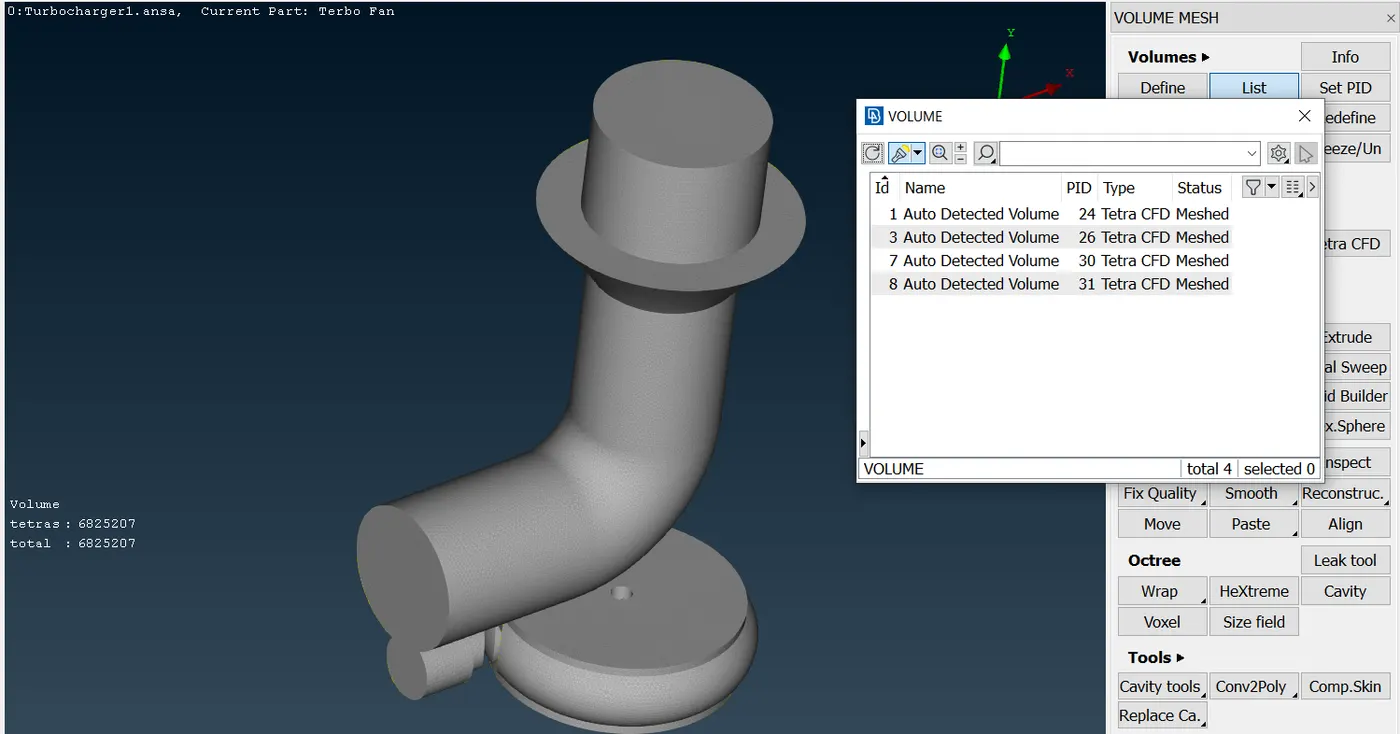
Finally, the volumetric meshes were obtained by using the Volume tool, and look like the following picture.
RESULTS
The surface bodies for each case look like the following pictures:
- Surface mesh
A. Casing - Inlet - Outlet
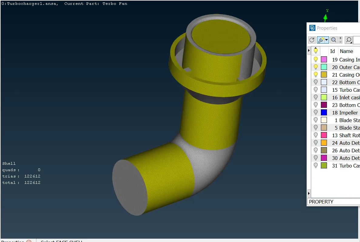
B. Turbocasing - Inlet casing cover - Inlet - Outlet
C. Blade stages - Shaft
D. Impeller
The mesh elements obtained for each section are:
| Turbocharger body parts | Mesh elements |
| Casing | 122612 |
| Turbo casing | 55666 |
| Shaft | 76865 |
| Blade stages | 640290 |
| Impeller | 20339 |
- Likewise, the volumetric meshes for simulating the flowing mass look like the following pictures:
- Volumetric mesh
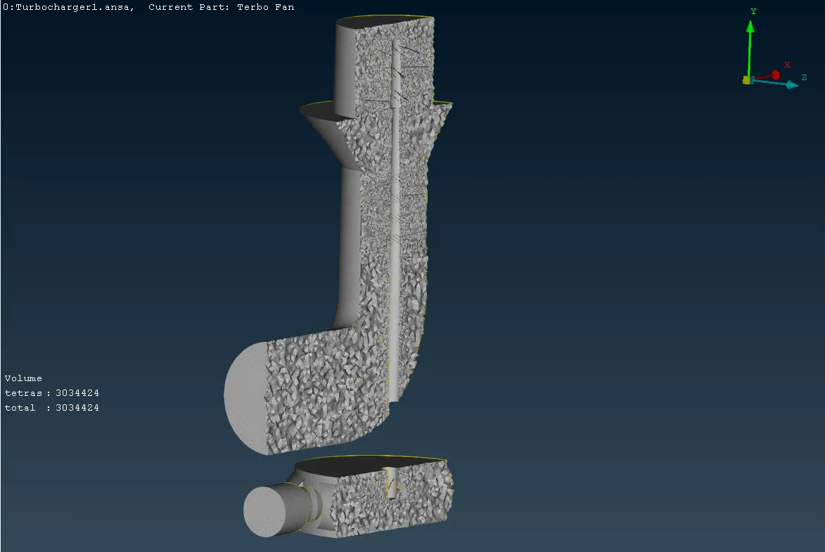
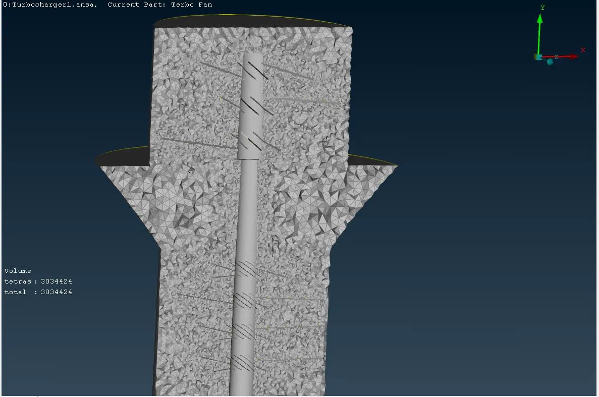
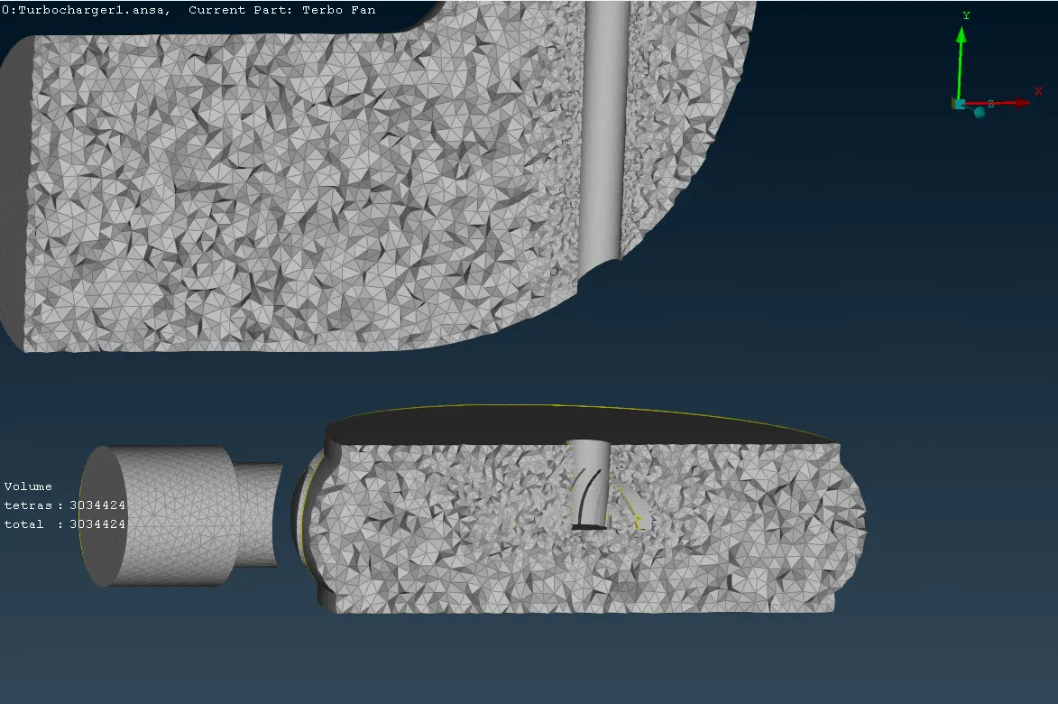
It can be seen in the pictures, that the cavities got the shape of free spaces, even the blade shape into the casing bodies. Thus, the blade will fit accordingly inside the volumetric meshes as it is shown in the following picture.
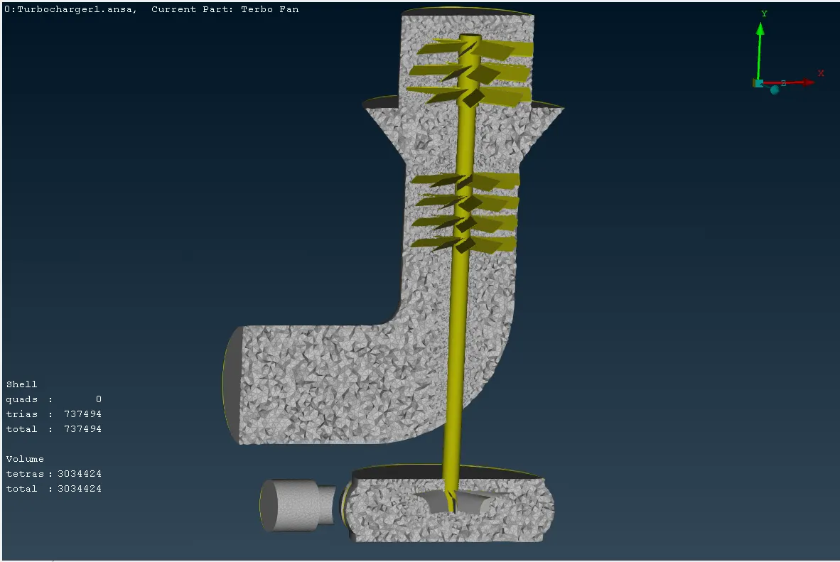
In the same way, the final mesh elements result as surface mesh elements as volumetric mesh elements are equal to:
| Surface mesh elements | Volumetric mesh elements | |
| Turbocharger body | 6825207 | 915772 |
CONCLUSIONS
ANSA program does not need the use of geometric tools to get the fluid body, in comparison with the ANSYS tools. However, the capacity of some computers cannot generate the mesh required, because of the elements generated in the meshing process can generate delays in the computer performance, even triggering computer lacks. It is advised to hide the components meshed once the program has achieved the correct mesh over them.
REFERENCES
https://skill-lync.com/student-projects/week-2-challenge-surface-meshing-on-a-pressure-valve-451