Week 3 - External flow simulation over an Ahmed body.
Ahmed Body Project
AIM
The following project is about the Ahmed body simulation once this body is moved into a flow field. It will be firstly explianed how the ahmed body is going to be adapted at the ANSYS software, using different methods to generate thigs such as the control volume which the body will be contained, the mesh refinement as around as close to the Ahmed body, the main parameters that they will be used to get an accurate simulation and the type of solution method, taking into account the flow over this body is turbulent. Then, it will be determined the flow behavior and the results obtained varying the mesh grid sizes, showing the simulation result plots and giving the coefficient values obtained in each variation case. Furthermore, the parameteres as velocity and pressure will be shown in contour plots, in order to analyze a non-typical physical behavior that it is normally obtained in simulations where the flow behavior tends to be turbulent.
EQUATIONS
Y plus:
`y=(vartheta*y^+)/(u_t)`
where:
`u_t=`Frictional velocity
`vartheta=`Kinematic viscosity
`y^+=`Dimensionless wall distance
Frictional velocity:
`u_t=sqrt(tau_w/rho)`
where:
`tau_w=`Wall shear stress
`rho=`Flow density
Wall shear stress:
`tau_w=1/2c_f*rho*V^2`
where:
`c_f=`friction coefficient
`V=`Free stream velocity
Friction coefficient:
`c_f=0.0576*(Re_d)^(-1/5)`
where:
`Re=`Reynolds number
Dimensionless velocity:
`U^+=V/u_t`
OBJECTIVES
Refine and simulate the flow behavior over an Ahmed body provided by the project parameters.
Determine the flow behavior characteristics in comparison with some Ahmed body paper researches carried out.
Explain the importance of the Ahmed body in CFD simulations.
ENGINEERING DEVELOPMENT
Ahmed body: The "Ahmed body" is a conceptual model of a car body which was designed to simulate and improve the modern cars unstability and performance, because of the common car shapes get a high drag that is triggered in much cases by the squared shape that the car has. Many car designer companies takes the Ahmed body as an initial model to develop the shape variation in order to obtain a car model which will have determined features that they will improve the car design performance.
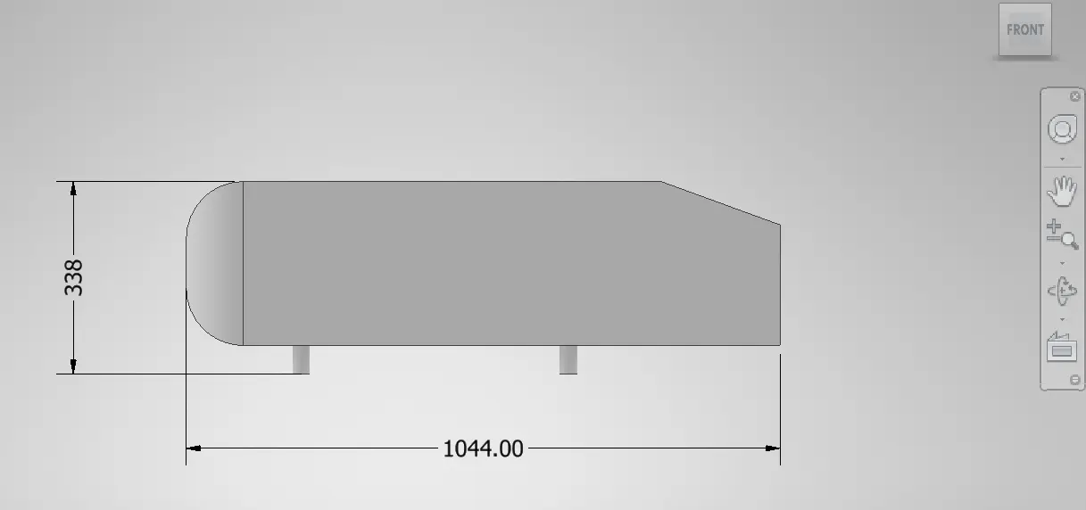
Ahmed body is provided by the challenge resources, so, according to this 3D model, Ahmed body has the following measures:
- Right-side view
- Front view
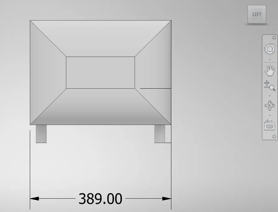
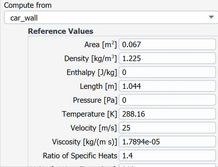
The characteristic length in this case will consist in the length measure that the CAD has, taking into account that the flow will move fron the front side to the back side; then, the characteristic length value will serve for calculating the Reynolds number and also, the wall distance heigth which is necessary to get accurate drag and lift values. The velocity will be equal to `25 m/s`and the flow parameters will be the same as the normal air conditions, where density is 1.225 `(Kg)/(m^3)`, dynamic viscosity is `1.789*10^-5 (Kg)/(m*s)` and, kinematic viscosity is `1.48*10^-5`; thus, Reynolds number, friction coefficient,wall shear stress and `u_t` number will respectively be:
`Re=1'787.171,6`
`c_f=0.0032359`
`tau_w=1.23873 Pa`
`u_t=1.01 m/s`
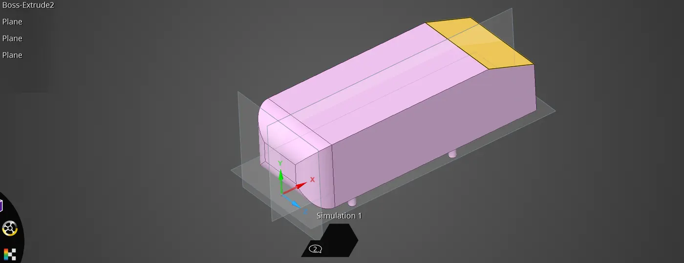
The `y^+` value can be taken, assuming it as 150 (value taken from:https://www.simscale.com/docs/validation-cases/aerodynamics-flow-around-the-ahmed-body/), then, the wall distance heigth should be equal to `y=0.002198 m`. Now the simulation can be performed. The Ahmed body looks like:
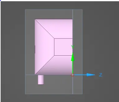
Because of the Ahmed body used for the CFD simulation is symmetric along the Z axis, this one can be splitted at its half section and one of its halves can be deleted. In the next picture using split body function provided by ANSYS Discovery, the Ahmed body is splitted over its half.
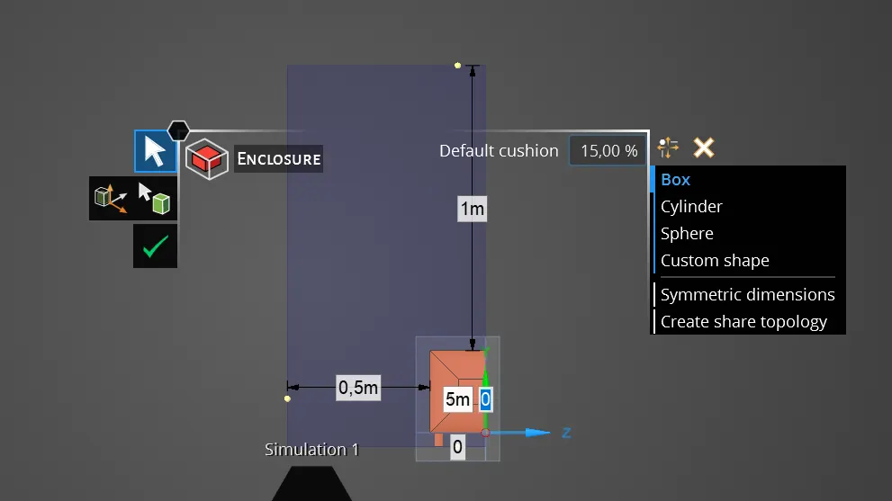
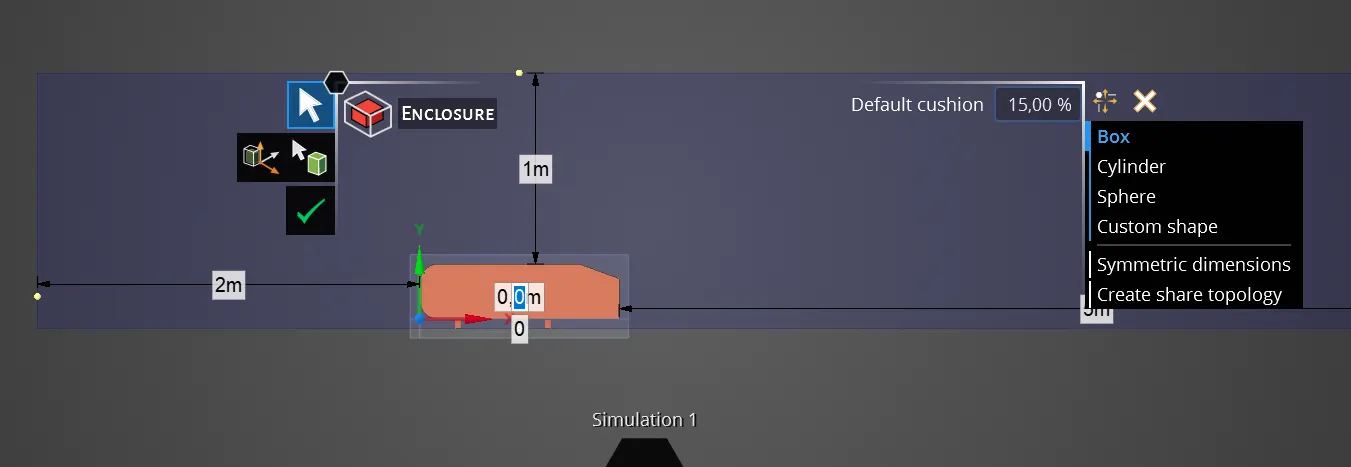
Other funtion knowing as "Enclosure" is used in this secction in order to prepare the 3D body, due to the simulation will be carried out in a 3D control volume model. The "enclosure" function contains the ahmed body around its six faces by means of a prism which their sides can be detached from the Ahmed body faces, so that the space between those detached faces will serve for adding the mesh volume divisions. The control volume prism will have the following measures from the Ahmed body:
- Ahmed body front view:
- Ahmed body right-side view:
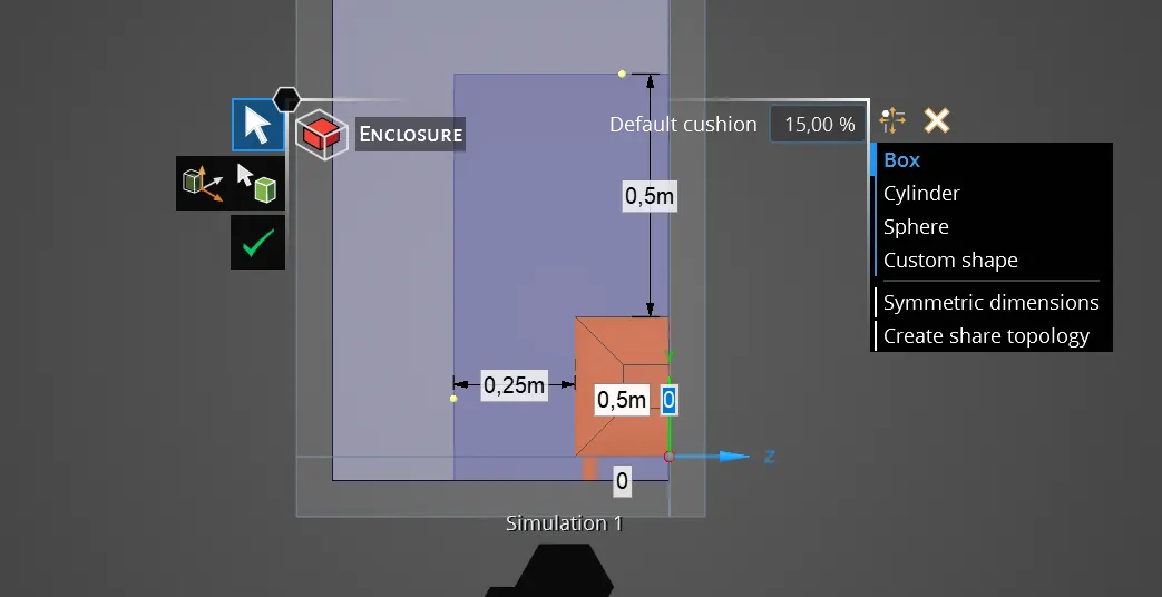
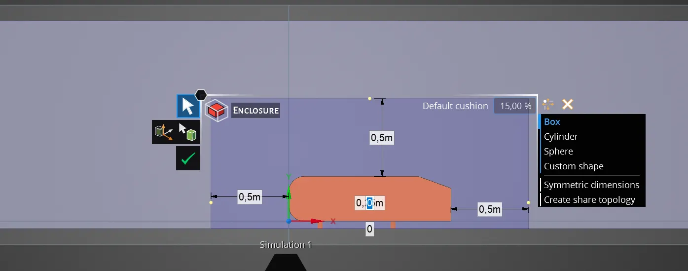
Likewise, a second control volume cube is added into the main control volume prism, to refine in a better way the mesh that will be close to the ahmed body; this mesh is performed because of the software license restrictions do not allow the body has an infinitesimal mesh division, being required some methods to guarantee the simulation accuracy without overpass the license restrictions. Thus, the main body attached above will be divided in a high mesh volumes and the inner body will be divided in smaller mesh volumes.
The main Ahmed body edited is finally supressed from the simulation and the enclosure bodies obtained are used for carrying out the body simulation instead. The final geometry will be:
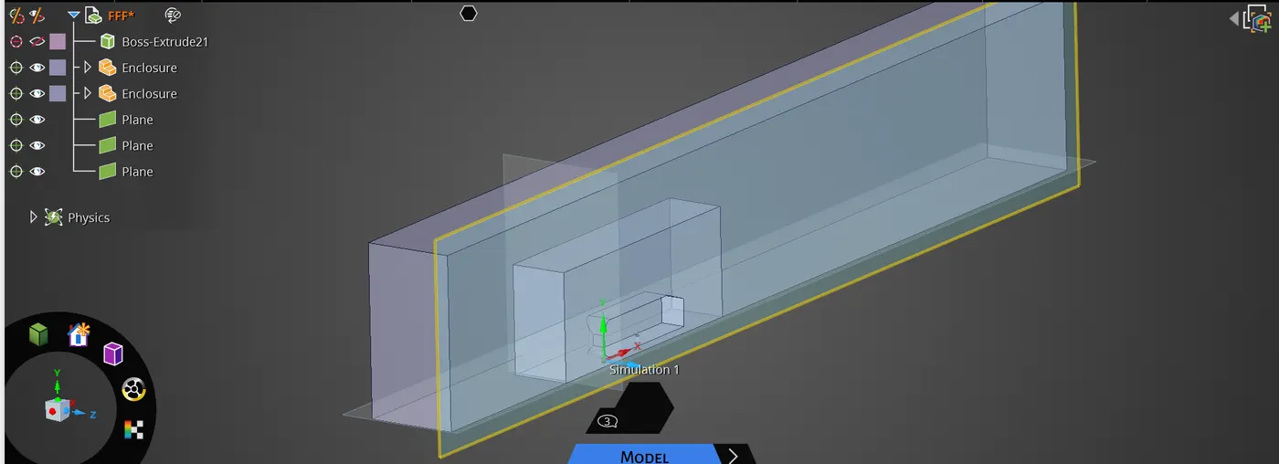
Simulation geometry is taken to the meshing section, where will be applied the meshing methods to get a mesh that will ensure the results obtained in the flow simulation will be as accurate as possible. In this section there will be two bodies which are the ones who were created above.
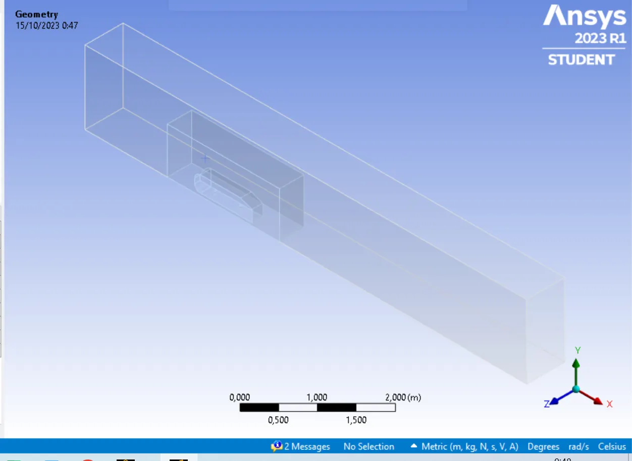
The mesh is generated and then, using the methods explained in previous projects, the mesh of the main body is tidied and divided approximately in volumes with the same sizes, as it is shown in the following picture.
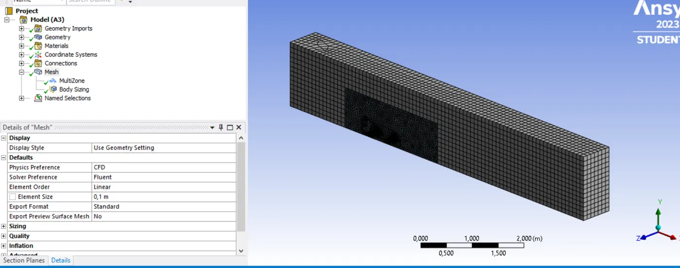
As the same way, the inner boddy is also refined, however, the mesh volume sizes will be smaller than the main body.
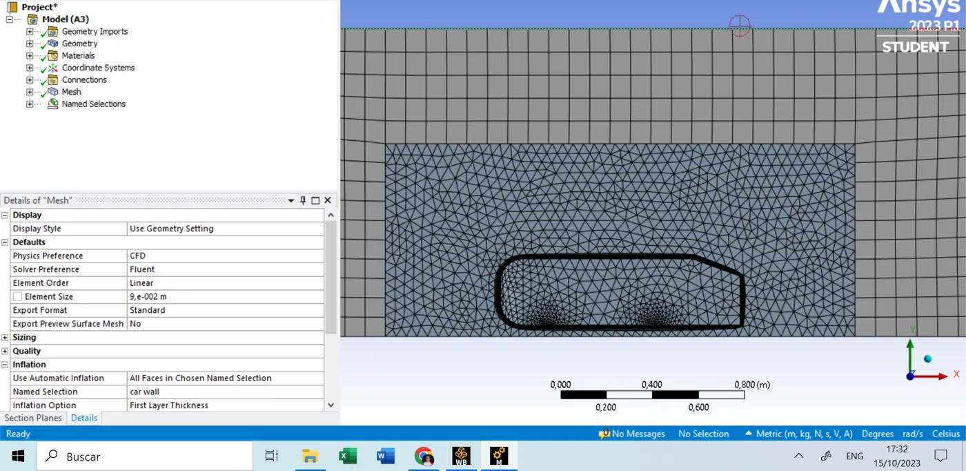
Finally, using the inflation mesh tool, and taking into account the wall distance heigth obtained above is equal to 2.198 mm, it is defined the mesh volumen division around the entire Ahmed body, so that the turbulence model will be performed in an accurate way over the car walls.
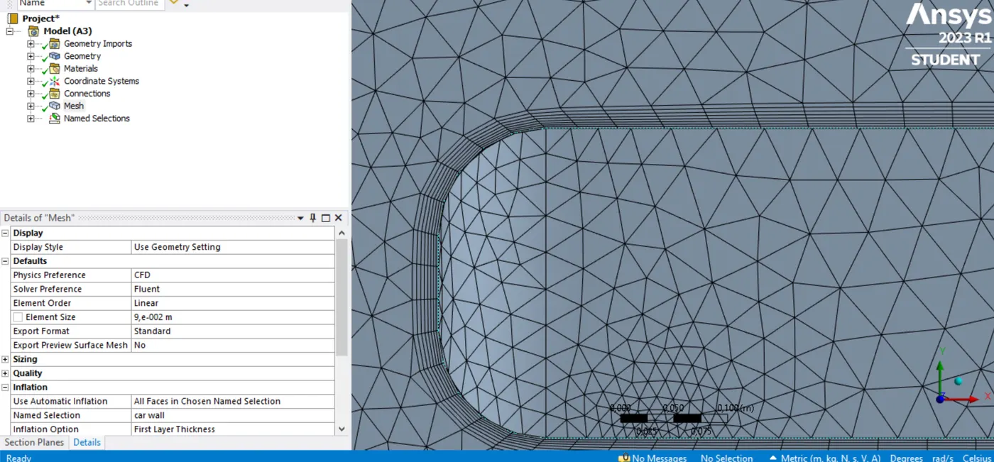
Now, the mesh measures will be varied to determine what it happens with the simulation results in every mesh variation. The mesh will have the following features:
- Mesh independency test
| Case I | Case II | Case III | |
| External body | 11 mm | 9 mm | 7mm |
| Internal body | 5.5 mm | 4.5mm | 3.5mm |
| Car body surfaces | 2.198mm | 2.198mm | 2.198mm |
| Growing scale factor | 1.2 | 1.2 | 1.2 |
| Number of nodes | 30217 | 40386 | 68762 |
| Number of elements | 79988 | 112578 | 198474 |
As it can be seen on the table, as the growing scale factor as the car body surfaces mesh will not vary because of the wall distance height should be constant, due to the simulation parameters will neither vary. The number of layers taken for covering the body surfaces is 8.
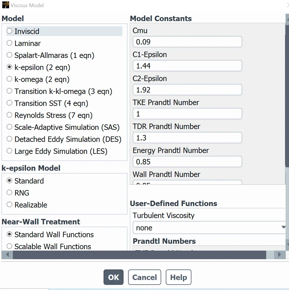
Now, to define the simulation parameters, it is used ANSYS Fluent, where it will be firstly set the main model that the simulation will take in order to reach a correct convergency with an accurate results. Reynolds number calculated is greater than 2200, that means the model it has to be used is a turbulent model; K-epsilon will be used in this particular case to analyze the flow behavior around the body.
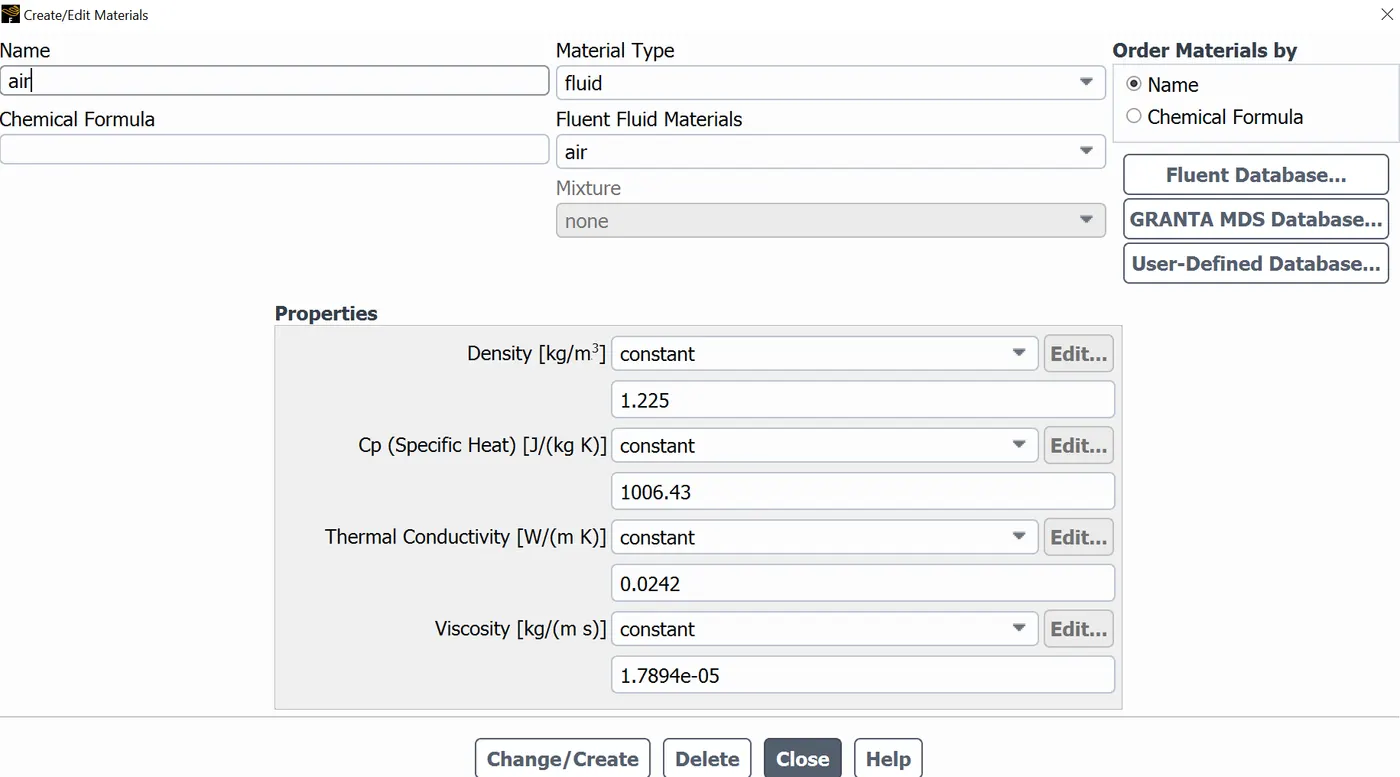
The flow will be air at standard conditions, accomplishing the calculus performed above, to calculate the wall distance height.
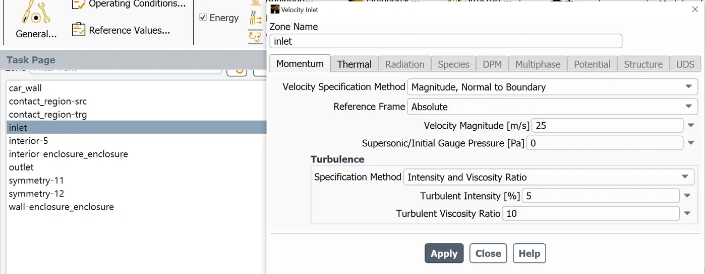
Likewise, the velocity is set at the inlet section, taking the front view from the model as a flow inlet.
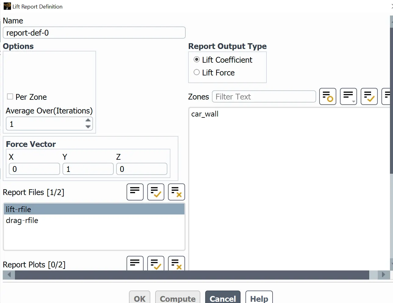
Then, to determine the results behavior regarding the grid variation is generated a file report of drag and lift coefficients. The following picture shows the report files creation.
The values computed above will be used in the simulation reference values, however, the area in this section represents the Ahmed body cross section area divided over two; this area value is taken due to the Ahmed body was previously splitted. Take into account the value is obtained by taking the bigger body and the body supports cross section.
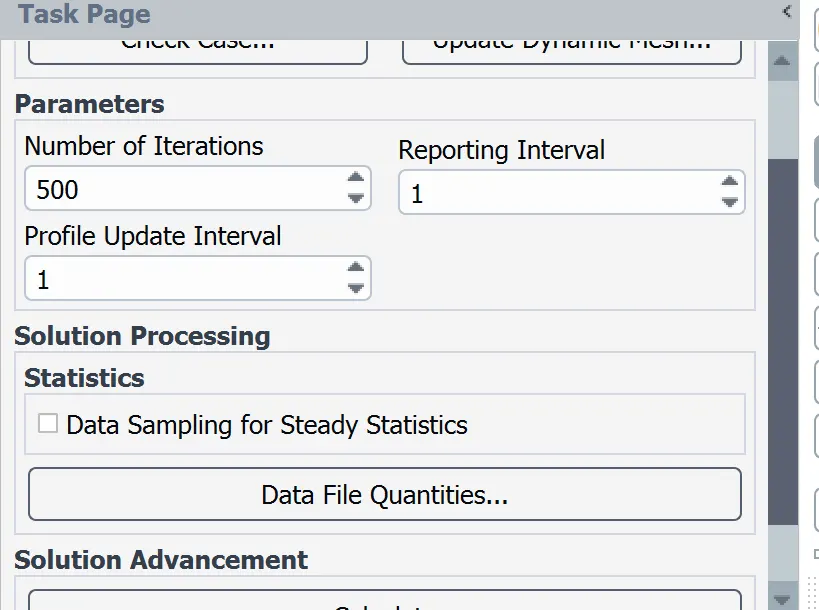
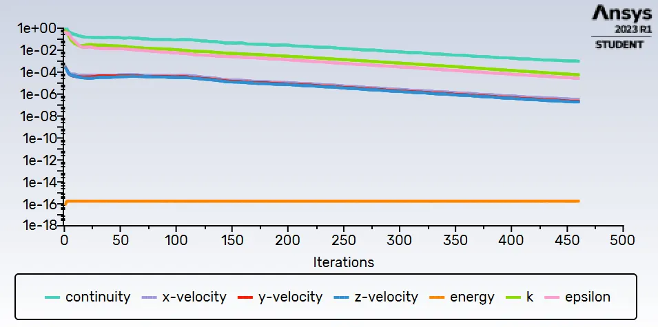
Finally, the simulation will be carried out using 500 iterations at steady conditions. The iterations number will be the same in the all three cases.
RESULTS
The results obtained in each case is:
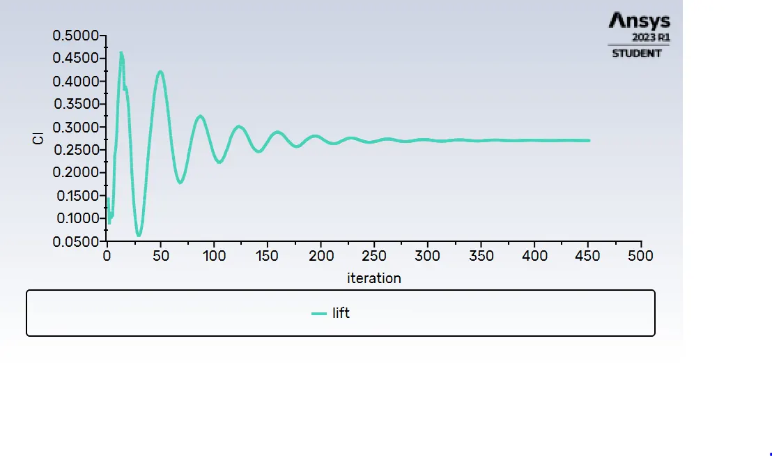
Case I
- Lift coefficient:
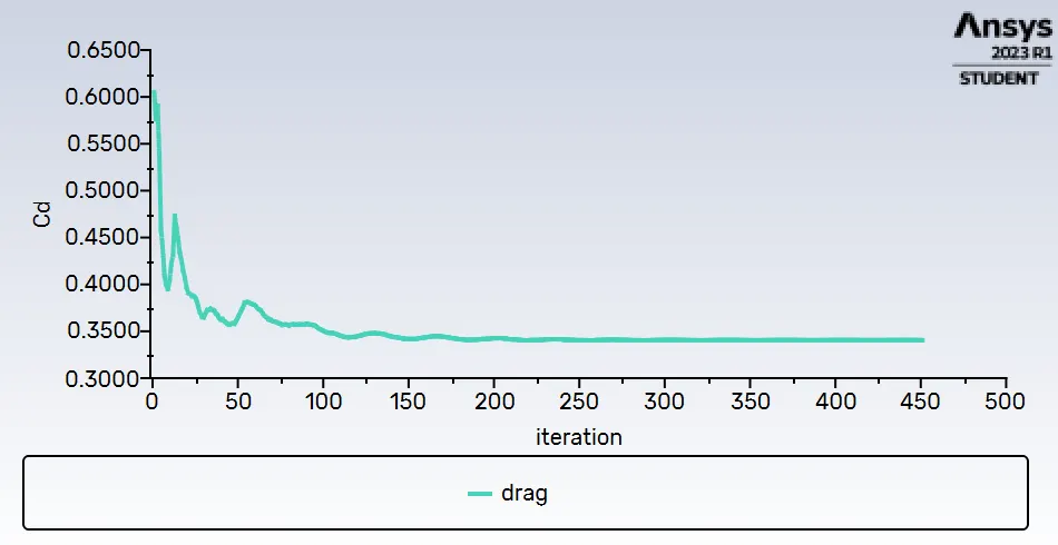
- Drag coefficient:
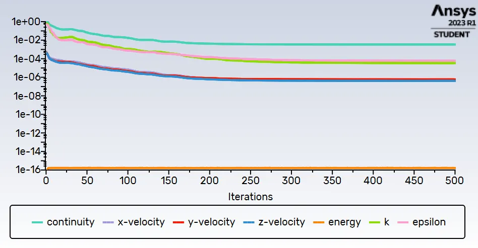
- Convergency:
Case II
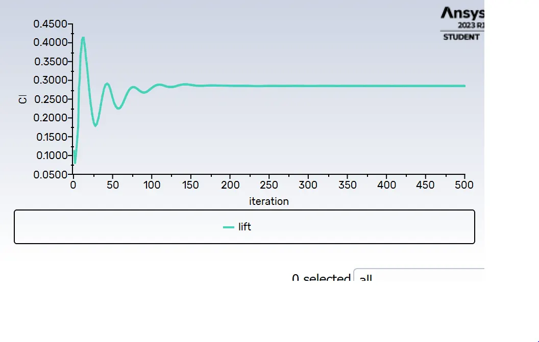
- Lift coefficient:
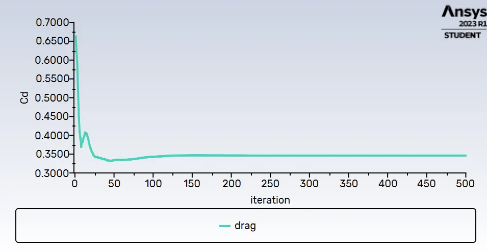
- Drag coefficient:
- Convergency:
Case III
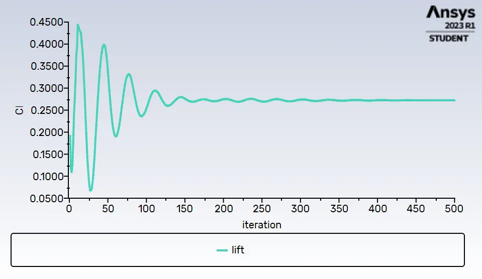
- Lift coefficient:
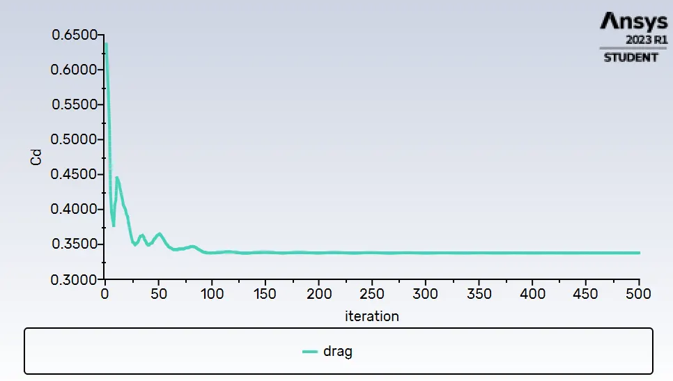
- Drag coefficient:
- Convergency:
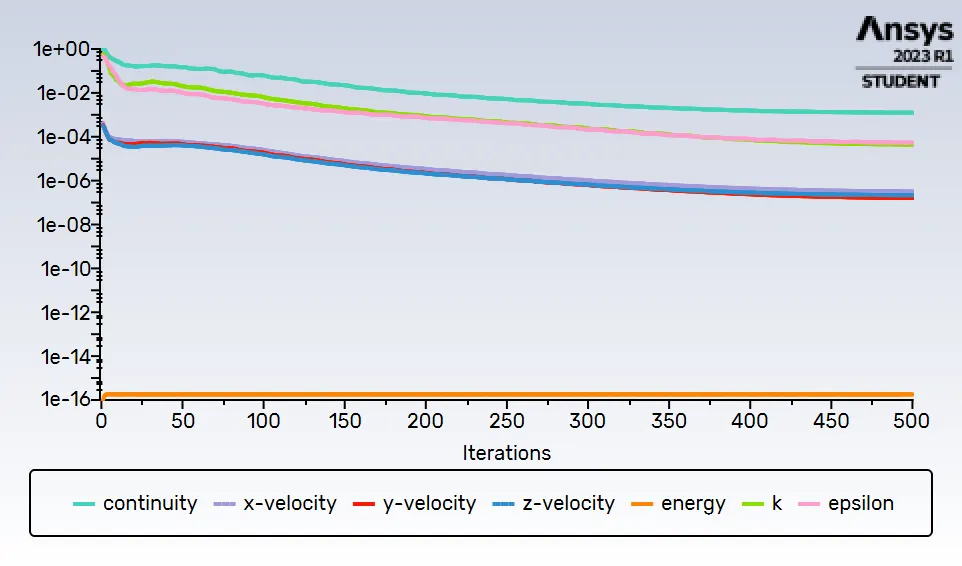
Reviewing the values obtained in each case, the results become lower. The values obtained are:
| Case I | Case II | Case III | |
| Drag coefficient | 0.3462 | 0.3377 | 0.3295 |
| Lift coefficient | 0.2849 | 0.2723 | 0.2665 |
That means the result values will become lower at the moment the grid size has been reduced more and more; this value reduction does not mean the value is more and more accurate, not until the values obtained has been compared with values obtained in different researches. However, the most accurate value that it has to be obtained is provided by the challenge statements, giving a drag coefficient value of 0.33 approximately. Taking this value, it could be assumed if the grid mesh is even more refined, the value obtained into the simulation will approximate to the real value. This asspumtion can be seen looking at the Case III result, where the drag coefficient obtained is equal to 0.3295, getting a error percentage of 0.05%.
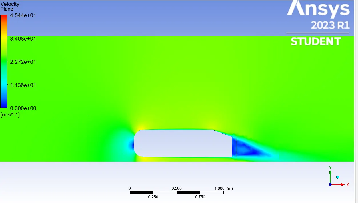
As the same way in the simulation is obtained a physical behavior where the pressure is negative over some body zones; to explain this behavior it is plotted the velocity and pressure values by means of a contour plot, which assings a determined colour regarding the parameter magnitude value.
- Velocity profile contour:
- Pressure profile contour:
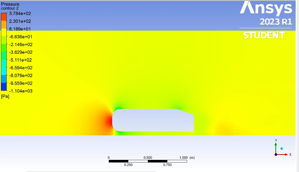
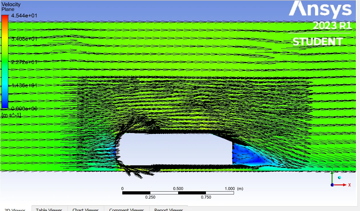
In the contour plots, the velocity in determined body regions is even higher than the flow velocity. Those regions are also the regions where the pressure tends to be negative and the main reason of this flow behavior is due to the flow shedding triggered by the body shape. The body has an stagnation point enough big that the stream lines lose their normal shape and the flow particles shock each other, disturbing the neighbor stream lines and boosting the flow particles outward. To understand clearer the explanation given, it is used vector plots, where it is shown how the particles over the weak regions tends to be led outward.
- Vectorial behavior of the velocity:
Right-side view:
Back view:
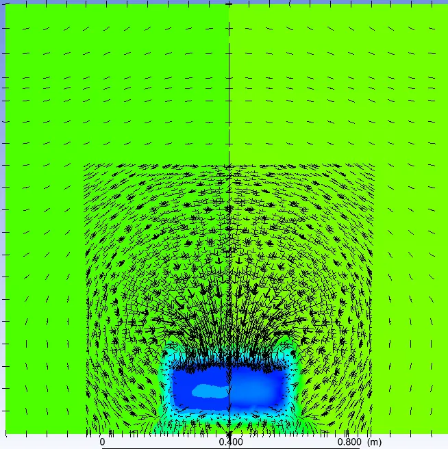
The rear body zone is also shown because of looking carefully at the pressure contour plot, it can be seen that exists negative pressure at the back zone, but the flow velocity magnitude is too low. This behavior is caused by the vorticity generated at this section and, the particle collisions generated in this parts. Even without velocity, the voticity waves reach to disturbing in a few quantity the pressure magnitude at the back cavity of the body.
CONCLUSIONS
The mesh grid independence is important to get accurate results in simulations, but there is not a standard mesh grid independence that helps obtain the most accurate mesh to carry out simulations. Due to that, it is necessary to iterate the mesh divisions in order to approximate the division to a mesh which reaches the most aproximated accurate results.
Wake regions over different aerodynamic objects are analyzed to get rid of the zones where the fluid is splitted due to the rough hapes or curves belonging to the body structure. Separation points are known as the points where the flow is distubed by the friction forces and flow shedding once an objet is brought into the zone where the flow is moving. These separation points are then in this simulation, the zones where the pressure magnitude is negative.
Ahmed body shape is very useful to demostrate the wake regions that it could have a car body if its surfaces are not softened.
REFERENCES
https://lms.skill-lync.com/programs/94933/23/what-is-yplus/knowledgebase
https://www.simscale.com/docs/validation-cases/aerodynamics-flow-around-the-ahmed-body/