Week 8 - Simulation of a backward facing step in OpenFOAM
Simulation of a backward facing step in OpenFOAM
AIM
The following project shows the simulation of a flow passing through the backward facing step geometry by means of OpenFoam.
OBJECTIVES
Simulate the flow behavior crossing inside a backward facing step geometry, using OpenFoam.
Determine the affects that using different grading factors could get.
ENGINEERING DEVELOPMENT
Geometrical Details and Boundary Conditions for Backward facing step:
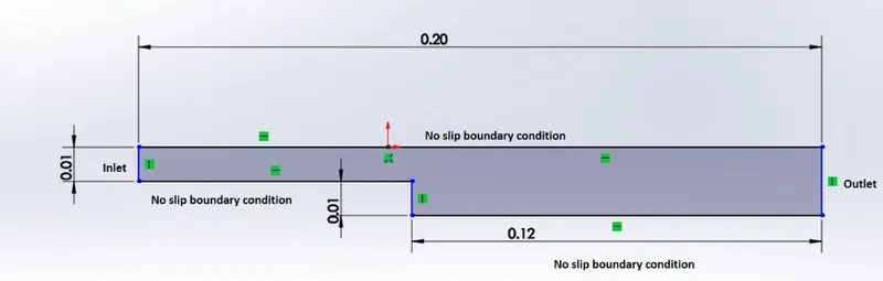
Also, the mesh must be divided in 200 nodes along the x axis and 20 nodes along y axis. To start the simulation, firstly the primitive variables and mesh parameters must be changed; Using the code steps showing in the images below can be changed the mesh (using gedit blockMeshDict & controlDict) the constant (gedit transportProperties), the velocity (gedit U) and the pressure (gedit p). icoFoam is used due to this command serves for simulating transient flows .
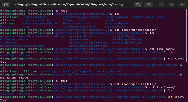
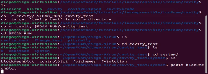
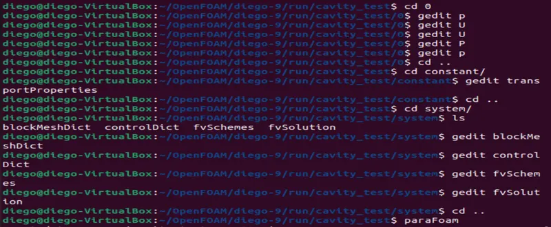
Now. using the gedit method in each item named, the code in each case will be:
Mesh - simple grading (1 1 1):
/*--------------------------------*- C++ -*----------------------------------*\
  =========                 |
  \\      /  F ield         | OpenFOAM: The Open Source CFD Toolbox
   \\    /   O peration     | Website:  https://openfoam.org
    \\  /    A nd           | Version:  9
     \\/     M anipulation  |
\*---------------------------------------------------------------------------*/
FoamFile
{
    format      ascii;
    class       dictionary;
    object      blockMeshDict;
}
// * * * * * * * * * * * * * * * * * * * * * * * * * * * * * * * * * * * * * //

convertToMeters 1;

vertices
(
    (0 0 0)             //0
    (0.08 0 0)          //1
    (0.08 0.005 0)      //2
    (0 0.005 0)         //3
    (0.08 0.01 0)       //4
    (0 0.01 0)          //5
    (0.2 0.01 0)        //6
    (0.2 0.005 0)       //7
    (0.2 0 0)           //8
    (0.2 -0.01 0)       //9
    (0.08 -0.01 0)      //10
    (0 0 0.01)          //11
    (0.08 0 0.01)       //12
    (0.08 0.005 0.01)   //13
    (0 0.005 0.01)      //14
    (0.08 0.01 0.01)    //15
    (0 0.01 0.01)       //16
    (0.2 0.01 0.01)     //17
    (0.2 0.005 0.01)    //18
    (0.2 0 0.01)        //19
    (0.2 -0.01 0.01)    //20
    (0.08 -0.01 0.01)   //21
);

blocks
(
    hex (0 1 2 3 11 12 13 14) (80 5 1) simpleGrading (1 1 1)

    hex (3 2 4 5 14 13 15 16) (80 5 1) simpleGrading (1 1 1)

    hex (2 7 6 4 13 18 17 15) (120 5 1) simpleGrading (1 1 1)

    hex (1 8 7 2 12 19 18 13) (120 5 1) simpleGrading (1 1 1)

    hex (10 9 8 1 21 20 19 12) (120 10 1) simpleGrading (1 1 1)
);

edges
(
);

boundary
(
    inlet
    {
        type patch;
        faces
        (
            (0 11 14 3)
            (3 14 16 5)
        );
    }
    outlet
    {
        type patch;
        faces
        (
            (7 6 17 18)
            (8 7 18 19)
            (9 8 19 20)
        );
    }
    upperWall
    {
        type wall;
        faces
        (
            (4 5 16 15)
            (6 4 15 17)

        );
    }
    lowerWall
    {
        type wall;
        faces
        (
            (0 1 12 11)
            (10 9 20 21)
            (1 10 21 12)
        );
    }

    frontAndBack
    {
        type empty;
        faces
        (
            (0 3 2 1)
            (3 5 4 2)
            (1 8 9 10)
            (2 7 8 1)
            (4 6 7 2)
            (11 12 13 14)
            (14 13 15 16)
            (21 20 19 12)
            (12 19 18 13)
            (13 18 17 15)
        );
    }
);
// ************************************************************************* //
Mesh - simple grading (0.2 5 1)
/*--------------------------------*- C++ -*----------------------------------*\
  =========                 |
  \\      /  F ield         | OpenFOAM: The Open Source CFD Toolbox
   \\    /   O peration     | Website:  https://openfoam.org
    \\  /    A nd           | Version:  9
     \\/     M anipulation  |
\*---------------------------------------------------------------------------*/
FoamFile
{
    format      ascii;
    class       dictionary;
    object      blockMeshDict;
}
// * * * * * * * * * * * * * * * * * * * * * * * * * * * * * * * * * * * * * //

convertToMeters 1;

vertices
(
    (0 0 0)             //0
    (0.08 0 0)          //1
    (0.08 0.005 0)      //2
    (0 0.005 0)         //3
    (0.08 0.01 0)       //4
    (0 0.01 0)          //5
    (0.2 0.01 0)        //6
    (0.2 0.005 0)       //7
    (0.2 0 0)           //8
    (0.2 -0.01 0)       //9
    (0.08 -0.01 0)      //10
    (0 0 0.01)          //11
    (0.08 0 0.01)       //12
    (0.08 0.005 0.01)   //13
    (0 0.005 0.01)      //14
    (0.08 0.01 0.01)    //15
    (0 0.01 0.01)       //16
    (0.2 0.01 0.01)     //17
    (0.2 0.005 0.01)    //18
    (0.2 0 0.01)        //19
    (0.2 -0.01 0.01)    //20
    (0.08 -0.01 0.01)   //21
);

blocks
(
    hex (0 1 2 3 11 12 13 14) (80 5 1) simpleGrading (0.2 5 1)
    hex (3 2 4 5 14 13 15 16) (80 5 1) simpleGrading (0.2 0.2 1)
    hex (2 7 6 4 13 18 17 15) (120 5 1) simpleGrading (5 0.2 1)
    hex (1 8 7 2 12 19 18 13) (120 5 1) simpleGrading (5 5 1)
    hex (10 9 8 1 21 20 19 12) (120 10 1) simpleGrading (5 5 1)
);

edges
(
);

boundary
(
    inlet
    {
        type patch;
        faces
        (
            (0 11 14 3)
            (3 14 16 5)
        );
    }
    outlet
    {
        type patch;
        faces
        (
            (7 6 17 18)
            (8 7 18 19)
            (9 8 19 20)
        );
    }
    upperWall
    {
        type wall;
        faces
        (
            (4 5 16 15)
            (6 4 15 17)

        );
    }
    lowerWall
    {
        type wall;
        faces
        (
            (0 1 12 11)
            (10 9 20 21)
            (1 10 21 12)
        );
    }

    frontAndBack
    {
        type empty;
        faces
        (
            (0 3 2 1)
            (3 5 4 2)
            (1 8 9 10)
            (2 7 8 1)
            (4 6 7 2)
            (11 12 13 14)
            (14 13 15 16)
            (21 20 19 12)
            (12 19 18 13)
            (13 18 17 15)
        );
    }
);
// ************************************************************************* //
Mesh parameters
/*--------------------------------*- C++ -*----------------------------------*\
  =========                 |
  \\      /  F ield         | OpenFOAM: The Open Source CFD Toolbox
   \\    /   O peration     | Website:  https://openfoam.org
    \\  /    A nd           | Version:  9
     \\/     M anipulation  |
\*---------------------------------------------------------------------------*/
FoamFile
{
    format      ascii;
    class       dictionary;
    location    "system";
    object      controlDict;
}
// * * * * * * * * * * * * * * * * * * * * * * * * * * * * * * * * * * * * * //

application     icoFoam;

startFrom       startTime;

startTime       0;

stopAt          endTime;

endTime         3;

deltaT          0.001;

writeControl    timeStep;

writeInterval   100;

purgeWrite      0;

writeFormat     ascii;

writePrecision  6;

writeCompression off;

timeFormat      general;

timePrecision   6;

runTimeModifiable true;


// ************************************************************************* //
Velocity parameters
/*--------------------------------*- C++ -*----------------------------------*\
  =========                 |
  \\      /  F ield         | OpenFOAM: The Open Source CFD Toolbox
   \\    /   O peration     | Website:  https://openfoam.org
    \\  /    A nd           | Version:  9
     \\/     M anipulation  |
\*---------------------------------------------------------------------------*/
FoamFile
{
    format      ascii;
    class       volVectorField;
    object      U;
}
// * * * * * * * * * * * * * * * * * * * * * * * * * * * * * * * * * * * * * //

dimensions      [0 1 -1 0 0 0 0];

internalField   uniform (0 0 0);

boundaryField
{
    inlet
    {
        type            fixedValue;
        value           uniform (0.5 0 0);
    }

    outlet
    {
        type            zeroGradient;
    }

    upperWall
    {
        type            noSlip;
    }

    lowerWall
    {
        type            noSlip;
    }

    frontAndBack
    {
        type            empty;
    }
}

// ************************************************************************* //
Dynamic pressure parameters
/*--------------------------------*- C++ -*----------------------------------*\
  =========                 |
  \\      /  F ield         | OpenFOAM: The Open Source CFD Toolbox
   \\    /   O peration     | Website:  https://openfoam.org
    \\  /    A nd           | Version:  9
     \\/     M anipulation  |
\*---------------------------------------------------------------------------*/
FoamFile
{
    format      ascii;
    class       volScalarField;
    object      p;
}
// * * * * * * * * * * * * * * * * * * * * * * * * * * * * * * * * * * * * * //

dimensions      [0 2 -2 0 0 0 0];

internalField   uniform 0;

boundaryField
{
   inlet
    {
        type            zeroGradient;
    }

    outlet
    {
        type            fixedValue;
        value           uniform 0;
    }

    upperWall
    {
        type zeroGradient;

    }

    lowerWall
    {
        type zeroGradient;

    }

    frontAndBack
    {
        type empty;
     }

}
// ************************************************************************* //
Transport properties
/*--------------------------------*- C++ -*----------------------------------*\
  =========                 |
  \\      /  F ield         | OpenFOAM: The Open Source CFD Toolbox
   \\    /   O peration     | Website:  https://openfoam.org
    \\  /    A nd           | Version:  9
     \\/     M anipulation  |
\*---------------------------------------------------------------------------*/
FoamFile
{
    format      ascii;
    class       dictionary;
    location    "constant";
    object      transportProperties;
}
// * * * * * * * * * * * * * * * * * * * * * * * * * * * * * * * * * * * * * //

transportModel  Newtonian;

nu              [0 2 -1 0 0 0 0] 1e-05;

// ************************************************************************* //
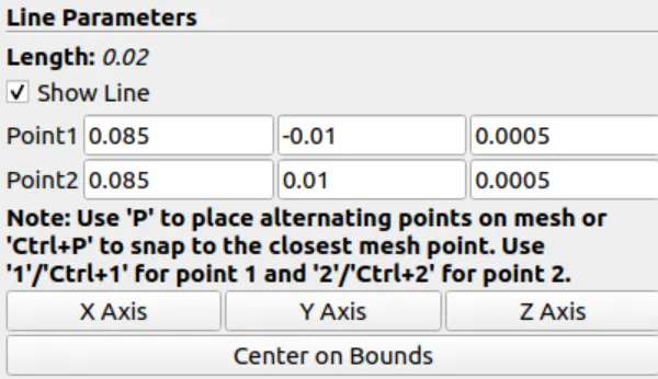
Finally, paraFoam is used for opening OpenFoam program and visualizing the simulation. The velocity profile along 0.085 m from the geometry can be fixed on the OpenFoam view as is shown in the following image.
RESULTS
At a grading factor of (1 1 1), the mesh will look like:
MESH AT GRADING FACTOR (1 1 1)

Being a refined mesh along the geometry and allowing performing the simulation. Once the simulations is ran up, the velocty and dynamic pressure will start in a high state but, once the flow passing through the goemetry, those two is going to become less and less, due to the fluid lacks.
VELOCITY AT GRADING FACTOR (1 1 1)

PRESSURE AT GRADING FACTOR (1 1 1)

Now, the second simulation shown below is carried out using a grading factor (0.2 5 1); the mesh in this case decreases its size in some spots and increases in others.
MESH AT GRADING FACTOR (0.2 5 1)

This change of grading will change the accuracy of some geometry spots, because of the mesh will center its analysis in high measure at the little cells. Velocity and dynamic pressure shows more red points in this simulation than the previous simulation.
VELOCITY AT GRADING FACTOR (0. 5 1)

PRESSURE AT GRADING FACTOR (0.2 5 1)

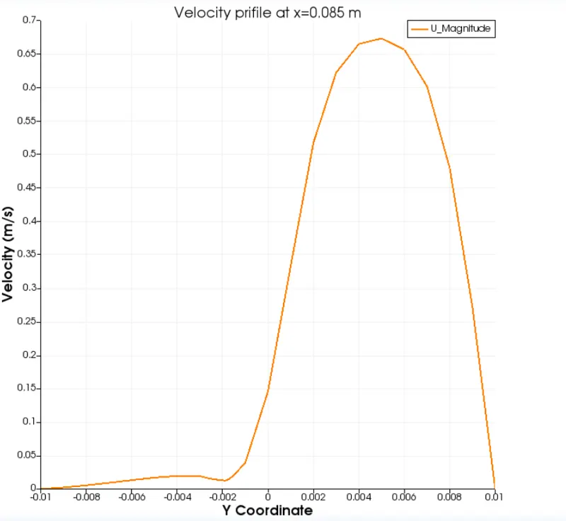
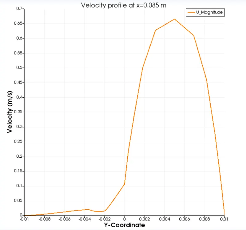
Furthermore, the velocity profile at x=0.085m change in both simulations due to the mesh refinement. The fisrt image the velocity profile looks softer than the second one and it can be compared in each profile peak.
GRADING FACTOR (1 1 1)
GRADING FACTOR (0.2 5 1)
CONCLUSIONS
The mesh can be affected by the grading factor and, the result accuracy too. Likewise, the grading factor variation aims to analyze determined points in the simulation, especially critical points where it is known by experience the solid or the part are going to suffer some load or movement due to the primitive variables.
It must be taken into account the way to carry out computational simulations, because of the mesh have to be correctly changed or the results might vary in a wrong way.
That's it, thanks for reading.
REFERENCES