Week 4 Challenge : CFD Meshing for BMW car
CFD Meshing for BMW M6 Car
AIM
The whole BMW M6 car's body will be fixed and meshed in this project, according to the required mesh-cell side size. Car modeling normally has too complex shapes so that the flow behavior over it, is difficult to analyze by calculating continuum equations without computational devices; Likewise, all car designers must consider through their computer modeling design, that the car must have an approximately smoothness shape which be able to get meshed without having troubles once the CAD model created has been entered into any fluid analysis software. Thus, ANSA provides a good topology section that can fix the problems generated in the CAD modeling process; besides that, ANSA also generates the mesh over each CAD model component, depending on the requirements that the designer has projected.
Then, the BMW 6M car provided by the challenge statements must be checked and meshed, due to the initial conditions that the car has, does not accomplish a correct CFD geometry; furthermore, each car part must have its mesh-cell side size, which will be put in and refined, to remain the smoothness from each car part surface.
OBJECTIVES
- Fix and build the required surfaces that the car model needs to get a smooth geometry.
- Use the mesh tools provided by the software to refine and mesh the geometry surfaces according to the mesh-cell side size imposed by the challenge statements.
- Obtain the complete car shape by using new tools that make the way to check and meshing complex geometries as car models easier.
ENGINEERING DEVELOPMENT
Using the topo tools shown in all the projects previously performed (projects are named in the references section), the car surfaces fit as it is shown in the following picture.
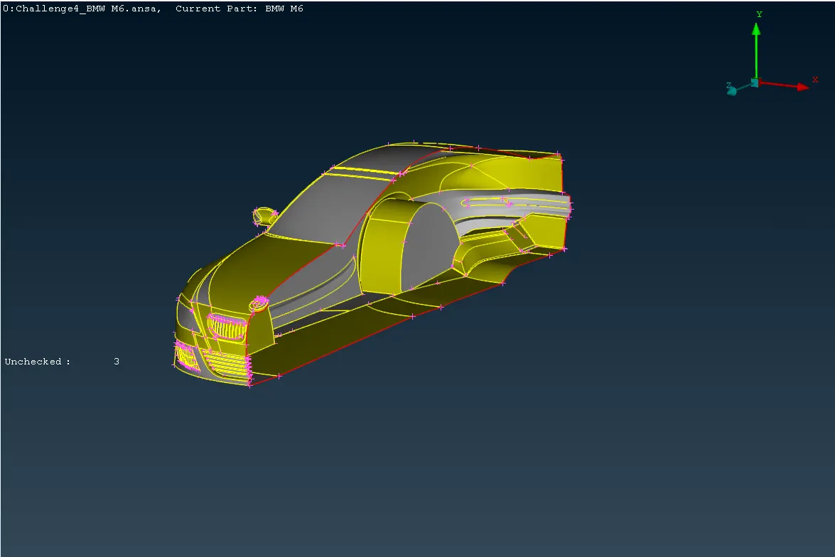
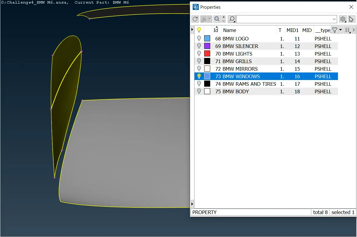
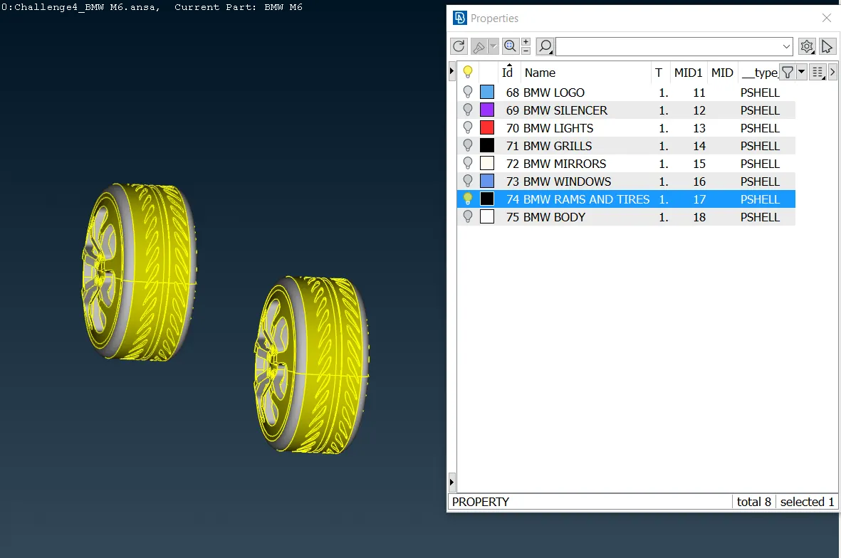
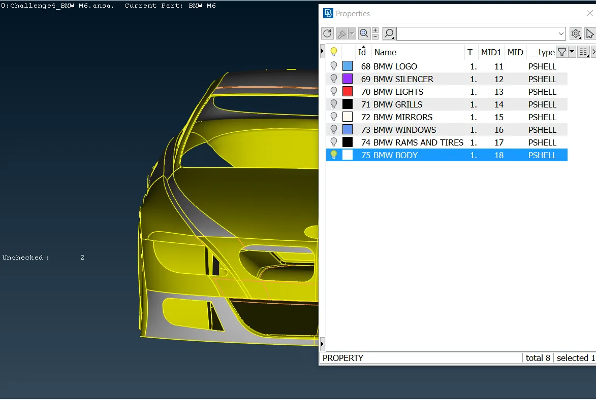
The car is split to fix the sections that are geometrically wrong easier. Also, the fixed surfaces are named depending on the function each one will have on the car; In the image below, PID function is already used and each part from the car is underscored by a color.
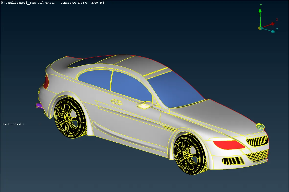
Thus, the main car parts are:
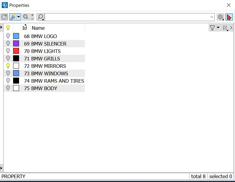
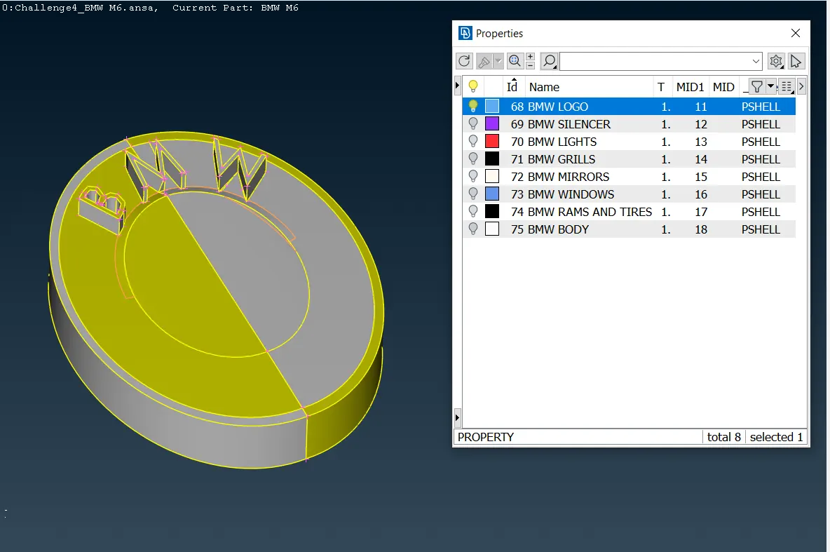
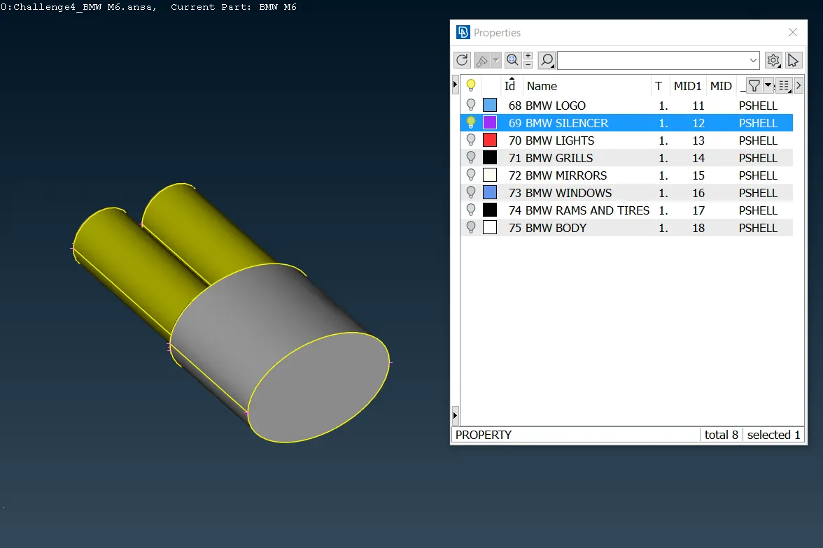
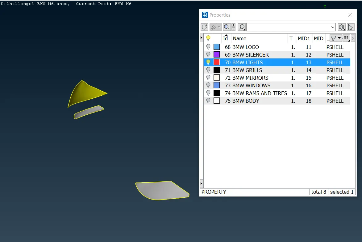
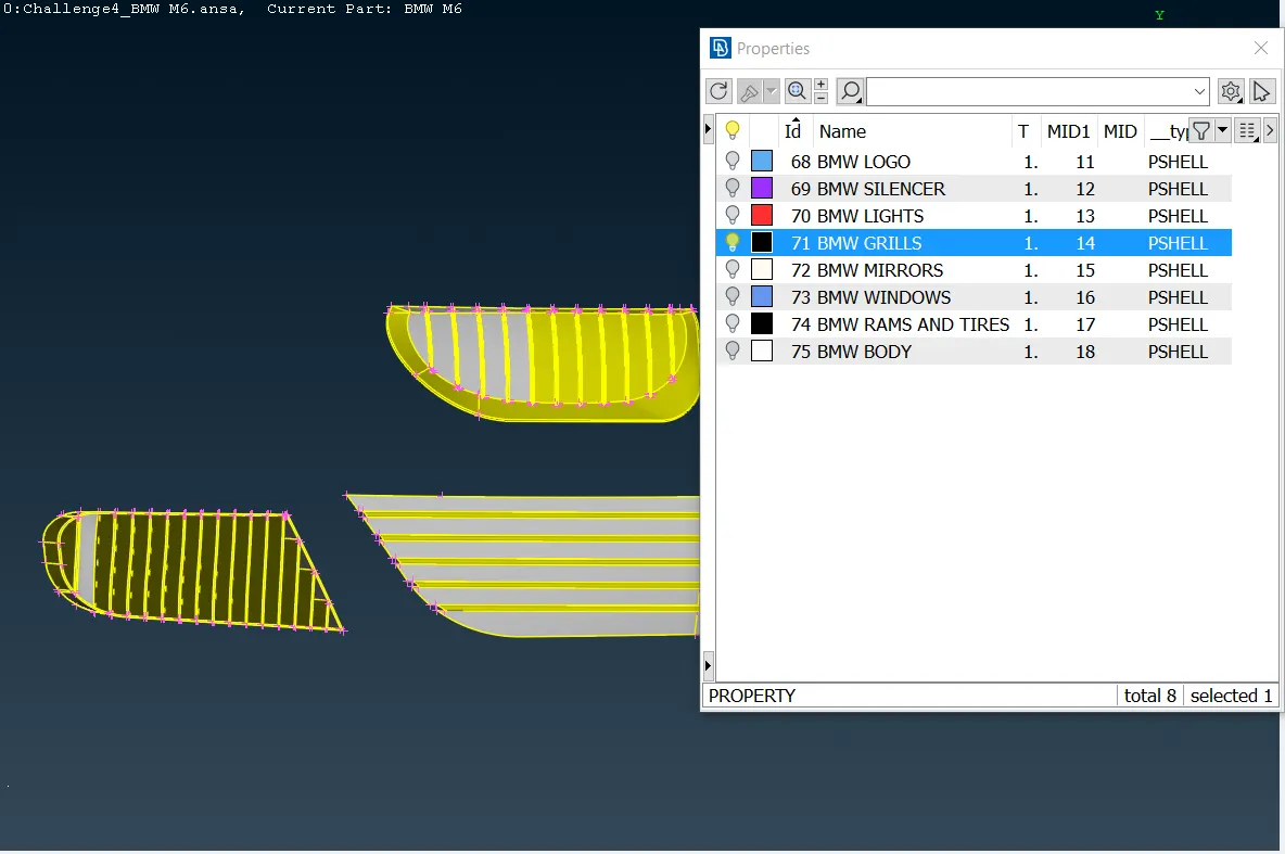
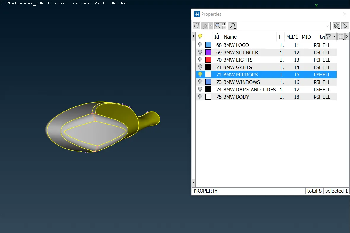
Likewise, each car part looks like the following eight exposed pictures:
- BMW LOGO:
- BMW SILENCER:
- BMW LIGHTS:
- BMW GRILLS:
- BMW MIRRORS:
- BMW WINDOWS:
- BMW RIMS AND TYRES:
- BMW BODY:
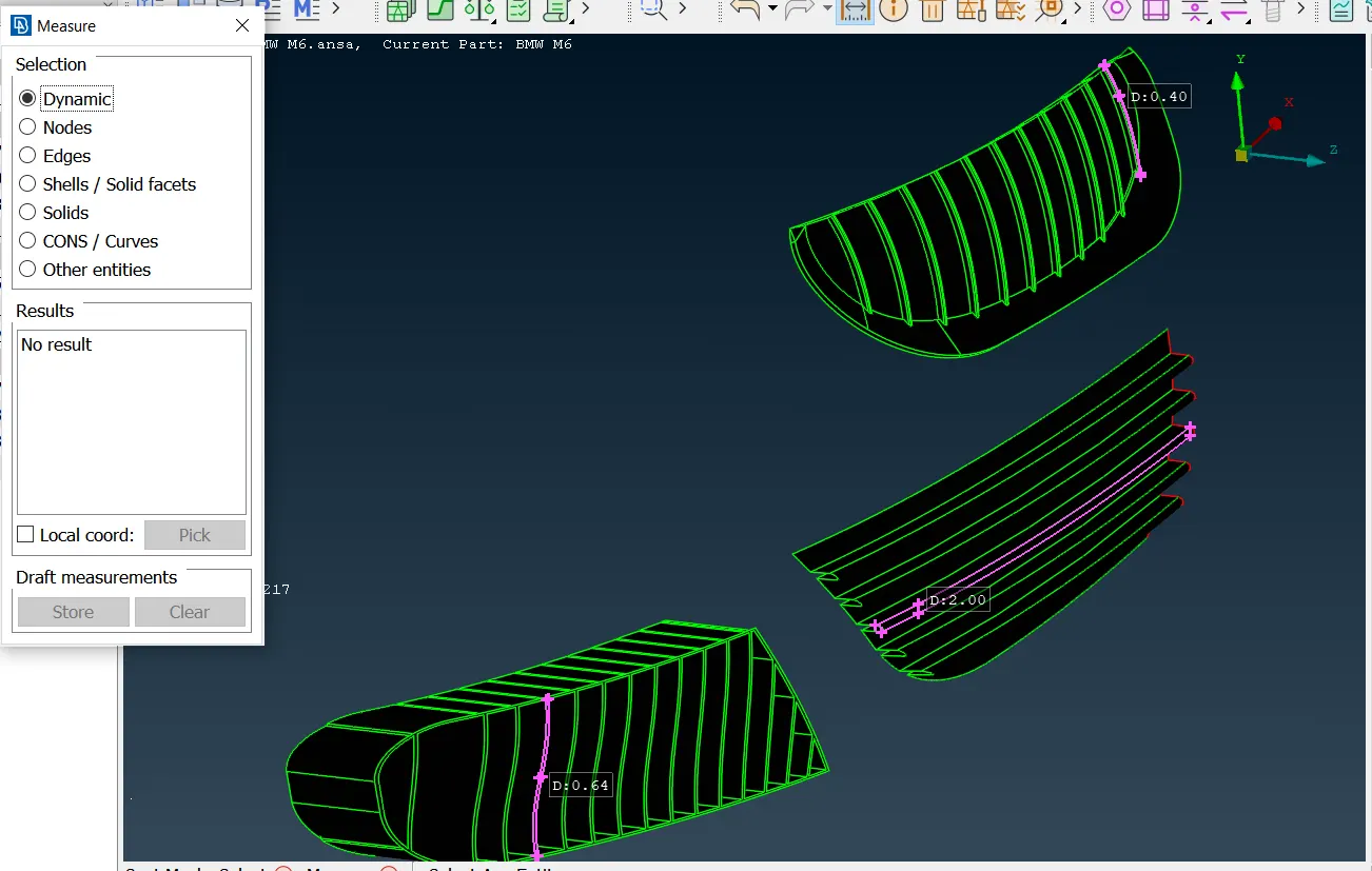
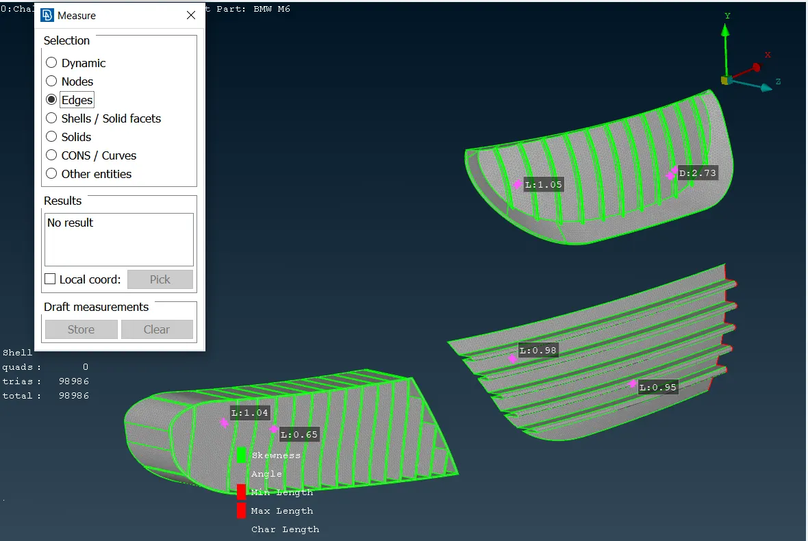
Once all the car parts are fixed and named, the next step is to measure the minimum size that each car part has, to enter the minimum and maximum length; for instance, the picture below shows the minimum measurements that the car grills have and these measures will serve for limiting the mesh-cell side sizes.
In the same way, the other components must be measured, until all the minimum lengths are obtained. The following table exposes the average mesh-cell side size that every cell should have, with the minimum, maximum length, and cell skewness altogether. The maximum length will always be the average size plus one.
| BMW M6 Component | Mesh-cell side size (mm) | Minimum Length | Maximum length | Skewness |
| Body | 3 | 1 | 4 | 1 |
| Lights | 4 | 3 | 5 | 1 |
| Grills | 1 | 0.3 | 2 | 1 |
| Rims and Tyres | 2 | 0.5 | 3 | 1 |
| Optical rearview mirror | 2 | 0.5 | 3 | 1 |
| Window | 2 | 0.5 | 3 | 1 |
| Silencer | 3 | 2 | 4 | 1 |
| Logo | 1 | 0.1 | 2 | 1 |
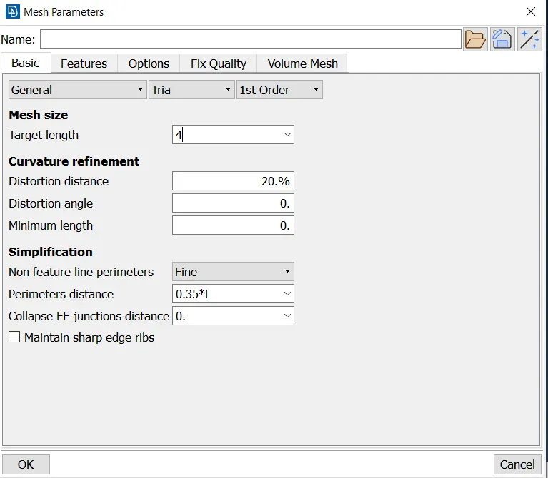
Now, the mesh-cell side sizes must be entered in the mesh parameters section and, the other parameters shown in the table must be entered in the mesh quality section. At the end of this project the mesh quality sheets performed for each component are attached, as well as the mesh parameter window is shown in the following picture.
Surface components sometimes can get problems due to the surface curvatures or too low sizes, it is required to use some meshing methods provided by ANSA, which allow varying the mesh-cell size and the mesh-cell qualities. Some of these are shown in the image below.
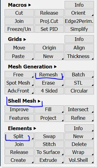
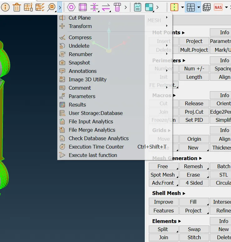
The most common meshing tool for improving the mesh qualities is found in the shell mesh and, it is known as "Reconstruct"; this tool remesh the initial mesh generated, considering the off elements that the initial mesh did not take into account. To get the other half part of the car, it is used a new tool named as "Transform", this one is located in the following section:
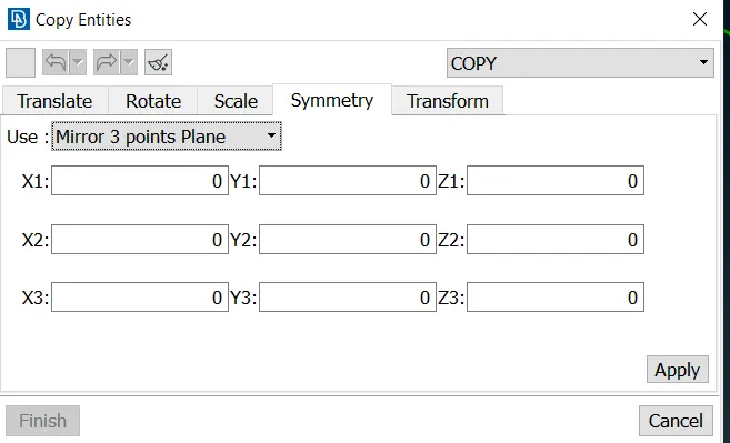
Transform has three tool options which are copy, move, and link; the other car half is obtained by using the copy option, then, using the symmetry option, and finally, taking 3 arbitrary points from the car middle boundary.
Finally, at the moment all the components do not have any off element and the whole cells created have been refined, including the mesh cells which are located in the boundaries, the final step is to create the space environment to simulate the flow field; however, the computational resources that currently have does not allow generating this environment.
RESULTS
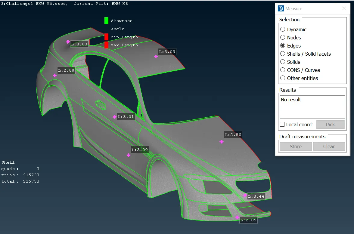
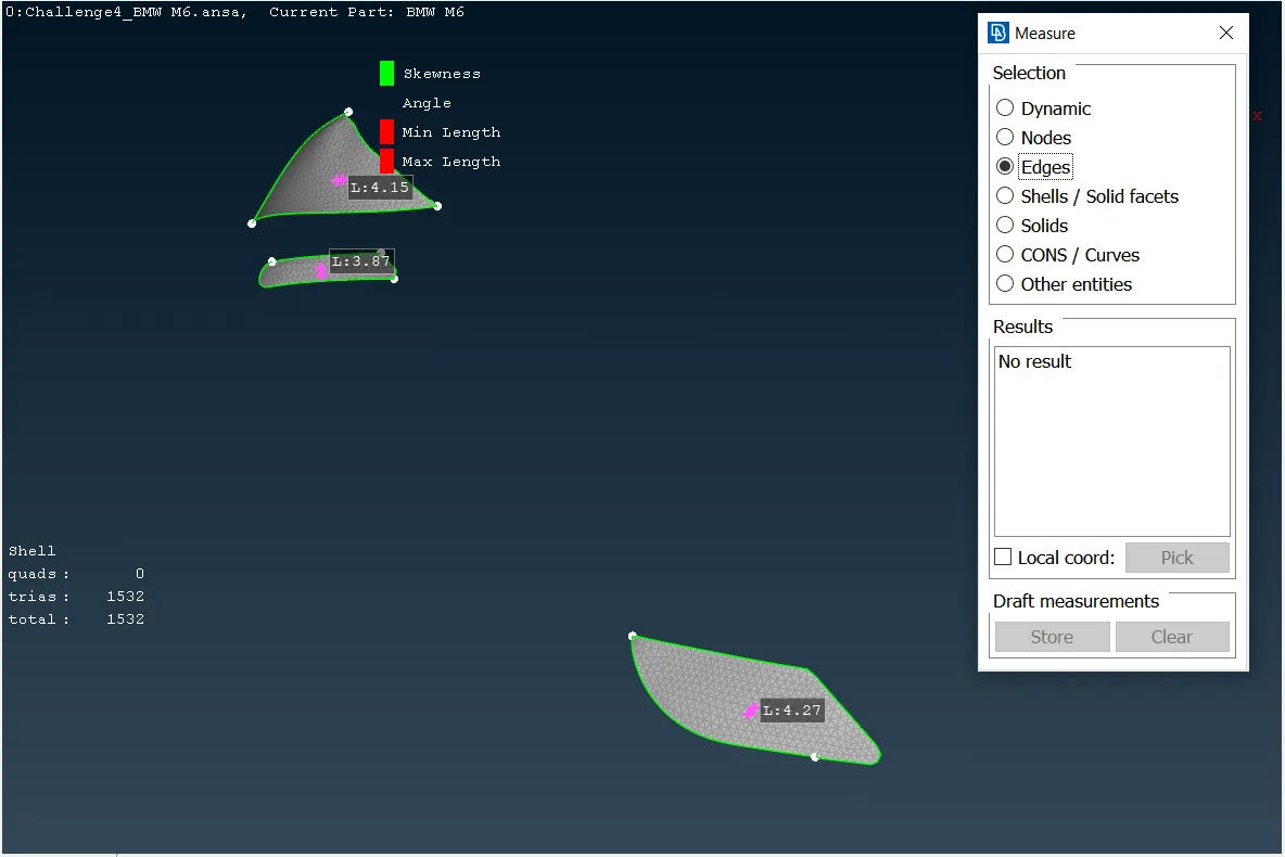
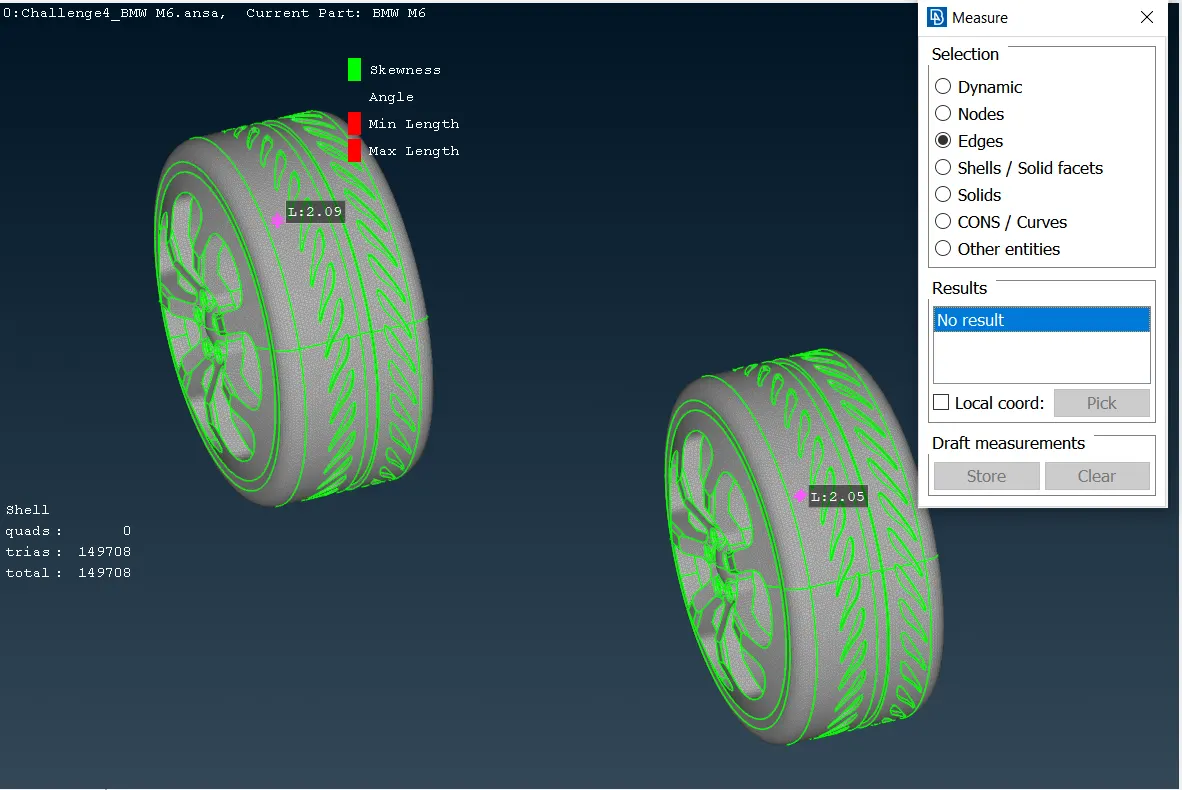
As it was described above, the off elements must not appear in the finishing meshing from each car component. So, the following images show that every car part does not have any single off element that affects the mesh parameters and quality. The car components look like:
Body (Size: 3 mm):
Lights (Size: 4 mm):
Grills (Size: 1 mm):
Rims and tyres (Size: 2 mm):
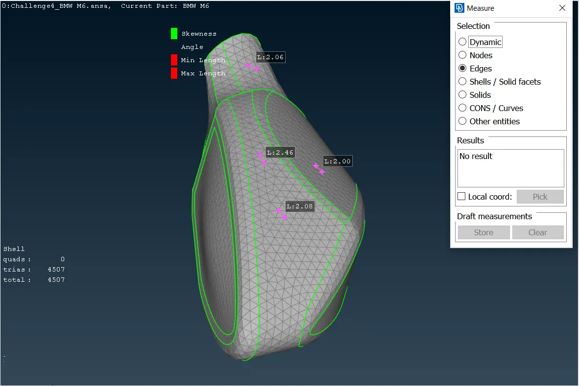
Optical rearview mirror (Size: 2 mm):
Windows (Size: 2 mm):

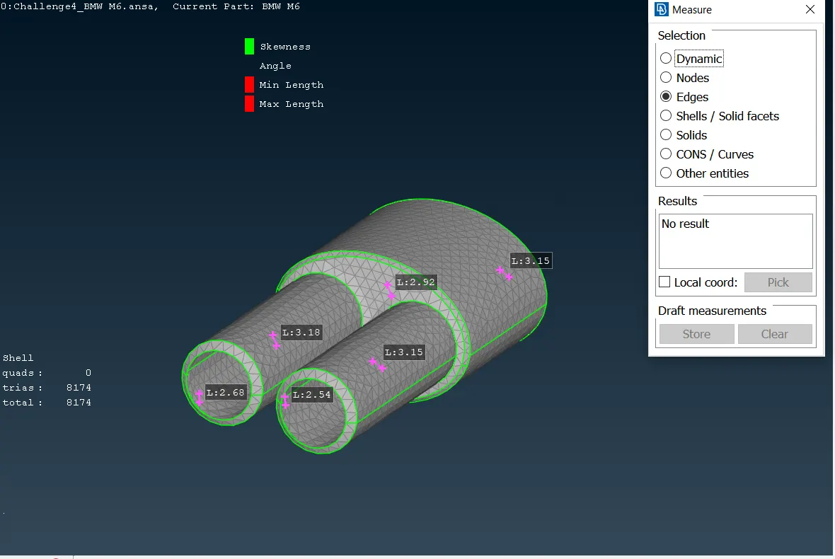
Silencer (Size: 3 mm):
Logo (Size: 1 mm):
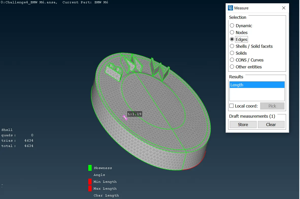
It can also be seen that it was taken some mesh cell side sizes in each component, in order to demonstrate the cell sizes are within the mesh quality limits exposed in the table exposed above. Then, the number of elements determined is shown in the following table.
| BMW M6 COMPONENT | NUMBER OF ELEMENTS |
| Body | 215730 |
| Lights | 1532 |
| Grills | 98986 |
| Rims and tyres | 149708 |
| Optical rearview mirror | 4507 |
| Windows | 61437 |
| Silencer | 8174 |
| Logo | 4634 |
| TOTAL PER HALF BODY | 544708 |
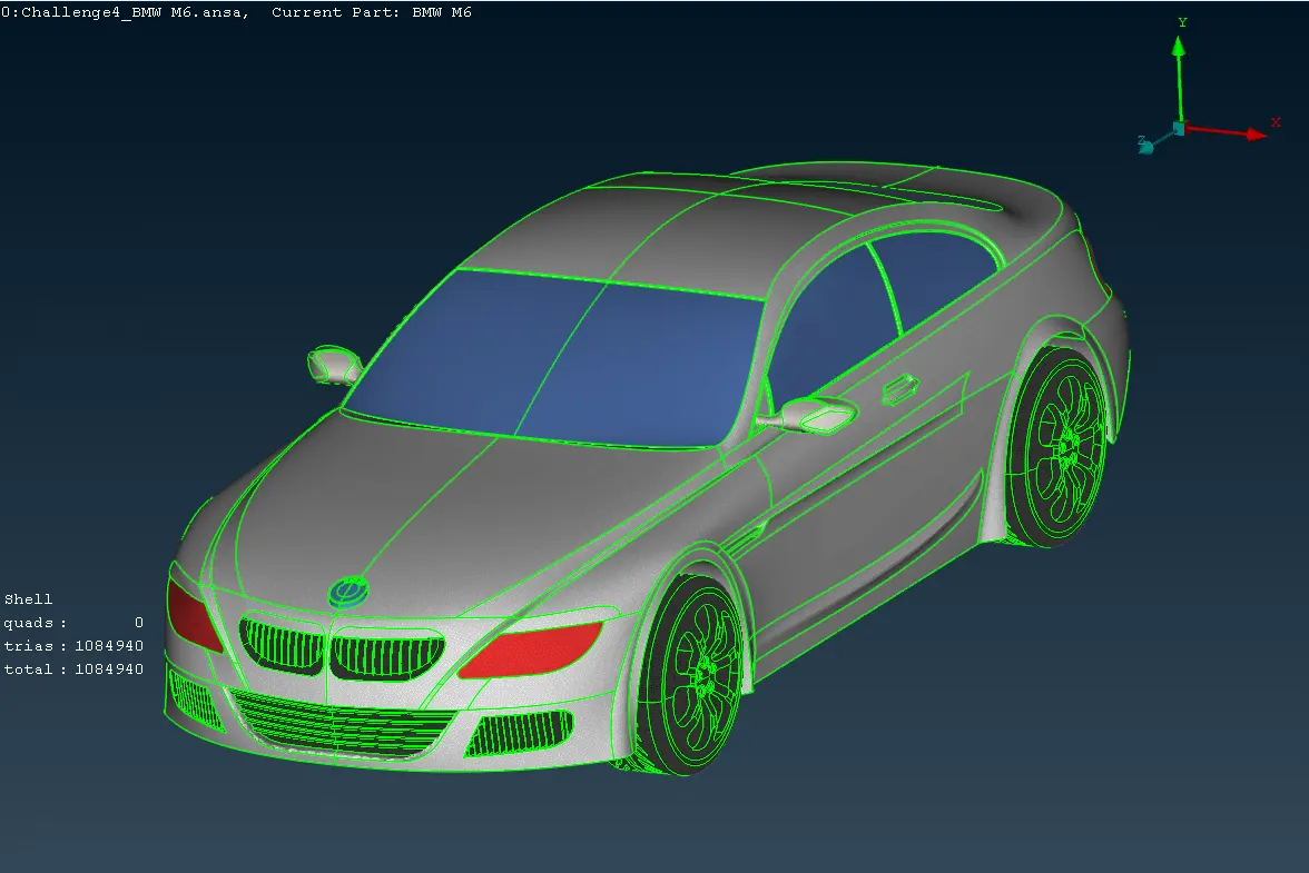
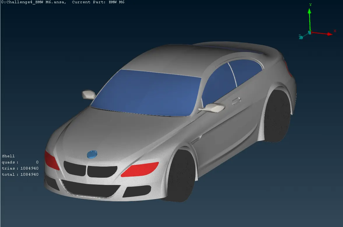
Furthermore, the finishing BMW model obtained from the symmetry step shown above looks like the following images:
Complete body
CONCLUSIONS
Car modeling can easily be performed in any CAD program, however, it could carry too much work to fix the surfaces that the CAD program does not consider if the car designer does not check these issues before taking the model into a CFD program.
The flow field modeling requires high computational resources because of the mesh elements must first be volumetric and, each volumetric element must be small enough to get an accurate result of the physical magnitude value that the primitive parameters have within the cubic cell.
Complex geometries always include sections that the designer must review to mitigate the mesh skewness, once the designer has started meshing the CAD model; ANSA allows to check these sections by pointing them out using the "off elements" tool.
REFERENCES
https://skill-lync.com/student-projects/week-2-challenge-surface-meshing-on-a-pressure-valve-451
https://skill-lync.com/student-projects/week-3-challenge-cfd-meshing-on-turbocharger-411