Week 2 Challenge : Surface meshing on a Pressure valve
1. Aim
The aim of this challenge was to perform surface meshing on a Pressure valve based on pre-determined entities, such as target length values of 1mm, 3mm and 5mm using element type as Tria, in ANSA-CFD.
2. Procedure
The approach adopted towards performing surface meshing for the given Pressure valve model in ANSA-CFD involved the following steps:
- Import the given model from the concerned directory containing the ".ansa" file extension using the "Open" option under the "File" menu.
- After the model is loaded and appears in the "workspace", the "TOPO" module responsible for geometry creation, manipulation and clean up needs to be enabled.
- For the given model, it was realised that the geometry had a number of missing faces from existing surfaces, also identified as "Single Cons" errors when the "Geometry Checks" was performed, which were required to be reconstructed as part of the Topology cleanup, in this case using the "New" button under the list of "Faces" button functionalities. The "New" button consisted of different options or algorithms to essentially define the missing face/surface such as "COONS" which makes use of an interpolation principle based on selected boundary curves, "EXISTING SURF" for drawing a new face on an existing surface, "PLANAR" for a planar face (as the name suggests) and "FITTED" for a non-planar face with regards to the selected boundaries. All of the above alternatives were made use of depending on the characteristics of the missing faces along with the "LOOP" option enabled in certain cases especially when "COONS" option was preferred as it was able to predict the list of edges, perimeters or curves forming a close loop thereby saving effort and time. After completion of reconstructing new faces, it was observed that some of the surfaces intersected at rather sharp angles indicating that these areas could give rise to problems at the time of meshing with smaller element sizes. Therefore, lines and/or curves belonging to these surfaces were considered to be deleted using the "Cut" button under the list of "Faces" button functionalities such that those surfaces were then merged into one surface.
- At this stage and for the given model, no further geometry associated operations were required, as was also confirmed by executing another "Geometry Checks" except for "Triple Cons" which were required surfaces to close the model, and surfaces comprising particular bodies were assigned within the PID manager such as "Valve Head", "Spring", "Valve Stem", "Base Surface", "Inlet", "Outlet" and "Body", which also would act as boundary conditions during the pre-processing stage for a CFD simulation, before proceeding to the next step of surface meshing. It should be noted that due to the complex features of the given model and four out of seven components forming the internal mechanism of the Pressure valve, visibility tools such as "Or", "And", "Not", "!Not", "Invert", "All" and "Lock" were made use of to enable ease in selection of the concerned faces as part of their respective bodies.
- Meshing operations were defined within the "MESH" module which for ANSA-CFD contains buttons for both surface and volume meshing within the same window.
- The first functionality selected was "Init" under the list of "Perimeters" buttons to essentially reset the "NUMBER" and "LENGTH" aspects of selected perimeters which is also recommended as a best practice when a new mesh needs to be created from an existing or incorrect mesh in order to avoid dealing with issues such as conflicts.
- The meshing parameters were defined by accessing the "Auto CFD" option within the "Spacing" functionality under the list of "Perimeters" button functionalities which is to define the distribution of nodes based on element length value. For the selected feature, two options are available, "Perimeters" to set the element length value on CONS (Curves On Surfaces) and "Macros" to perform the same operation on "FACE,SHELL". In the given case, using either of the options, values of "Minimum Target Length" and "Maximum Target Length" under the "Spacing Parameters" tab of "CFD SPACING PARAMETERS" window were set to 3mm and 7mm for a target length of 5mm, 1mm and 5mm for a target length of 3mm and 0.5mm and 2mm for a target length of 1mm respectively.
- The above step also reflects in the values of the same attributes when "Mesh Parameters" option is selected with the only change being the element type which was selected as "Tria", and step "7." needed to be repeated within the "Quality Criteria" button functionality by enabling "min length" and "max length" quantities and reusing the previously mentioned values.
- Since, the diameter of the "Spring" component's cross-section was approximately 3.4mm and the "Valve Head" component offered a surface of high curvature, the values of "Minimum Target Length" and "Maximum Target Length" under "Mesh Parameters" and "CFD SPACING PARAMETERS" of the "Auto CFD" option within the "Spacing" functionality for both "Perimeters" and "Macros" items as well as the "min length" and "max length" under "Quality Criteria" were set to 0.5mm and 2mm for a target length of 1mm respectively for a better definition and resolution of the concerned meshed surfaces.
- Post-definition of the necessary meshing parameters, the "Select" and "Visible" sub-option within the "CFD" functionality under the list of "Mesh Generation" button functionalities were selected to generate the required surface meshes on the different components of the Pressure valve.
3. Results
Fig. 1, and Fig. 2, Fig. 3 and Fig. 4 represents the Pressure valve geometry (after Topology cleanup and PID assignment) and its surface meshes for the three different target lengths of 1mm, 3mm and 5mm respectively. It can be observed that the element type across the model is "Tria" and on using the "Measure" tool with option set to "Nodes" it was found out that the average distance between two nodal points over the entire surface was representing their respective target length values approximately. Additionally, Fig. 5 and Fig. 6 also indicate the surface meshes using the target length value of 1mm for the valve head and spring components respectively.
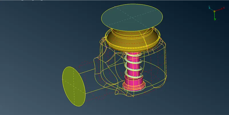
Fig. 1: Pressure Valve Geometry (Main Body is transparent to reveal internal components)
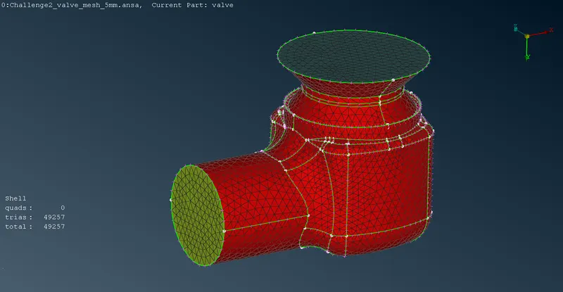
Fig. 2: Surface Mesh of Pressure Valve for target length of 5mm
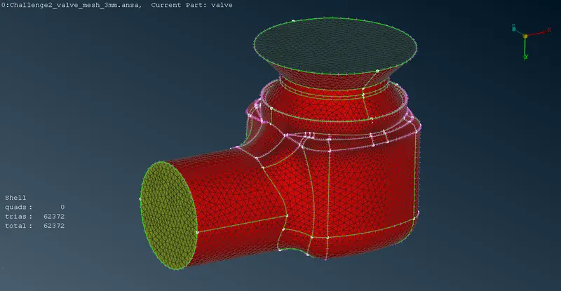
Fig. 3: Surface Mesh of Pressure Valve for target length of 3mm
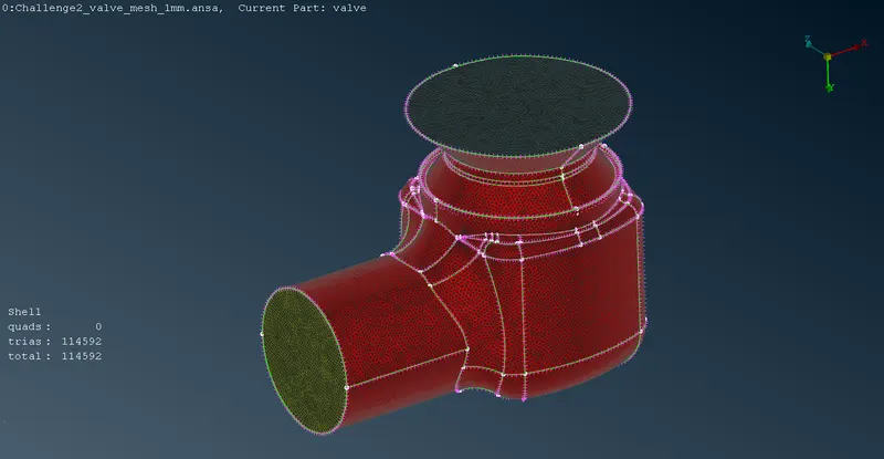
Fig. 4: Surface Mesh of Pressure Valve for target length of 1mm
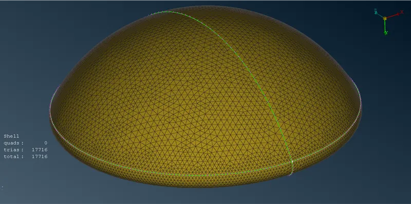
Fig. 5: Surface Mesh of Valve Head component using target length of 1mm
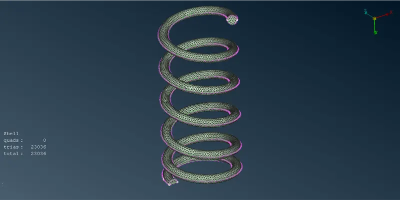
Fig. 6: Surface Mesh of Spring component using target length of 1mm
4. Learning Outcomes
The learning outcomes from this challenge can be outlined as follows:
- Identification of missing features and errors in geometry using "Geometry Checks" and construction or re-construction of the same using different modules buttons under "Topo" section as part of the Topology cleanup operation.
- Assignment of PIDs through appropriate collection of surfaces belonging to the concerned body offering better control on meshing requirements as well as providing the benefit of re-using them at the time of defining boundary conditions.
- Use of "Init" functionality as a best practice method before defining meshing parameters.
- Setting of different parameters under various button functionalities such as "Auto CFD", "Mesh Parameters" and "Quality Criteria" to set minimum and maximum target length values of elements and the element type.
- Creation of mesh using the "Select" and "Visible" sub-options within the "CFD" functionality.
5. Conclusion
The surface meshing of the given Pressure valve model and its components using different button functionalities was well understood using ANSA-CFD. It was realised that a surface mesh described on the values of minimum and maximum target length as well as the element type can be created and of all the target length values utilised in this assignment, the 1mm target length value would perhaps be a preferred choice owing to better meshing resolution and possibly minimised numerical diffusion, however, the results can be better confirmed through a mesh sensitivity analysis that would target required accuracy as well as maintain the possible number of nodes/elements that are allowed to be solved for on the concerned application.