Project 1 : CFD Meshing for Tesla Cyber Truck
1. Aim
The aim of this challenge was to perform surface meshing on a Tesla Cyber truck model and on a wind tunnel surrounding the same based on selected target length values of its different components using element type as Tria, as well as appropriate selection of the volume that contains the vehicle and its surroundings with the wind tunnel for volumetric meshing in ANSA-CFD.
2. Procedure
The approach adopted towards performing surface meshing of the given Tesla Cyber truck model and the wind tunnel as well as preparation for volumetric meshing for the combined entities in ANSA-CFD involved the following steps:
- Import the given model from the concerned directory containing the ".ansa" file extension using the "Open" option under the "File" menu.
- After the model is loaded and appears in the "workspace", the "TOPO" module responsible for geometry creation, manipulation and clean up needs to be enabled.
- Before performing any surface creation or deletion operations, it was decided to make use of the "Topo" button under the list of "Faces" button functionalities to automatically create the necessary topological conditions between adjacent CONS on the entire model.
- New surfaces were then defined by accessing the "New" button under the list of "Faces" button functionalities that consisted of different options or algorithms to essentially define the missing face/surface such as "COONS" which makes use of an interpolation principle based on selected boundary curves, "EXISTING SURF" for drawing a new face on an existing surface, "PLANAR" for a planar face (as the name suggests) and "FITTED" for a non-planar face with regards to the selected boundaries. All of the above alternatives, except for "EXISTING SURF", were made use of depending on the characteristics of the missing faces along with the "LOOP" option enabled in certain cases as it was able to predict the list of edges, perimeters or curves forming a close loop thereby saving effort and time. Alternatively, the "Fill Hole" button under the list of "CONS" button functionalities was also implemented to create surfaces between the outlined Single CONS. There were a few surfaces where the "New" or the "Fill Hole" button functionalities could not be implemented directly as the detected surfaces using the previously mentioned algorithms did not close the required surfaces satisfactorily, and in those cases "Hot Points" were inserted on the "CONS" using the "Project" button under the list of "Hot Points" button functionalities to define a new Node or Hot Point. Similar button functionality of "Project" under the list of "CONS" button functionalities was also made use of to both split a surface overlapping into another surface that could later be deleted using the "Delete" button of the Geometry Group, and to define a list of surfaces belonging to a particular part. Another button by the name "Intersect" under the list of "Faces" button functionalities was executed to define the intersection between two groups of faces that penetrated each other, in this case at an angle, and consequently to specify a closed area between them, followed by the unnecessary surfaces being deleted using the "Delete" button of the Geometry Group.
- The above "step 4." ensured that all the overlapping and missing surfaces, including "Single Cons" errors, were well taken care of but there were also a number of "Triple Cons" errors present in the model which was revealed when the "Geometry Checks" was performed again, some of which contained surfaces of different parts that were not necessary and in other cases being additional surfaces that would lead to creation of separate volumes during the preparation of volumetric meshing, both of which were accordingly removed using the "Delete" button of the Geometry Group followed by repeating "step 4." wherever necessary.
- At this stage and for the given model, no further geometry associated operations were required, as was also confirmed by executing another "Geometry Checks" except for a few "Triple Cons", and accordingly surfaces belonging to different parts or bodies for the given vehicle model were assigned within the PID manager such as "Main_Body", "Underbody", "Head_Lights", "Tail_Lights", "Rims", "Tyres", "Windows", "Doors" and "Door_handles", all of which would also essentially act as wall boundary conditions during the pre-processing stage for a CFD simulation, before proceeding to the next step of surface meshing. It should be noted that due to the complexity of features of the given vehicle model, visibility tools such as "Or", "And", "Not", "!Not", "Invert", "All" and "Lock" were made use of to enable ease in selection of the concerned faces as part of their respective bodies.
- Meshing operations were defined within the "MESH" module which for ANSA-CFD contains buttons for both surface and volume meshing within the same window.
- The first functionality selected was "Init" under the list of "Perimeters" buttons to essentially reset the "NUMBER" and "LENGTH" aspects of selected perimeters which is also recommended as a best practice when a new mesh needs to be created from an existing or incorrect mesh in order to avoid dealing with issues such as conflicts.
- The meshing parameters were defined by accessing the "Auto CFD" option within the "Spacing" functionality under the list of "Perimeters" button functionalities which is to define the distribution of nodes based on element length value. For the selected feature, two options are available, "Perimeters" to set the element length value on CONS (Curves On Surfaces) and "Macros" to perform the same operation on "FACE,SHELL". In the given case, using either of the options, values of "Minimum Target Length" and "Maximum Target Length" under the "Spacing Parameters" tab of "CFD SPACING PARAMETERS" window were set to the minimum and maximum length values as found on each of the above mentioned PIDs using the "Measure" utility tool while the target lengths were defined as seen in the table below:
Table 1: PIDs and their surface mesh target length values for the Tesla Cyber truck modelSr. No. PID Target Length [mm] 1 Body 3 2 Underbody 3 2 Head_Lights 4 3 Tail Lights 4 5 Rims 2 6 Tyres 2 8 Windows 2 9 Doors 3 10 Door_handles 3 - The above step also reflects in the values of the same attributes when "Mesh Parameters" option is selected with the only change being the element type which was selected as "Tria", and "step 9." needed to be repeated within the "Quality Criteria" button functionality by enabling "min length" and "max length" quantities and reusing the previously mentioned values. It should be noted that additional quality criteria parameters were also enabled across surface meshes of all PIDs, as shown in the following table, such that elements violating these values would be identified as failed based on their respective assigned colours and necessary action to correct them would be taken as indicated in "step 12.".
Table 2: Additional quality criteria values for surface meshes of each PIDSr. No. Quality Criteria Failure Value 1 Skewness 0.5 2 Max angle quads 0.7 3 Max angle trias 0.7 - Post-definition of the necessary meshing parameters, the "Select" sub-option within the "CFD" functionality under the list of "Mesh Generation" button functionalities was selected along with the "PID" surface option for the appropriate PID in order to generate the required surface meshes on the different components of the Topologically clean vehicle model.
- Visibility of failed elements for each PID surface mesh was possible by enabling the "Hidden" mode display which would automatically also disable the "Shadow" mode display and violations were easily spotted by the number of "Off" elements denoted below the statistics summarising the number of shell elements as well as assigned colours representing the concerned quality criteria. The corrective steps taken to deal with the failed elements included accessing the "Reconstruct", "Reshape", "Smooth" and "Fix Quality" buttons under the list of "Shell Mesh" button functionalities as well as "Move" button under the list of "Grids" button functionalities, as seen wherever necessary so as to reduce the number of "Off" elements to 0.
- Performing volumetric meshing for the given vehicle model required creation of a surrounding wind tunnel which may be described as a large medium within which air is moving. This large medium was pre-defined in terms of its extents from a 3-D space requirement such that the "Inlet" of the domain was positioned at a distance that was equivalent to four times the length of the vehicle, the "Outlet" at six times the length of the same vehicle, the "Side_surfaces" at a length each of the same vehicle from the mid-plane while the "Top_surface" and bottom or "Ground" at three times the length of the vehicle from its top-most node and 75mm from the bottom-most node along the floor of the vehicle respectively. The above mentioned limits were created using the "Points" sub-option of the "Relative" button under the list of "Points" button functionalities within the "Topo" module along with subsequent creation of curves using the "Create" button under the list of "Curves" button functionalities and then creating the required surfaces using the "New" button under the list of "Faces" button functionalities as mentioned in "step 4." while also ensuring that the newly created curves and points at the end of this process were eventually deleted. This was followed by creating the surface meshes for each surface of the created wind tunnel by repeating "step 8.", "step 9.", "step 10." and "step 11." except this time, the target length values for the "Ground" and "Top_surface" were set to 20mm and 100mm respectively and the transition from the former PID to the latter PID was defined using the "Geometric" option from the "Biasing" drop-down menu when the "Manual" option within the "Spacing" button functionality under the list of "Perimeters" button functionalities in the "Mesh" module was selected along with values for parameters such as "Factor", "dmin" and "dlimit" specified as 1.1, 20 and 100 respectively.
- The above step marked the end of surface mesh creation for both the vehicle model and the wind tunnel and subsequently the preparation for volumetric meshing was carried out by demarcating the required volumes using the "Define" functionality under the list of "Volumes" button functionalities of which the volume that encompassed the vehicle and wind tunnel as an entity was retained while others being deleted before using the "Compress" utility button to further ensure that all other entities such as grid points, coordinate systems, properties and materials that were defined but not utilised to define the model were no longer present or part of the current deck. Due to the expectedly huge number of volumetric elements that were to be created and insufficient computing capabilities of the system, including memory requirements, a volumetric mesh was not constructed for the given volume.
3. Results
Fig. 1 represents the Tesla cyber truck model (after Topology cleanup and PID assignment), Fig. 2 to Fig. 4 indicates the surface meshes along different views and components of the given vehicle model in "Hidden" mode display for the target lengths specified in Table 1, Fig. 5 displays the wind tunnel and its dimensional extents with regards to the Tesla cyber truck model as the reference object and Fig. 6 highlights the surface mesh of the wind tunnel surfaces from the front-view in "Hidden" mode display displaying the transition from the "Ground" PID to the "Top_Wind_tunnel_surface" PID using the "Geometric" biasing as mentioned in "step 13." of Section 2. Procedure. It can be observed that the element type across the model is "Tria" for the surface meshing and on using the "Measure" tool with option set to "Nodes", it was found out that the average distance between two nodal points across different PID surfaces was representing their respective target length values approximately.

Fig. 1: Tesla cyber truck (Model after topology cleanup displaying all components as listed in Table 1 indicating PIDs with windows being transparent)
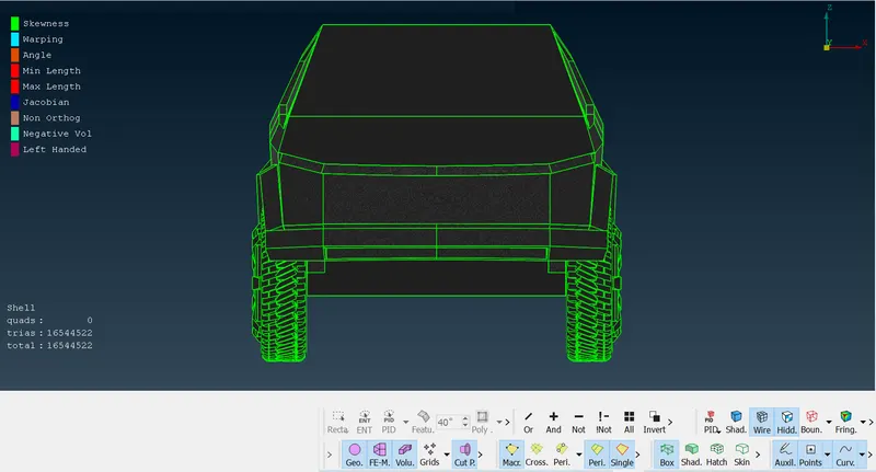
Fig. 2: Tesla cyber truck surface mesh (front-view) for component target length values as specified in Table 1 with number of "Off" elements as 0
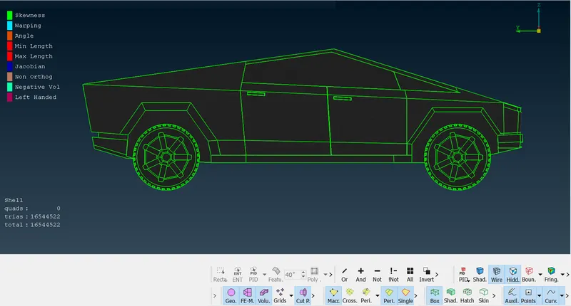
Fig. 3: Tesla cyber truck surface mesh (side-view) for component target length values as specified in Table 1 with number of "Off" elements as 0
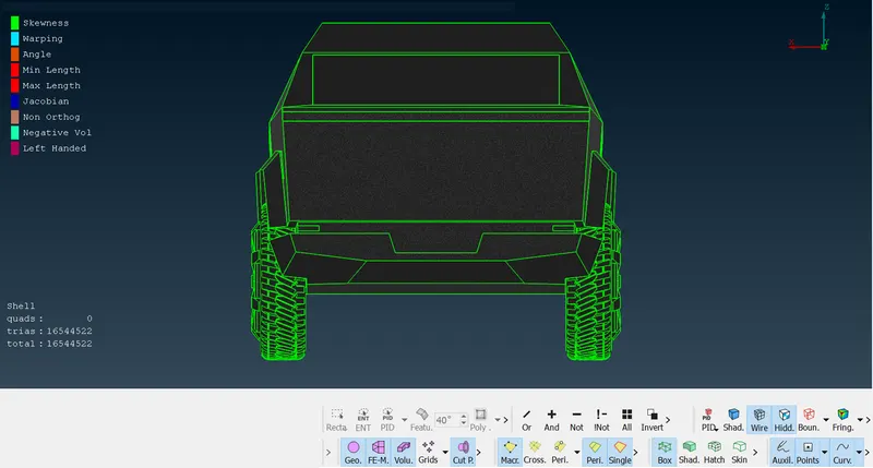
Fig. 4: Tesla cyber truck surface mesh (rear-view) for component target length values as specified in Table 1 with number of "Off" elements as 0
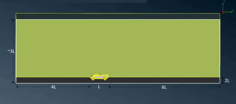
Fig. 5: Wind Tunnel definition with respect to Tesla cyber truck model observed along the side view
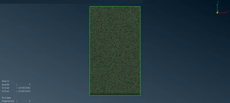
Fig. 6: Tesla cyber truck model and wind tunnel surface mesh (front-view)
4. Learning Outcomes
The learning outcomes from this challenge can be outlined as follows:
- Identification of overlapping and missing features, and errors in geometry using "Geometry Checks", and deletion and/or construction or re-construction of the same using different modules buttons under "Topo" section as part of the Topology cleanup operation.
- Assignment of PIDs through appropriate collection of surfaces belonging to the concerned body offering better control on meshing requirements as well as providing the benefit of re-using them at the time of defining boundary conditions.
- Use of "Init" functionality as a best practice method before defining meshing parameters.
- Setting of different parameters under various button functionalities such as "Auto CFD", "Mesh Parameters" and "Quality Criteria" to set minimum and maximum target length values of elements and the element type.
- Creation of surface mesh using the "Select" and "Visible" sub-options within the "CFD" functionality.
- Definition of wind tunnel domain with respect to the vehicle model as reference and its subsequent surface mesh that transitions with smaller element sizes from the area of interest to larger element sizes using the appropriate biasing feature.
- Distinguishing the volume entity between the wind tunnel domain and the vehicle model.
5. Conclusion
The surface meshing and preparation of volumetric mesh of the given Tesla cyber truck model and its components, including the wind tunnel domain, using different button functionalities was well understood in ANSA-CFD. It was realised that a surface mesh described on the values of minimum and maximum target length with element type as Tria was possible to be created while also ensuring that the number of "Off" elements describing failure in terms of concerned quality criteria parameters across the surface was minimised to 0 and that the same model could be further refined and/or updated depending on the governing boundary and operating conditions of the concerned fluid flow application.