Week 5 Challenge : Surface wrap on Automotive Assembly
1. Aim
The aim of this challenge was to perform surface wrapping on an automotive assembly, in this case a powertrain, based on pre-determined entities, such as given constant target length value using element type as Tria, in ANSA-CFD.
2. Procedure
The approach adopted towards performing surface wrapping on the given automotive assembly in ANSA-CFD involved the following steps:
- Import the given 'Engine' model from the concerned directory containing the ".ansa" file extension using the "Open" option under the "File" menu. This model is selected first as it contains major source of geometrical errors and surfaces that need to deleted as they were not required with respect to carrying out the surface wrap operation.
- After the model is loaded and appears in the "workspace", the "TOPO" module responsible for geometry creation, manipulation and clean up needs to be enabled.
- Before performing any surface creation or deletion operations, it was decided to make use of the "Topo" button under the list of "Faces" button functionalities to automatically create the necessary topological conditions between adjacent CONS on the entire model. The model contained many "ring-shaped" and overlapping features as single objects that were probably utilised to create fillets and rounded area definitions which were unnecessary for surface wrapping and hence deleted starting from the exterior parts before leading into the model and towards the interior components. Once, these objects were removed, a number errors in the form of "Single CONS", "Triple CONS" and few missing and overlapping surfaces was revealed during the "Geometry Checks" which were dealt with in the next two steps.
- New surfaces were defined by accessing the "New" button under the list of "Faces" button functionalities that consisted of different options or algorithms to essentially define the missing face/surface such as "COONS" which makes use of an interpolation principle based on selected boundary curves, "EXISTING SURF" for drawing a new face on an existing surface, "PLANAR" for a planar face (as the name suggests) and "FITTED" for a non-planar face with regards to the selected boundaries. All of the above alternatives, except for "EXISTING SURF", were made use of depending on the characteristics of the missing faces along with the "LOOP" option enabled in certain cases as it was able to predict the list of edges, perimeters or curves forming a close loop thereby saving effort and time. Alternatively, the "Fill Hole" button under the list of "CONS" button functionalities was also implemented to create surfaces between the outlined Single CONS. There were a few surfaces where the "New" or the "Fill Hole" button functionalities could not be implemented directly as the detected surfaces using the previously mentioned algorithms did not close the required surfaces satisfactorily, and in those cases "Hot Points" were inserted on the "CONS" using the "Project" button under the list of "Hot Points" button functionalities to define a new Node or Hot Point. Another button by the name "Intersect" under the list of "Faces" button functionalities was executed to define the intersection between two groups of faces that penetrated each other, in this case at an angle, and consequently to specify a closed area between them, followed by the unnecessary surfaces being deleted using the "Delete" button of the Geometry Group. Also, "Extend" button under the list of "Surfaces" button functionalities were investigated, where necessary, to project one surface onto another in order to fill the necessary gap as was also the objective in terms of closing the model.
- The above "step 4." ensured that all the overlapping and missing surfaces, including "Single Cons" errors, were well taken care of but there were also a number of "Triple Cons" errors present in the model which was revealed when the "Geometry Checks" was performed again, and surfaces that shared a mutual boundary but would still form a closed region was accordingly removed using the "Delete" button of the Geometry Group.
- At this stage and for the given model, no further geometry associated operations were required, as was also confirmed by executing another "Geometry Checks" except for "Triple Cons" defining the shared edges between different parts. The model was saved as a topologically clean model and "step 1." to "step 5." was repeated for the 'Transmission' and 'Gearbox' models, one at a time.
- A new file was opened in ANSA using the "New" option under the "File" menu to integrate each of these three models as part of constituting the powertrain assembly and to arrange them in the required manner, the "Merge" option under the same menu was chosen to select the 'Engine', 'Transmission' and 'Gearbox' models successively while ensuring in the 'Merge Parameters' window, at each instant, the settings were retained for 'Model action' as 'Merge model with current model', under 'Offsets and conflicts resolution' section, 'Nodes', 'Properties', 'Materials', 'Sets', 'Coords', 'Bc sets' as 'offset', and 'Merge Parts' checkbox enabled respectively.
- Surface wrapping can be defined as the creation of a watertight surface mesh around a given assembly consisting of FEM and/or macros. In order to create a surface wrap around the given assembly, it was required that surfaces identified as 'holes', 'intersections' and/or 'gaps' were essentially closed to avoid creation of unnecessary or defeatured regions within the model for which "step 4." was repeated throughout the given assembly. Additionally, the "Compress" utility button was utilised to ensure that all other entities such as grid points, coordinate systems, properties and materials that were defined but not utilised to define the model were no longer present or part of the current deck.
- Surface wrap and the associated operations were defined within the "MESH" module which for ANSA-CFD contains also contains buttons for surface and volume meshing within the same section. To create a surface wrap, the "Wrap" button under the list of "Elements" button functionalities was clicked on followed by choosing the "Constant Length" algorithm which is a high-speed execution code to form a watertight triangular surface mesh of consistent size from an assembly consisting of unconnected and intersecting parts. This was followed by double-clicking on the "Empty" status which opens up a new window titled 'Constant Wrap Octree: Edit' in which the 'Untitled' value under 'Parameters' heading is further double-clicked on and a target length value under the 'Castelation' tab was entered, in this case being 3 mm, while the parameters within the 'Mesh' tab were retained at their default values i.e., 'Shell Type' as 'Trias', 'Wrap mode' as 'Nodes out of structure' and 'Property assignment' as 'Assign properties from structure' to maintain the existing PIDs definitions, followed by clicking on 'OK'. On returning back to the 'Constant Wrap Octree: Edit' window, '0' under 'Contents' section is double-clicked on followed by selecting the PIDs that now exist on the deck and migrating them to the 'Items in Octree Scenario' section and then clicking on 'OK' button to confirm the selections. Generation of surface wrap is now performed by clicking on the 'Run' button in the 'Constant Wrap Octree: Edit' window and depending on the computing system, the process can take a while to complete the required operation. On closing the 'Constant Wrap Octree: Edit' window, the status in the 'CONSTANT WRAP OCTREE' window now highlights "Ready" indicating that the surface wrap operation was performed successfully.
3. Results
Fig. 1, Fig. 2 and Fig. 3 represents the engine, transmission and gear box models after Topology cleanup along different views while Fig. 4 and Fig. 5 indicates the powertrain assembly after surface treatments to deal with 'holes', 'intersections' and/or 'gaps', and surface wrap of the same using the constant length algorithm respectively along different views. It can be observed that the element type across the model is "Tria" for the surface wrapping and on using the "Measure" tool with option set to "Nodes", it was found out that the average distance between two nodal points across different PID surfaces was representing the given target length value approximately.
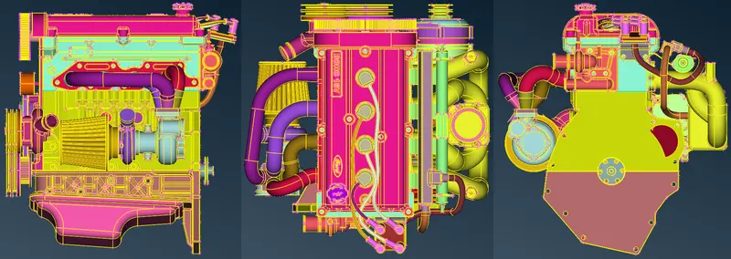
Fig. 1: Engine model after topology cleanup along different views
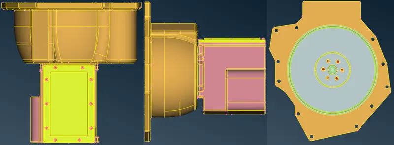
Fig. 2: Transmission model after topology cleanup along different views
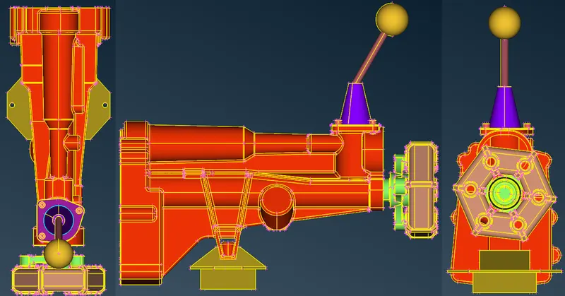
Fig. 3: Gear Box model after topology cleanup along different views
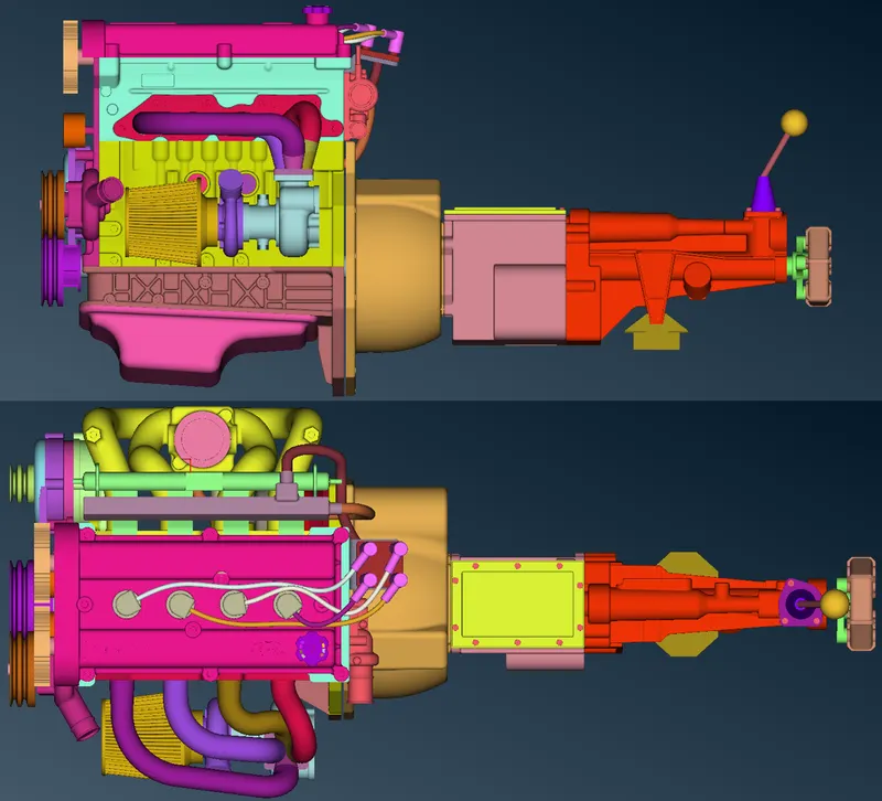
Fig. 4: Powertrain assembly after appropriate surface treatments of 'holes', 'intersections' and/or 'gaps'
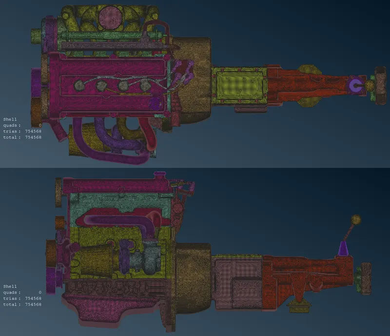
Fig. 5: Powertrain assembly after surface wrap using the constant length algorithm for a target length value of 3mm
4. Learning Outcomes
The learning outcomes from this challenge can be outlined as follows:
- Identification of overlapping and missing features, and errors in geometry using "Geometry Checks", and deletion and/or construction or re-construction of the same using different modules buttons under "Topo" section as part of the Topology cleanup operation.
- Merging of individual components, in a specific order, within a new file interface and closure of 'holes', 'gaps' and/or clean-up operations on 'intersections' to prepare the assembled model for surface wrap.
- Using "Compress" utility function to reduce PIDs that were defined but are no longer present or part of the deck and performing surface wrapping using the constant length algorithm to construct a watertight triangular surface mesh of consistent size on the given assembly.
5. Conclusion
The surface wrapping on the given powertrain automotive assembly using different button functionalities was well understood using ANSA-CFD. It was realised that a surface wrap using constant length algorithm and described on the value of provided target length with element type as Tria was possible to be created while ensuring appropriate surface treatment for 'holes', 'gaps' and/or 'intersections' and that the same model could be further refined and/or updated depending on the governing boundary and operating conditions of the concerned fluid flow application.