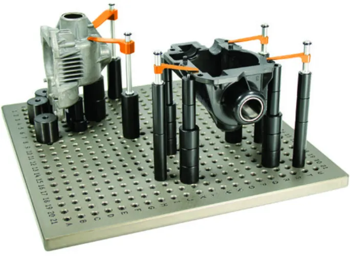
Week 1:- Introduction to BiW and Fixtures Challenge
Introduction to BiW and Fixtures Challenge
1.What is BIW & define its parts?
BIW (Body in White) refers to the welded sheet metal components which form the vehicle structure to which the other components will be married, i.e., chassis, exterior trim, interior trim, & engine. Here the structure is unpainted.
The BIW is still called white even though most of them are grey because in the early year, car shells were kept in white before assembling and it is kept white to give a color choice to customers.
Today’s automobile sector aims to decrease the weight of vehicles and increase the efficiency of vehicles so therefore most of the BIW nowadays are made up of aluminum and composite materials and steel is still used but it has lost its dominant market share due to weight restrictions.
Types of BIW construction:
1. Monocoque construction:
Monocoque body construction integrates the body and chassis of a vehicle into a one-piece structure. Automobile using monocoque construction: - 1962 Lotus 25 Formula race car, McLaren MP4-12C, Ferrari 458, Jaguar XJR-15, McLaren 720s, Bugatti Chiron, etc.
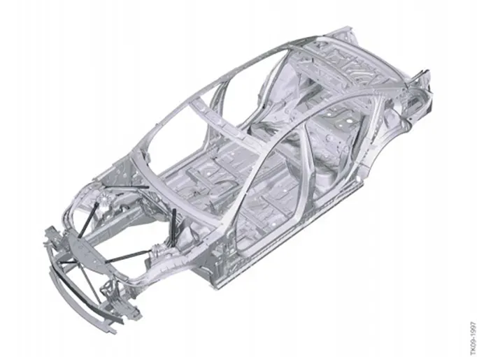
Advantages: Weight reduction, Increased internal space. Aerodynamic, Improved safety, Increased rigidity
Disadvantages: Increased cost, Complex repairs
2. Semi Monocoque Chassis:
A semi-monocoque chassis is like a monocoque chassis, but it gains some structural strength from conventional means, such as an internal skeleton. This chassis is also lightweight and strong but is not as durable and light as an actual monocoque chassis. Automobiles using semi-monocoque chassis: - Audi A-series, BMW X-series, and Porsche Cayenne
3. Body-on-frame construction:
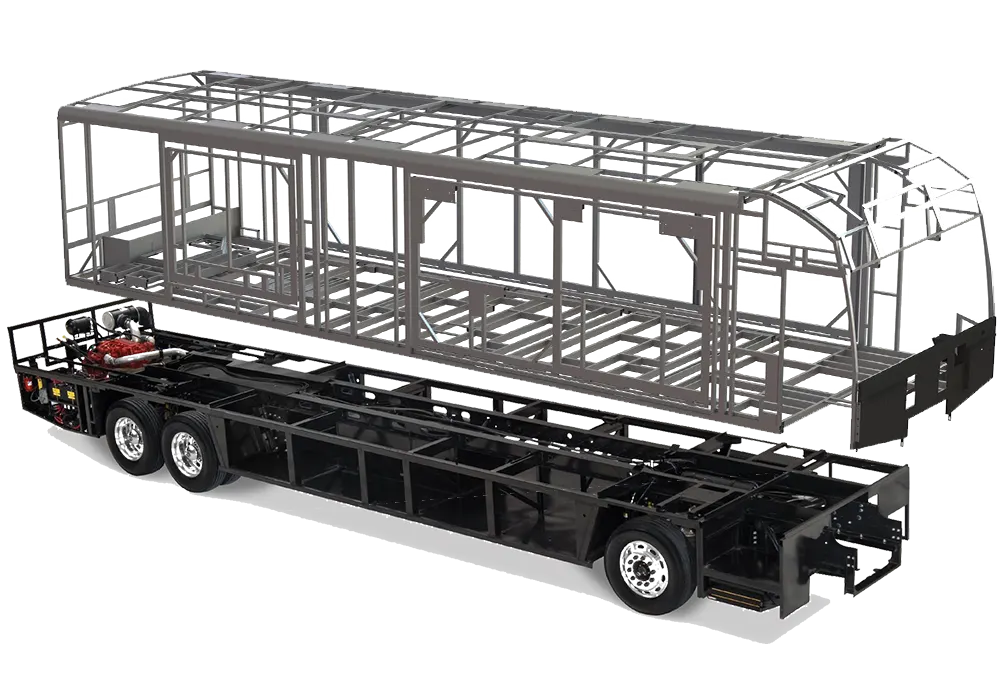
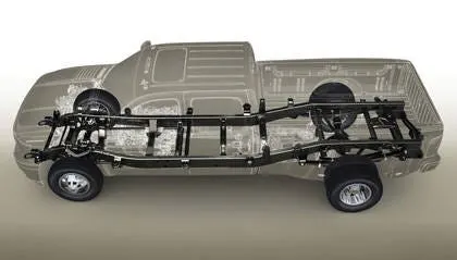
Body-on-frame construction consists of two major components, a rigid ladder-like frame network that carries the engine and drivetrain and a separate body construction that is mounted on it.
4. Unibody design:
Unibody construction refers to a structural design where the body and chassis are integrated into a single unit, but the structure relies on additional internal reinforcements, such as subframes, braces, and pillars, to share and distribute the loads.
In a unibody construction, the body panels and other structural components work together with these internal reinforcements to provide the overall strength and rigidity of the vehicle. In simpler terms, the key difference lies in the level of load-bearing responsibility placed on the external body panels. Monocoque construction primarily relies on the external skin for structural integrity, whereas unibody construction utilizes a combination of the external skin and internal reinforcements.
Automobiles using unibody design: 1922 Lancia Lambda, 1934 Chrysler Airflow, Land Rover Defender, Hyundai Santa Cruz
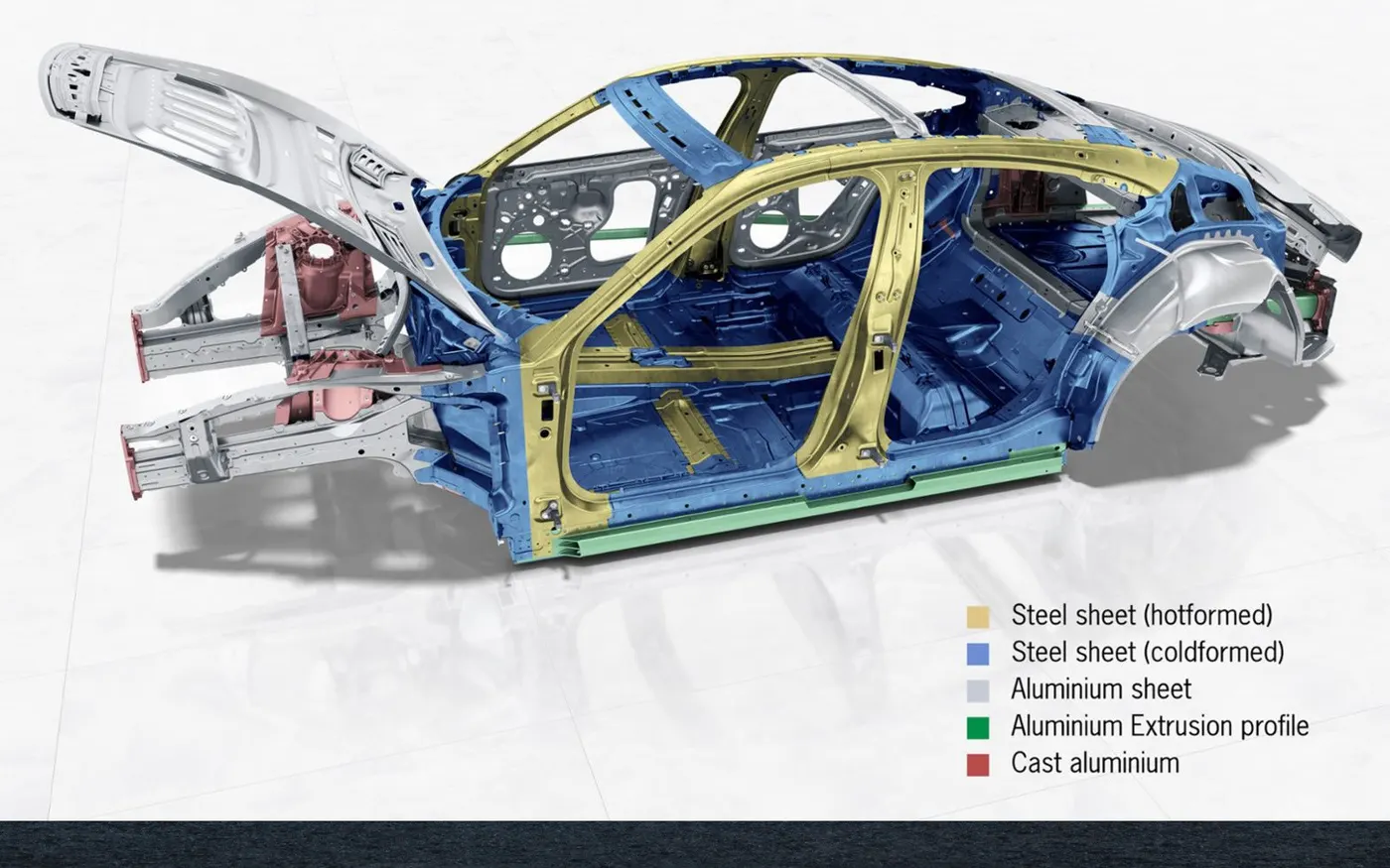
5. Space-frame design:
Space frame vehicle construction, also known as space frame chassis or space frame design, is a structural approach that utilizes a lightweight and rigid framework to support the vehicle's body and mechanical components. It involves constructing a skeletal framework using interconnected beams, tubes, or other structural elements to create a strong and efficient structure.
Automobiles using space frame design: - 1946 Cisitalia D6, 1959 Maserati Tipo 61, Audi R8, Ferrari 360, Lamborghini Gallardo, Mercedes-Benz SLS AMG
Audi R8 Spaceframe
BIW components can be categorized into five categories:
1. Body Sides
- A-pillar: frontmost support to the roof.
- B-pillar: second support to the roof
- C/D pillar: C- is the rearmost support to the roof in case of a two-row seating system, it will third one. D- is the fourth support, usually the rear side of the quarter panel.
- Ring Panel: a structure panel connecting the rear and front portion.
- Quarter Panel: rearmost panel of a body side structure
- Drip rails/Gutter: an exposed channel applied to the roof over the side windows to direct water away from the windows
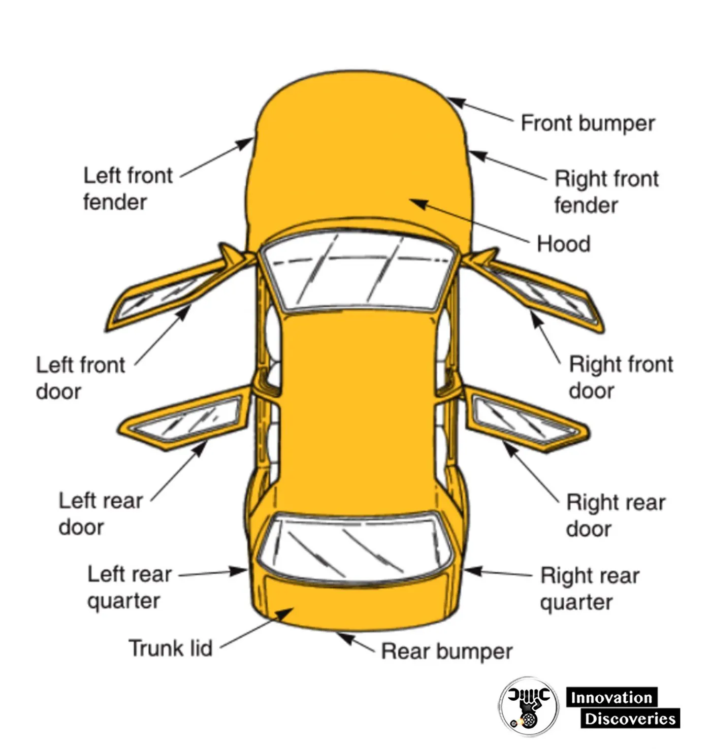
2. Underbody
- Dash panel: provides partition b/w engine and the driver cabin.
- FRT floor provides a base for seats
- Raiser: connects front floor to rear floor by providing the level difference
- Rear floor: floor on the rear of the car and provides partition from ground and base for rear seats.
- Rear wheelhouse
3. Closures
- Front door
- Rear door
- Hood
- Decklid
4. Roof
- Roof
- Header: structural member above the windshield at the juncture with the forward edge of the roof panel
- Bows

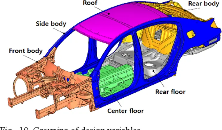
5. Front End Structure
- Plenum Panel: a chamber located b/w the throttle body and runner of the intake manifold.
- FRT wheelhouse (Fender): is an encasement around the wheel.
- Wing Panel: outermost side panel in the front
- Cowl: portion of the body bounded by the front fenders, the base of the windshield, and the rear edge of the hood.
- Upper tie bar: upper panel in the front connecting the two sides of the front structure.
- Lower tie bar: lower panel in front connecting the two sides of the front structure.
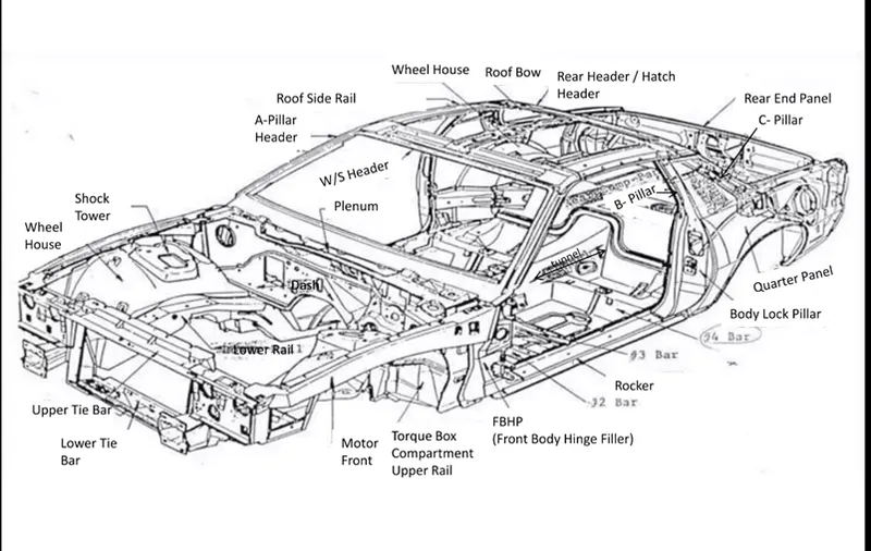
2. What do you understand by BIW nomenclature?
BIW Nomenclature refers to the identification and labelling system used for various components and assemblies in the body shop during the production of a vehicle's body structure. It is a standardized system that helps track and manage the multitude of parts involved in the assembly of the BIW.
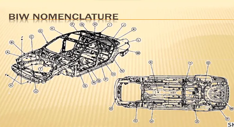
|
Items |
UK Description |
US Description |
|
A |
Inner Wing Panel |
Motor Compartment Side Panel |
|
B |
Upper Wing Member |
Motor Compartment Upper Rail |
|
C |
Suspension tower |
Shock tower |
|
D |
Upper ‘A’ Pillar |
‘A’ – Pillar or Windshield Pillar |
|
E |
Windscreen header rail |
Windshield header or front header |
|
F |
Roof Stiffener |
Roof bow |
|
G |
Rear Parcel tray |
Package shelf |
|
H |
Contrail |
Side roof rail |
|
I |
Backlight frame |
Backlite header or Rear header |
|
J |
‘C’ - Pillar |
‘C’ – Pillar |
|
K |
‘D’ - Pillar |
‘D’ - Pillar |
|
L |
Rear Quarter Panel |
Rear Quarter Panel |
|
M |
Boot Floor Panel |
Rear Compartment Pan |
|
N |
Rear Seatback Ring |
Rear Seatback Opening Frame |
|
O |
Rear Seat Panel |
Rear Seatback panel |
|
P |
‘B’- Pillar |
‘B’- Pillar or Centre Pillar |
|
Q |
Floor Panel |
Floor Pan |
|
R |
Sill |
Rocker or Rocker Panel |
|
S |
Lower ‘A’-Pillar |
Front body hinge pillar (FBHP) |
|
T |
Dash Panel |
Dash Panel |
|
U |
Engine (longitudinal) rail |
Motor Compartment Lower Rail |
|
V |
Front Bumper |
Front Bumper |
|
W |
Spare Wheel Well |
Spare Tire Well |
|
X |
Centre (Longitudinal) Tunnel |
Tunnel |
|
Y |
Rear Seat Crossbeam |
# 4 Crossbar |
|
Z |
Rear Suspension Support Beam |
# 5 Crossbar |
- The terms are standard but they differ in some countries.
- As automotive industries spread worldwide, the terms and standards will be different for similar components.
- For example, One component of BIW is known as inner wing panel in the UK description another side the same component of BIW is known as the Motor compartment side panel in the US description.
3. What is fixture & its types?
A device that is used to hold, locate and support the component in the manufacturing industry is called a fixture. Fixtures ensure to provide the stability to the part when any process is being done on that part. That process can be welding, riveting, grinding, drilling, etc. In BIW fixture design Fixture works on the 3-2-1 principle.
There are three types of BIW fixture processes that are used in companies.
- Pre Production Fixture
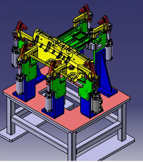
These kinds of fixtures are made commonly for the prototype stage, where they check the productivity and feasibility of the fixture. these fixtures require a lot of studies and detailing because it is at the preproduction stage. if
a new standard or a process is needed, they first modify the preproduction fixture and upgrade to the production fixture at the assembly line.
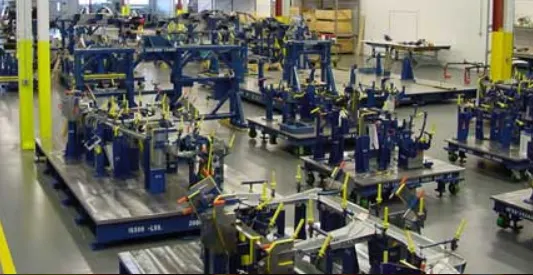
- Production Fixture
These kinds of fixtures are used in the main production line or mass production departments in a company. for example, the assembly line is where all the sheet metal BIW parts are joined or welded together so a production fixture is used to check the geometries and fast production in less time.
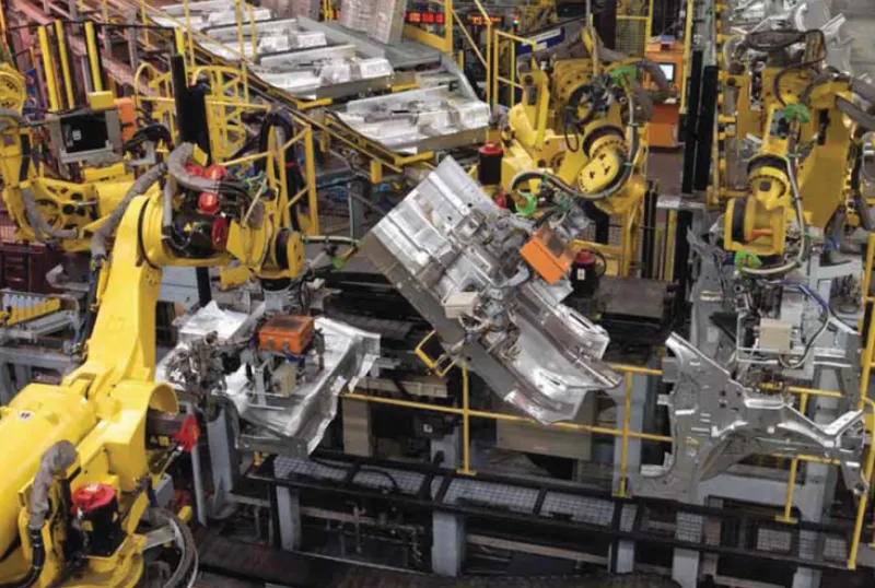
- Checking Fixture
These types of fixtures are used to inspect the produced BIW sheet metal. to check the tolerances, Geometries, dimensions, etc. For fixing the Parts they actually use gauges to inspect and get a great accuracy while checking.
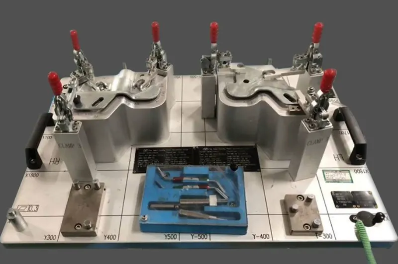
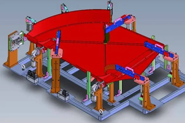
There are sub-units that make a fixture.
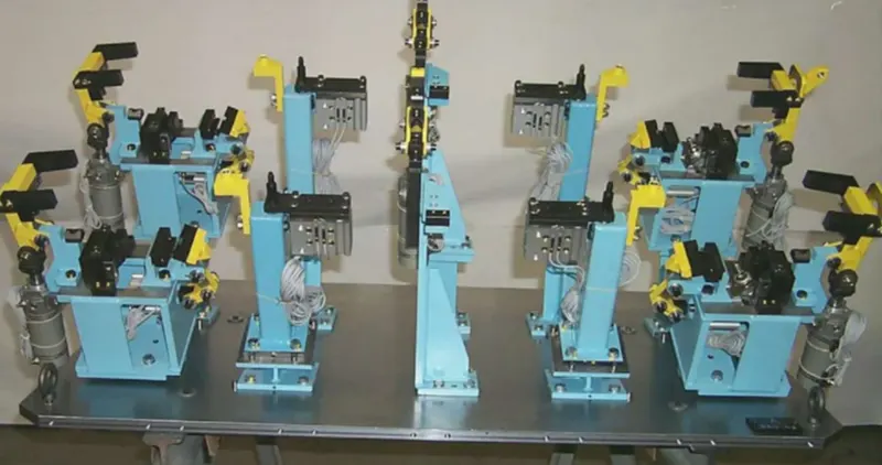
-Clamp units.
clamps hold the car part firmly and prevent the part from distortion while carrying out the spot welding operation. some of the clamps are,
L- Block, Shim, and Spacer, Blade spacer, Riser, etc.
- Pin units
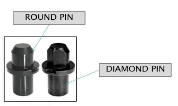
the locating pins are used to locate a body part in a position sufficiently accurate to execute a welding process. Usually, two locating pins are enough to properly locate the body part on one plane. one of the pins is round, and another one is diamond-shaped. This configuration will allow the easier loading of body parts.
- Rest units
These units are used to rest the panel
- Standard parts
these parts are used and also available in the market for purchases. with the help of standard parts, the designing of other fixtures is easy. some of the standard parts are
suction cups, cylinders, etc.
4. What is the basic principle of fixture design?
The principle of Fixture Design is the 3-2-1 Principle.
For a fixture designer, the major portion of design time is spent deciding how to locate the work piece in the fixture.
For any free body there are total of twelve degrees of freedom as below:
6 translational degrees of freedom: +X, -X, + Y, -Y, +Z, -Z
And six rotational degrees of freedom:
- Clockwise around X axis (CROT-X)
- Anticlockwise around X axis (ACROT-X)
- Clockwise around Y axis (CROT-Y)
- Anticlockwise around Y axis (ACROT-Y)
- Clockwise around Z axis (CROT-Z)
- Anticlockwise around Z axis (ACROT-Z)
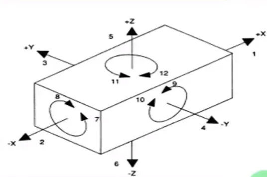
You must fix all the 12 degrees of freedom in order to locate the work piece in the fixture. So, 12 degrees of freedom of the work piece need to be fixed & thus we can achieve zero degree of freedom for the work piece.
A workpiece will be completely confined when blanked against:
- 3 points in one plane: The “3” in 3-2-1 refers to 3 locators (passive fixture elements) on the primary locating/datum surface.
- 2 points in another plane: The “2” in 3-2-1 refers to 2 locators on the secondary locating/datum surface.
- 1 point in a third plane: The “1” in 3-2-1 refers to 1 locator on the tertiary locating/datum surface
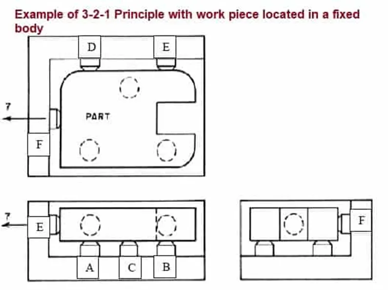
The location arrangement depends on the type of operation, degrees of required accuracy.
- Flat locators: These are used for the location of the flat machined surfaces of a component.
- Cylindrical locators: These are used for the location of components with drilled holes.
- Conical locators: These locators are used to support the workpieces with cylindrical holes.
- Jack pin locators: These locators support rough workpieces.
- Drill bush locators: These locators hold and locate the cylindrical workpieces.
- Vee locators: These locators hold circular and semi-circular workpieces.
5. Elaborate types of BIW Stations?
BIW stations are specific workstations or areas within the automotive manufacturing process where the body structure of a vehicle is assembled.
The assembly line is where the different types of panels are joined together in each specified zone. Each panel categories will have individual zones, as underbody zone, Door’s zone, Hood zone etc.,
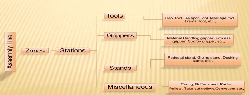
Each zone is comprised of several stations:
1. Tool
A tool is a fixture which consists of a number of units together to hold a car part in general.
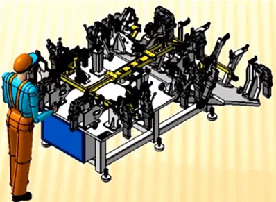
- Geo Tools: A geo tool is a fixture in which the geometry of the panels which are welded together is defined accurately. The pin tolerance for a geo pin will be of closer tolerance i.e. - 0.15 in general.
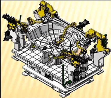
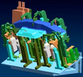
- Re-Spot Tools: A re-spot tool is a fixture in which the remaining weld spots which are not achieved in geo tool are welded for the pre welded panel from the geo tool. The pin tolerance for a re-spot pin will be of tolerance with -0.28 in general.
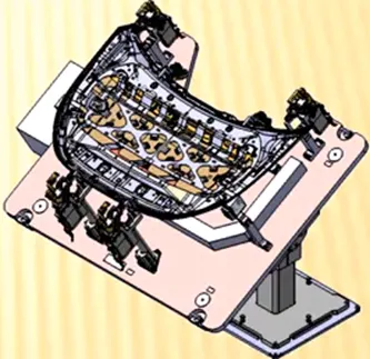
- Hemming or Marriage Tool: A marriage or a hemming tool is a fixture in which the inner panel assembly and outer panel assembly are joined together. These are done by welding or by hemming in case of closure panels.
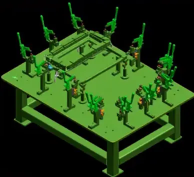
2. Checking Station
A Checking Station tool is a fixture which is used to check the automotive parts or assemblies, ensuring all the coordinates, relative dimensions & positions as per the
tolerances. A checking station can be a gauge type, fixed type and automated checking fixtures.
A Checking gauge is a tool where work piece is held & various measuring gauges are introduced to ensure the dimensions & repeatability.
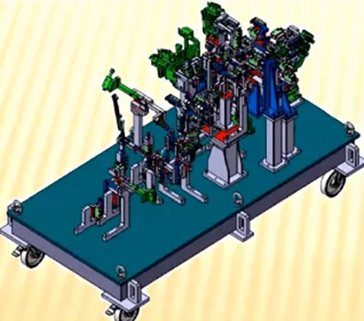
A fixed type checking fixture is used where the work piece is fixed with clamps & pins & a CMM machine is used which measures the coordinates of different points of the panel or assembly, compares it with the nominal values & gives a report.
3. Gripper
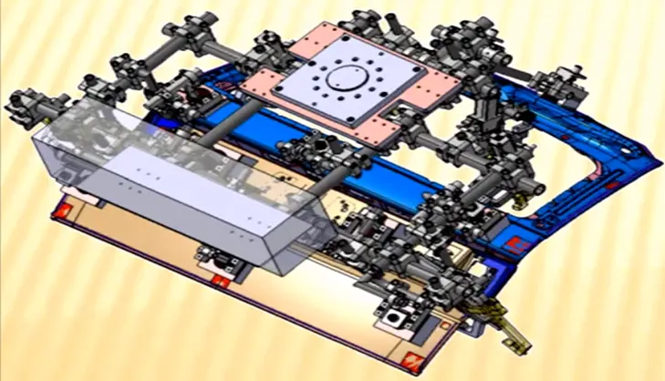
A Gripper is a device or a fixture which holds the car panel and is fixed to the manipulating end of a robot or an end effector. Also known as EOAT — End of Arm Tooling.
- Material Handling Gripper: Material Handling gripper are designed for handling the car panel from one tool (Station) to other tool (Station)
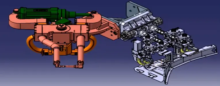
- Process Gripper: Process gripper are designed for handling the car panel from one tool (Station) to other tool (Station), And in addition to that it undergoes process like pedestal welding, pedestal riveting, gluing, sealing, etc.,
- Combo Gripper: Combo gripper are designed for handling the car panel from one tool (Station) to another tool (Station), Also with combination of weld gun at another side of the gripper for welding. For Example: Gripper + Weld Gun
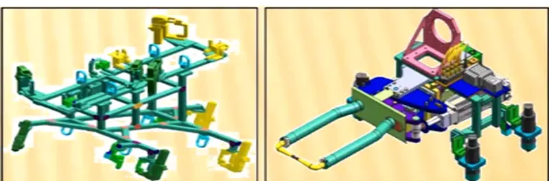
- Dual Gripper: Dual gripper are designed for handling the car panel from one tool (Station) to another tool (Station), With two-sided gripper. For Example: Gripper + Gripper
4. Stands
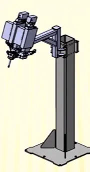
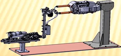
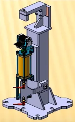
- Pedestal Gun Stand: Weld gun is mounted to a fixed stand which is grouted to the floor permanently, Where the process gripper carries the car panel to weld the spot with this fixed weld gun.
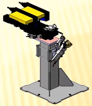
- Gluing and Sealer Stand: Gluing gun or sealer gun is fixed to a welded or a standard stand which is grouted to the floor permanently.
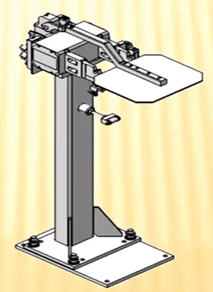
- Docking Stand: When robots are selected for multi-tasking like material handling & welding, which cannot carry both due to some limitations (payload capacity of the robot or space constraint) the robot will drop and pick the gripper or gun after completing the respective operation with the help of Docking stands.
- Date Stamp Stand: The panel will get the date embossed on to it, with the date stamping device mounted on this date stamp stand.
5. Miscellaneous
- Buffer Storage: A buffer storage stand is a storage solution used in manufacturing or assembly processes to temporarily store components, parts, or products during production. It serves as an intermediate storage area between various stages of the production line, allowing for smoother workflow and reducing the risk of bottlenecks or interruptions.
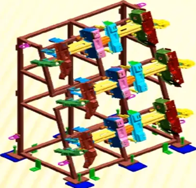
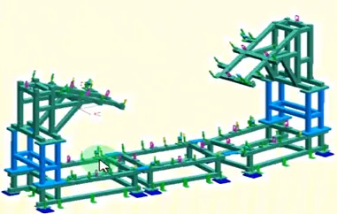
- Rack: Racks refer to specialized structures or frameworks used for organizing, storing, and transporting fixtures.
- Takeout Trolley: Take out trolley is used to take the car panel out of the robotic working cell between the cycle for purpose.
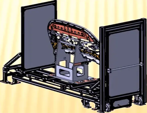
- Conveyor: A conveyor is a material handling system that consists of a continuous belt, chain, or other flexible surface that moves materials from one location to another.
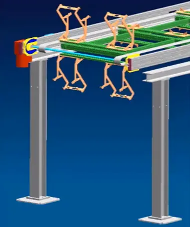
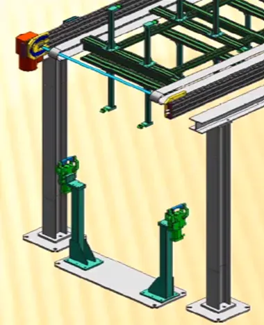
- Curing: In this Station product received after sealing application, is kept idle at ambient temperature, which allows sealant to get dry with better bonding between the panel.
6. What are the basic terminologies used in the BIW fixture?
Some of the basic terminoligies in BIW fixtures are,
1. MYLAR
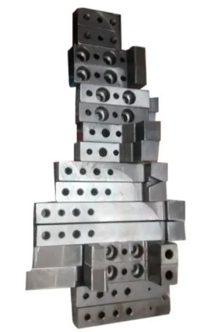
MYLAR is one kind of block that touches the panel and holds or clamps the panel. Mylars are always designed in CAR LINE. Mylar is also called NC(Numerically Controlled)Block. Mylars are mounted on any block or plate with Shimming, So that height of mylar can be adjusted accordingly at the assembly level. For ‘A’ class surfaces Nylon mylars are used. So that surface can be saved from scratches.
2. Pins
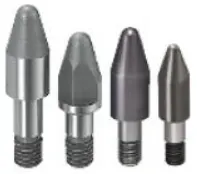
Pins are used to locking the rotational movement of the panel. Generally there two types of Pins, one is Round Pin and another one is a Diamond pin. mostly they use two and three-directional shimming for pins as per the angle of the pin in the carline. In some cases, a collared pin, when the pin is supposed to support the panel as well. For this kind of pin, they provide 3 way shimming irrespective of pin angle to the carline.
3. Blade
The plate which connects Riser to the Clamp cylinder is named Blade. This plate plays an important role in building the unit. The plate can be of any shape.
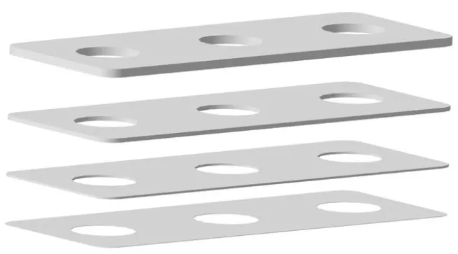
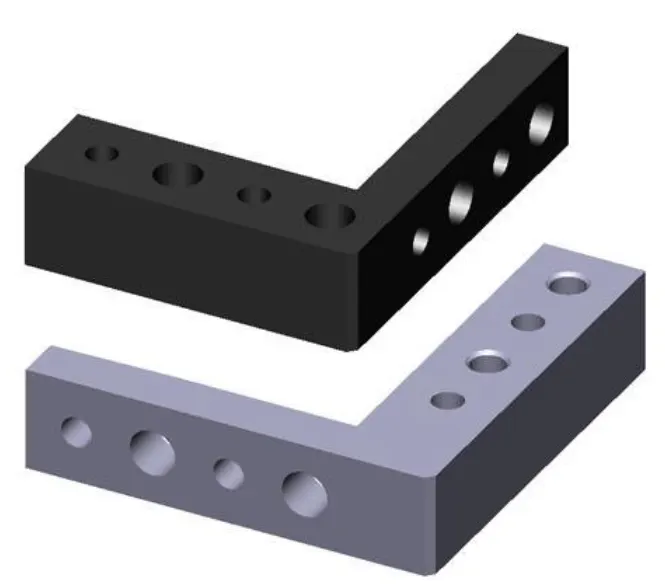
4. L Blocks
A plate shaped as L is called an L block. This part is used as a connection between mylar and Blade. Generally, L blocks are used to provide shimming. It is not necessary that L blocks are only used for shimming, its uses changes as per the requirements, At some places, it is used just to connect one part to another.
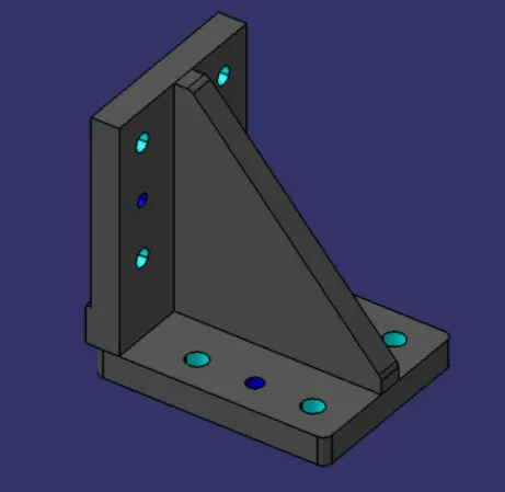
5.Riser
The part which is mounted on the base plate and holds a clamp or pin cylinder on it, is called Riser. Riser can be Standard Part or manufactured part, it varies from project to project. A riser can be a Single part or welded part. Standard risers also have various shapes and sizes.
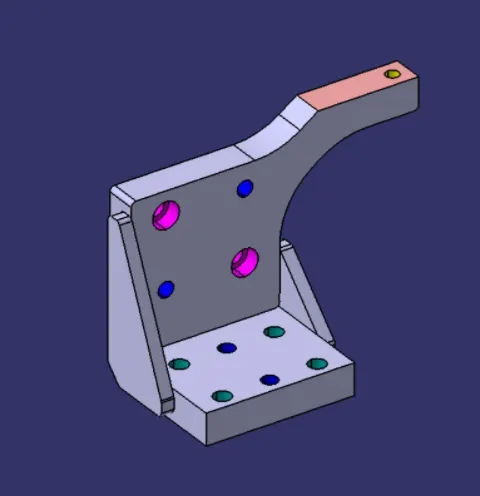
6. Weldment
Weldment is the assembly of two or more parts that are joined by welding. To make a weldment it is the thumb rule to have a 5 mm overlay on each other plates so that space can be provided for welding. A weldment can be of any size and any number of plates.
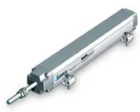
7. Sensors
These are mostly used in checking stations. to check hole dimensions.
8. CMM
A Coordinate Measuring Machine (CMM) is a measuring device to inspect the physical geometry of an object by sensing discrete points on the surface of the object or a part using a sensing probe. When the probe touches a surface, the transducer records the input and sends it as an electric impulse to the computer.