Wiring harness design in CATIA V5 - 3D modeling Week 2 Challenge
Q1. Download following connectors & Connector clip cad data from given link & define it as Electrical Connector using Electrical Part design Workbench. Define all the necessary properties to Connectors & Clip
1.) Step– 1 :- CREATE / DOWNLOAD CONNECTOR 3D
The connectors to be defined electrically, has to be created by using the respective design tool, or the readily available 3D file of the connector in IGS/STP format is available in online sites, from the OEM manufacturer of connectors.
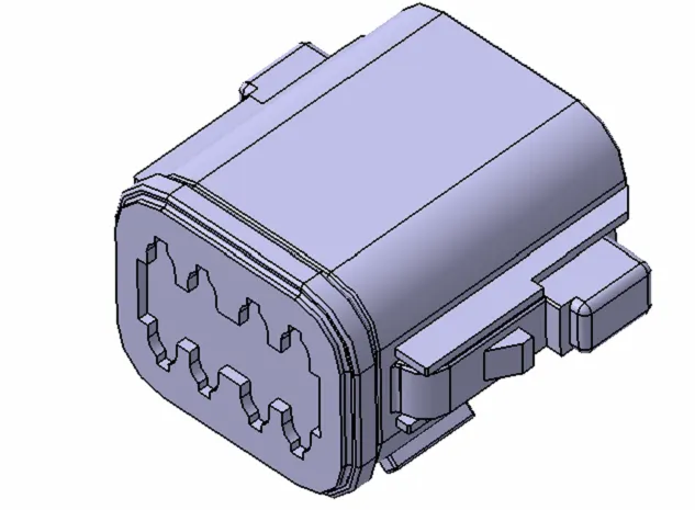
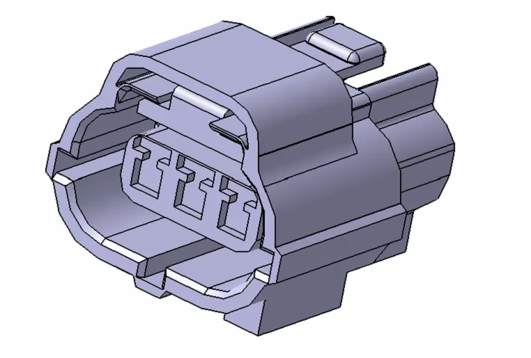
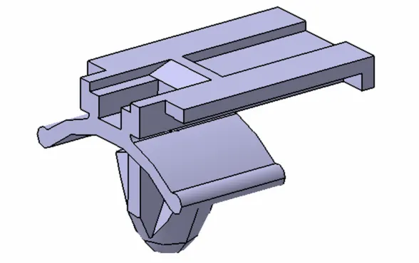
The connectors which are used in the respective challenge for defining has an electrical part is shown below:-
A) MALE CONNECTOR :- Deutsch DT06 – 08SA
B)FEMALE - CONNECTOR :- Tyco 174357-2
C) Tyco 85229-1 (CAVITY CLIP)
2.) Step– 2 :- CREATION OF REQUIRED GEOMETRICAL PARAMETERS
Once the connectors 3D CAD file is downloaded from the respective websites, the connectors are saved in “CATpart” format, in order to save the file in ‘CATALOG folder’ as a storing device in CATIA V5.
The Geometrical parameters created for the connector are shown below,
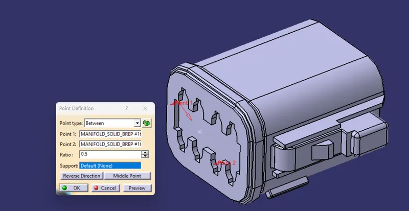
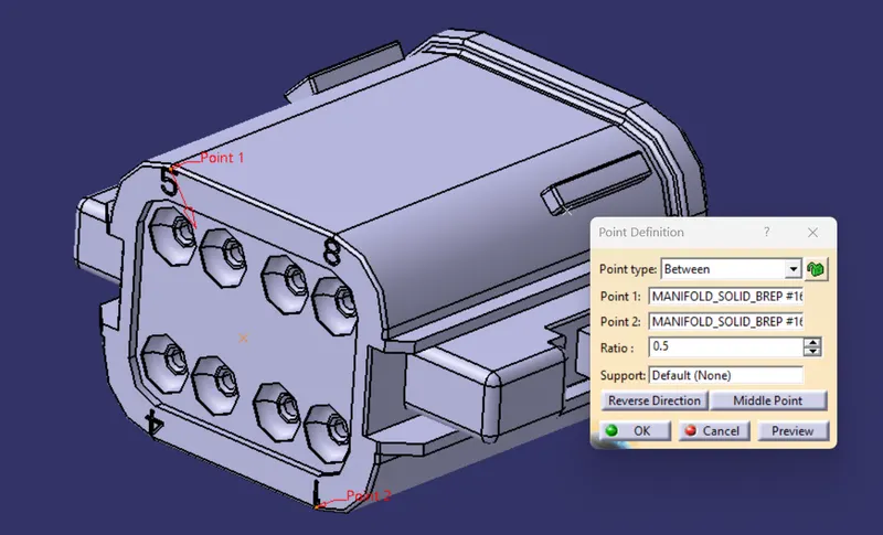
a) Point Definition – Point definition is a command in CATIA, to create points on the 3D CATpart. The Point is defined in the connector, by creating a point in the center of the face of connector, where the mating takes place.
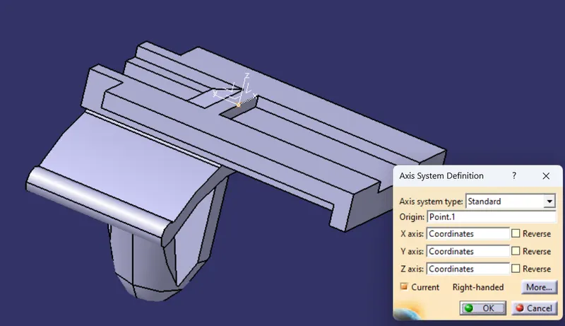
b) Axis System Definition – Axis system definition is a command in CATIA, to create the axis system on the defined point created by ‘point definition’ command.
The axis system is a 3-axis system –
1.) X-AXIS.,
2.) Y-AXIS.,
3.) Z-AXIS.
The three axes are perpendicular to each other, with an angle of 90 degrees between two axes in a 3D space.
A) MALE CONNECTOR :- Deutsch DT06 – 08SA
- POINT DEFINATION
a)CAVITY CONNECTION SIDE
b)BUNDLE ENTRY SIDE
- Axis System Defination
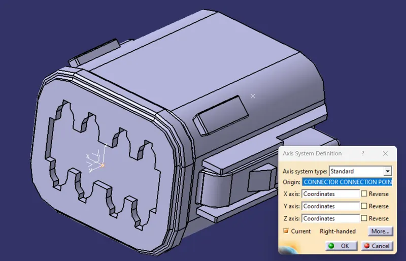
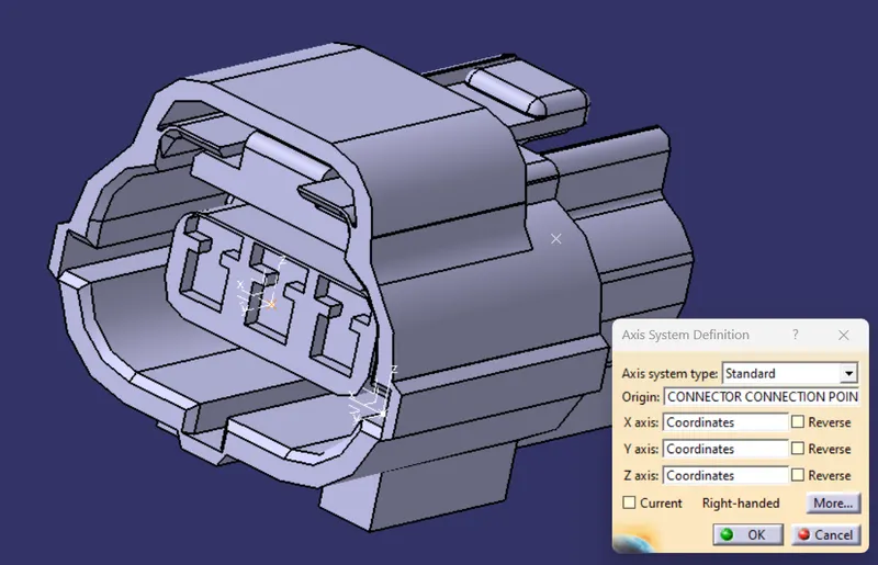
B)FEMALE - CONNECTOR :- Tyco 174357-2
- POINT DEFINATION
a. CONNECTOR CONNECTION POINT
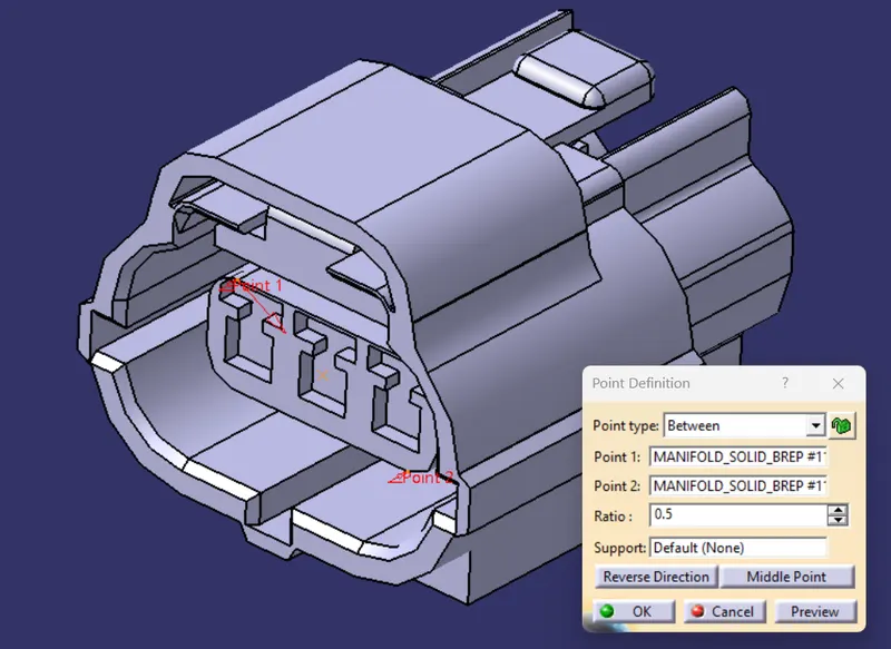
b. BUNDLE ENTRY POINT
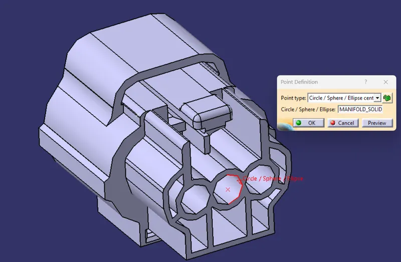
c. CAVITY CONNECTION POINT
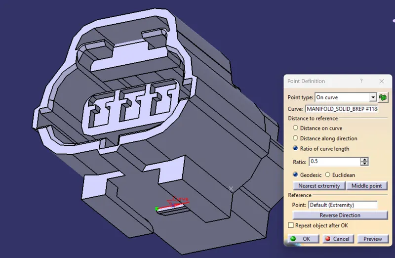
- AXIS SYSTEM DEFINATION
a. CONNECTOR CONNECTION POINT
b. CAVITY CONNECTION POINT
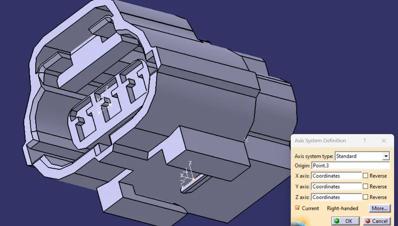
C) Tyco 85229-1 (CAVITY CLIP)
- POINT DEFINATTION
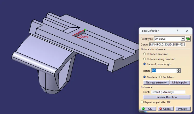
- AXIS SYSTEM DEFINATION
3.) Step – 3 :- DEFINING PART AS CONNECTOR
Once the geometrical parameters are created on the connector part, then the part has to be defined electrically as a connector.
To define the part electrically as a connector, then we have to go to ‘electrical part design workbench’.
as shown in fig:-
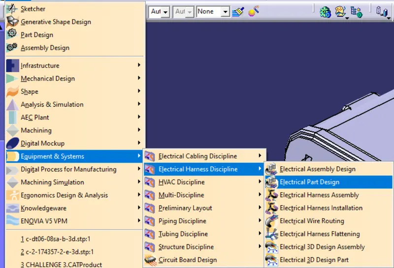
We have to choose the ‘Define connector’ command and select the connector part and the total number of terminations available in the connector should be entered in the ‘Define connector’ dialog box.
The number of termination points are counted on the bundle entry face of the connector.
The connector definition in CATIA for the connectors is shown below,
A) MALE CONNECTOR :- Deutsch DT06 – 08SA
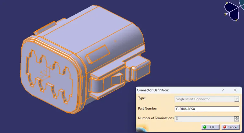
Part is created as Electrical component i.e Connector with 3 terminations.
B)FEMALE - CONNECTOR :- Tyco 174357-2
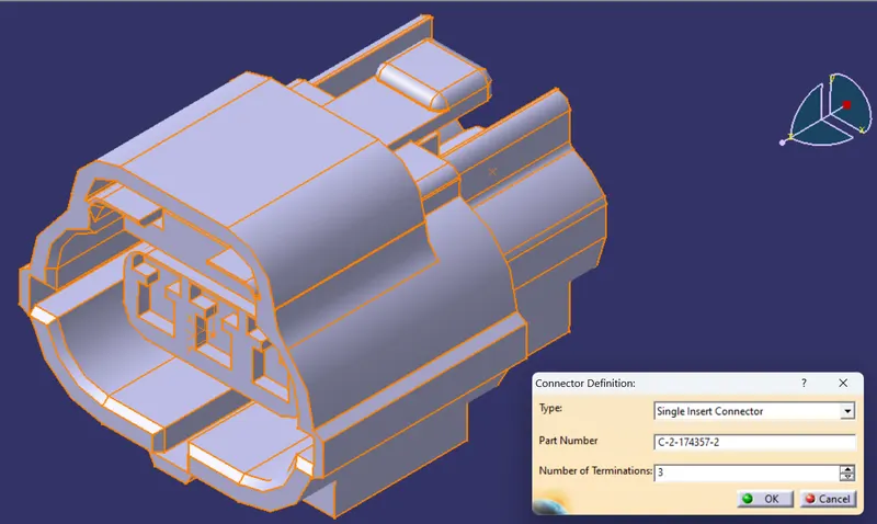
Part is created as Electrical component i.e connector with 8 terminations
4.) Step – 4 :- DEFINING BUNDLE CONNECTION POINT
The defining of the bundle connection point is the next stage after the completion of defining connector part as connector.
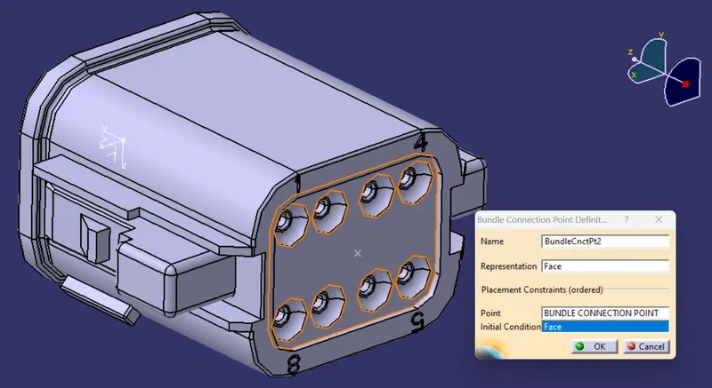
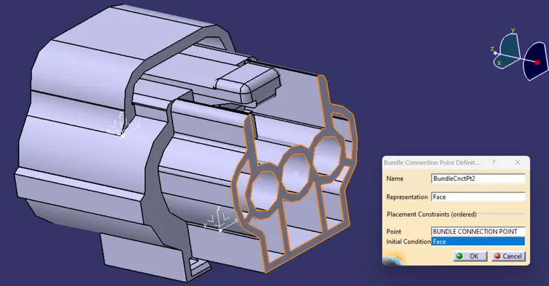
The defining of bundle connection point is to identify the entry connection point of bundle/wires, which will be connecting to the connector. The bundle connection point definition can be achievable only when the connector part is defined as a connector in the previous stage.
In bundle connection point definition dialog box, select the face, where the bundle entry point is placed, followed by selection of bundle entry point and the face where the bundle entry point is placed as the constraints.
The defining of bundle connection point for the connectors are shown below,.
A) MALE CONNECTOR :- Deutsch DT06 – 08SA
B)FEMALE - CONNECTOR :- Tyco 174357-2
5.) Step – 5 :- DEFINING CONNECTOR CONNECTION POINT
The defining of the connector connection point is the next stage after the completion of defining bundle connection point for connector.
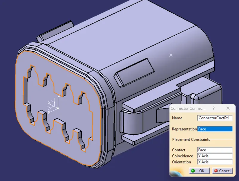
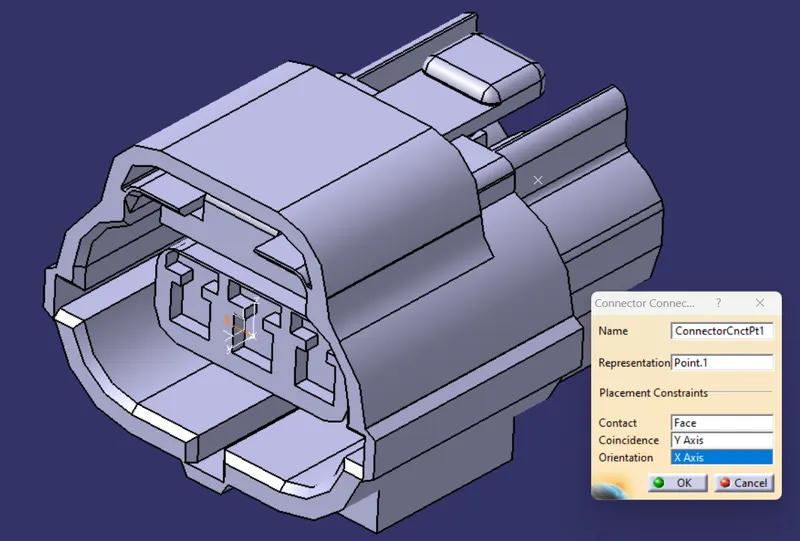
The defining of the connector connection point is to create the mating assembly with the different connector, for transferring the electrical data from one connector to another connector, for completing its function of performing the task. The connector connection point definition dialog box, asks for selecting of point where the connector connection has to be made, followed by selection of face, where the connector connection point is placed.
The Connector connection point has 3 axis system, from which the mating/coincidence axis is to be selected where the mating of connectors takes place, followed by selection of orientation axis.
The connector connection point definition can be achievable only when the bundle connection point is defined in connector as in the previous stage.
The defining of connector connection point for the connectors are shown below,
A) MALE CONNECTOR :- Deutsch DT06 – 08SA
B)FEMALE - CONNECTOR :- Tyco 174357-2
6.) Step– 6 :- DEFINING “CAVITY CONNECTION POINT”
The defining of the cavity connection point is the next stage after the completion of defining connector connection point for connector.
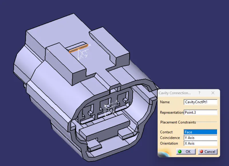
The defining of cavity connection point in connector is for enabling the placement of cavity connector clip in the connector. The defining of cavity connection point is to be done only, if the connector has the provision for placement of cavity connector clip.
The defining of cavity connection point is similar to the defining of connector connection point.
The cavity connection point definition dialog box, asks for selecting of point where the cavity connector clip has to be placed, followed by selection of face, where the cavity connector clip’s face will make contacts.
The cavity connector point has 3 axis system, from which the mating/coincidence axis is to be selected where the contact of cavity connector clip takes place, followed by selection of orientation axis.
The defining of cavity connector connection point for the connector is shown below,
A)FEMALE - CONNECTOR :- Tyco 174357-2
Once the mounting equipment is defined for the cavity connector clip, then the cavity definition is to be done for cavity connector clip.
The cavity definition in cavity connector clip is done by selecting the cavity connection point, followed by selection of the face, where the cavity connector point is placed.
The cavity connector clip point has 3 axis system, from which the mating/coincidence axis is to be selected where the contact of cavity connector clip will make contact in the connector cavity, followed by selection of orientation axis.
The cavity definition for the cavity connector clip is shown below,
B) Tyco 85229-1 (CAVITY CLIP)
- mounting equipment defination
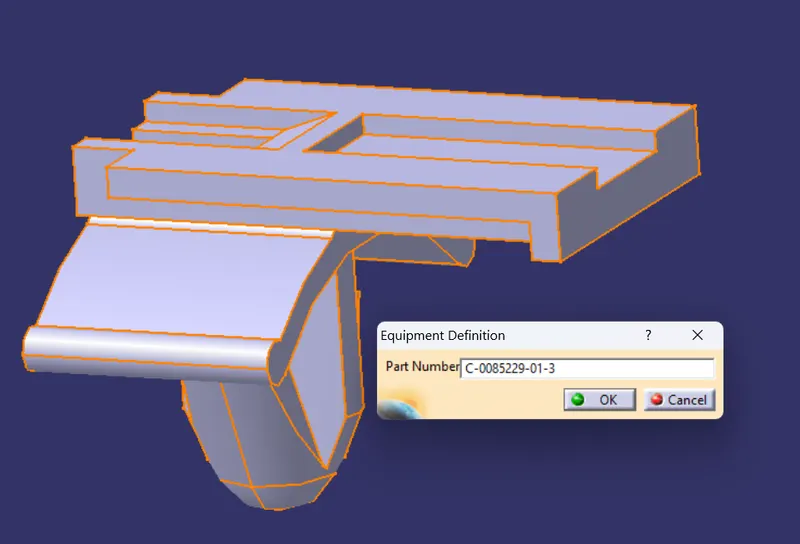
Once the mounting equipment is defined for the cavity connector clip, then the cavity definition is to be done for cavity connector clip.
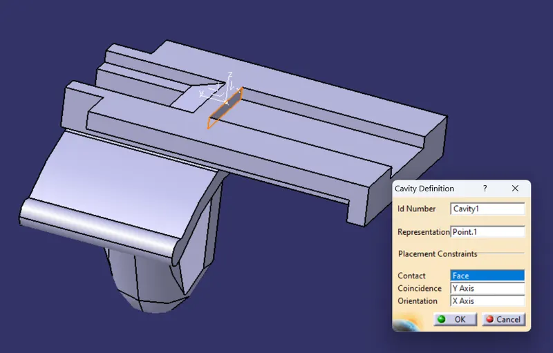
The cavity definition in cavity connector clip is done by selecting the cavity connection point, followed by selection of the face, where the cavity connector point is placed.
The cavity connector clip point has 3 axis system, from which the mating/coincidence axis is to be selected where the contact of cavity connector clip will make contact in the connector cavity, followed by selection of orientation axis.
The cavity definition for the cavity connector clip is shown below,
- cavity defination
Once all the connectors are defined electrically, with all electrical properties, then we can save the connectors by using the “STORE DEVICE” command.
The “STORE DEVICE” command, helps to store the electrically defined connectors in ‘CATALOG’, which is created in CATIA by using ‘Catalog editor’ option available in ‘infrastructure’ tab of ‘options’ settings.
We can create a dedicated catalog for connectors, to save the electrically defined connector, so that, it will be readily available in future in use for creating wiring harness design.
- Electrical assembly design of Tyco 174357-2 (Female connector) and Tyco 85229-1 (Cavity connector clip)
The assembly of cavity connector clip and female connector is performed in ‘Electrical assembly design’ workbench in CATIA.
In the ‘electrical assembly design’ workbench, the cavity connector clip and female connector are added to a new assembly part.
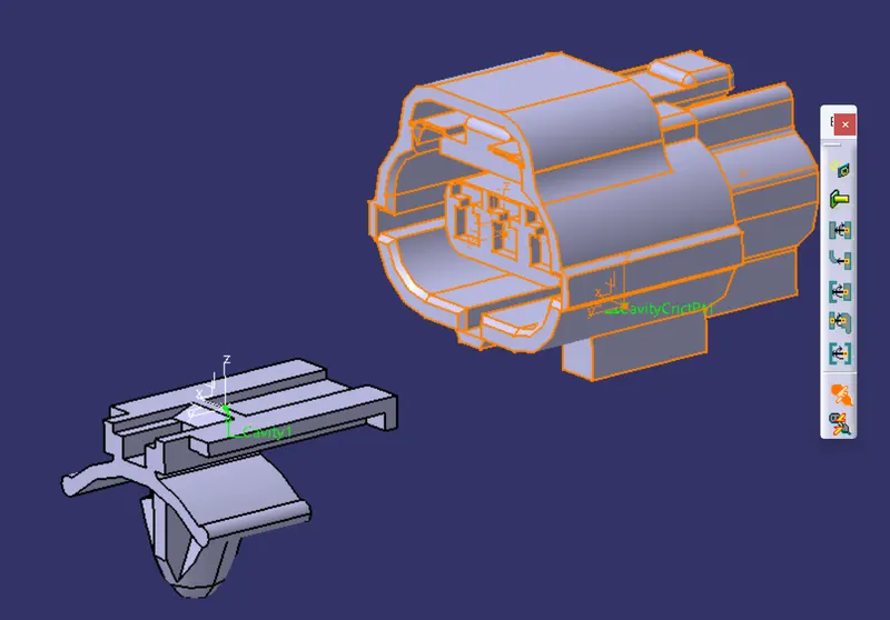
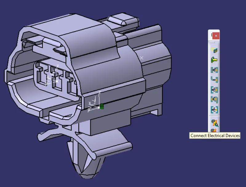
The command “Connect electrical devices” is used to assemble the cavity connector clip with the connector.
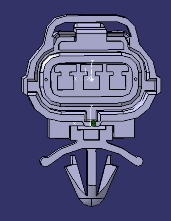
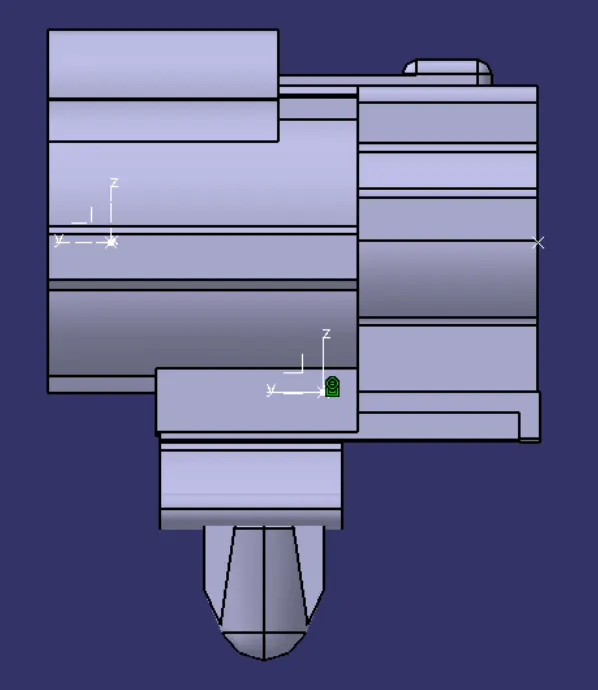
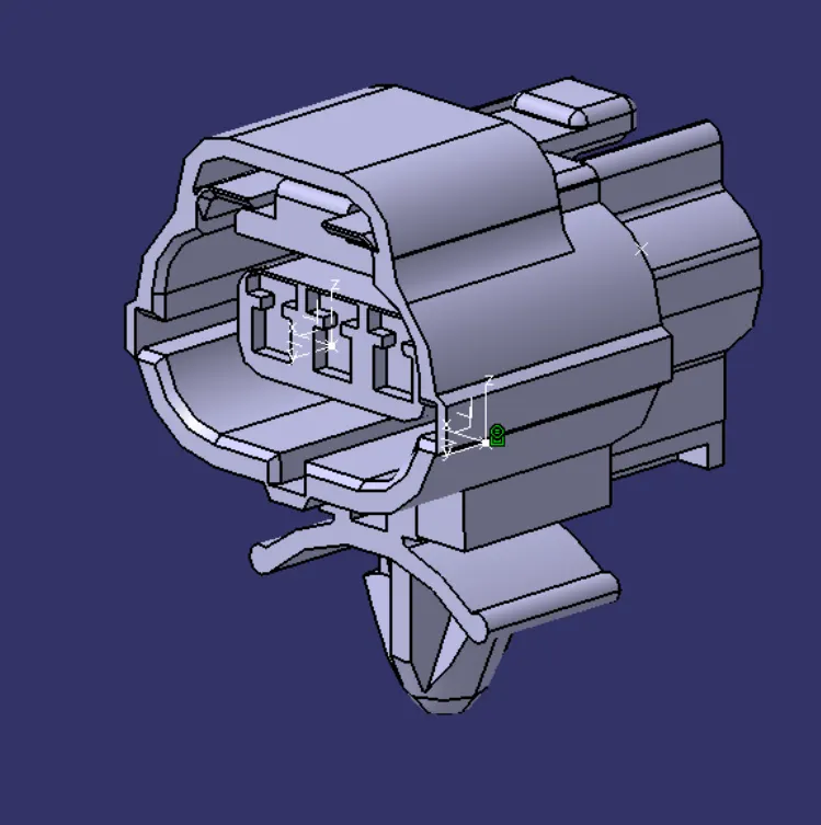
Once the command “connect electrical devices” is selected, then we have to select either connector/cavity clip. Once the connector part is selected, then the preview of mating points is shown in catia as per below diagram,
CATALOG CREATION
to create catalog we have to follow the below procedure
File--> New---> Catalog Document ---> OK
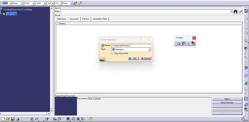
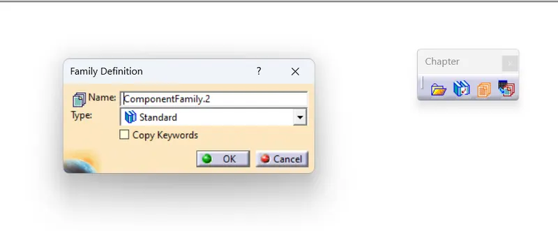
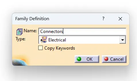
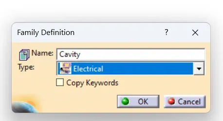
Add Famiily ---> Type: electrical ---> name:(we can remane as we need )---->OK----> save (chose the location where we need to save)
Connectors
Cavity
catalog created
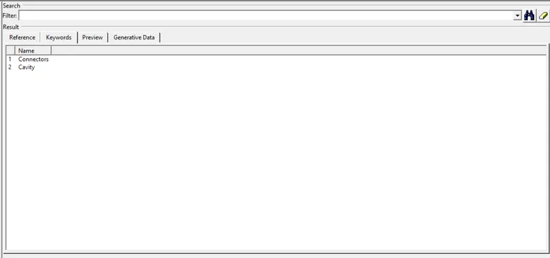
Catalog is created
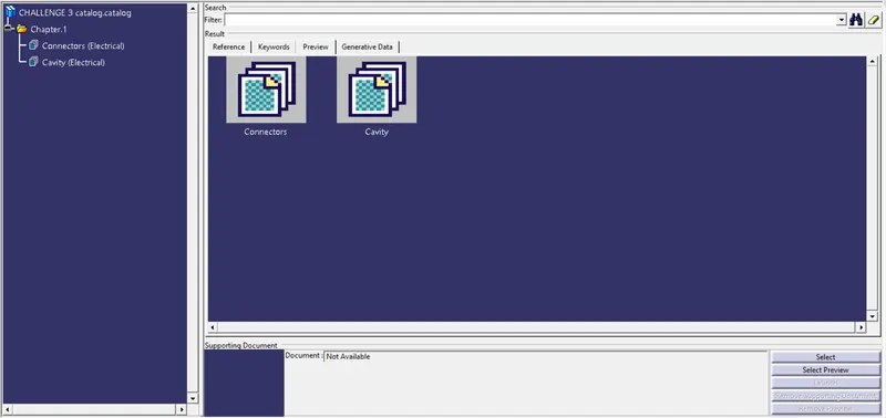
Conclusion:
in this challenge we gain knowledge on how to create an electrical component with part file using Electrical Part Work Bench and Creating Catalogs,