Week 12- Final project
- Development of a Door Trim panel
Creation of CAD model considering following inputs as like in OEM and tier1 companies
- a) Class A surface
- b) Nominal thickness : Refer master sections
- c) Attachment strategy :
Find a attachment strategy for the door panel complete work.
Use Push pin with Dog house for Lower substrate – Door panel attachment
Use heat stakes for part to part attachment
Introduction:
Door panels serve as an interface between the interior of the car and the inner workings of the door, and between vehicle occupants and the door. They are expected to meet a variety of design specifications regarding safety, aesthetics, and functionality. In addition, they are expected to continue the material theme of the dashboard and pillars while concealing intricate electrical and mechanical components for operating locks, windows, and other features. The door panel has evolved from a simple two-part system of latch and simple winding mechanism to a more sophisticated enclosure. Doors currently have an inner full-width panel consisting of electronic windows, central locking system, and speakers. These panels typically consist of a foamed core covered with either textiles or plastics.

Class-A Surface:
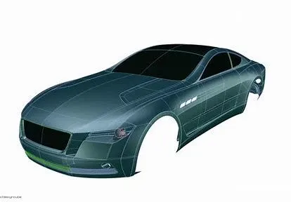
A-class surfaces are those aesthetic/ free form surfaces, which are visible to us (interior/exterior), having an optimal aesthetic shape and high surface quality. Mathematically class-A surfaces are those surfaces which are curvature continuous while providing the simplest mathematical representation needed for the desired shape/form and does not have any undesirable waviness. Products are not only designed considering the functionality but special consideration is given to its form/aesthetics which can bring a desire in one’s mind to own that product. This is only possible with high-class finish and good forms. This is the reason why in design industries Class-A surfaces are given more importance. In automotive design, a class-A surface is any of a set of freeform surfaces of high efficiency and quality. Although, strictly, it is nothing more than saying the surfaces have curvature and tangency alignment – to ideal aesthetical reflection quality, many people interpret class A surfaces to have G2 (or even G3) curvature continuity to one another. Class A surfacing is done using computer-aided industrial design applications. Class-A surface modellers are also called "digital sculptors" in the industry. Industrial designers develop their design styling through the A-Surface, the physical surface the end user can feel, touch, see etc.
Class-B surface:
Class-B surfaces are the secondary surfaces that can be seen sometimes, but are less important, such as the inside of your glovebox, ash tray, etc. These must be smooth and "error-free" as well, but are not held to the standards that class-A surfaces are.
Class-C surface:
Class C surfaces are the backside surfaces that can have tool marks, flash and other imperfections without hurting appearance, function, etc.
Plastic Part:
When designing parts for injection molding,the manufacturing process is an important consideration. Injection molding is a process in which solid thermoplastic resin pellets are melted, injected into a mold, and then cooled back to a solid state in a new form. During both the injection and cooling stages of the manufacturing process, there are several factors that may affect the quality of the final product and the repeatability of the manufacturing process. Although it is not always possible to follow all recommendations, outlined on the following pages are some of the most fundamental guidelines when designing parts for injection molding.
B-Side Features:
Boss:
Bosses are used to facilitate the registration of mating parts, for attaching fasteners such as screws, or for accepting threaded inserts.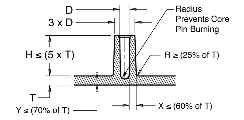
Wall thicknesses for bosses should be less than 60 percent of the nominal wall to minimize sinking. However, if the boss is not in a visible area, then the wall thickness can be increased to allow for increased stresses imposed by self-tapping screws.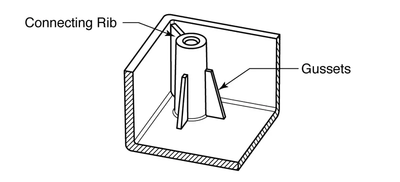
The base radius should be a minimum of 0.25 X thickness. Bosses can be strengthened by incorporating gussets at the base or by using connecting ribs attaching to nearby walls
Dog House:
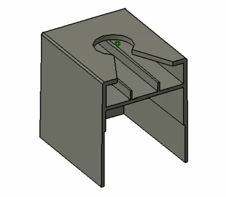
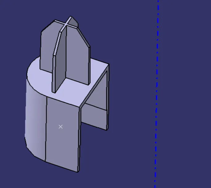
Dog house is an engineering feature used in plastic trim design. Dog houses are used as supporting features. Sometimes other engineering features like snaps; locators etc. are mounted on them to increase their strength. Dog houses are subjected to draft analysis to prevent breakage of the component during ejection from mould cavity. Dog house and other engineering components are built on a B-surface.
Dog House Design:
Dog houses are used as supporting feature.Dog houses are subjected to draft analysis to prevent breakage of the component during ejection from mould cavity. Dog house and other engineering components are built on a B-surface.
Ribs:
Ribs are thin, wall-like features typically designed into the geometry of a part to add internal support to walls or other features like bosses. In a similar fashion, gussets are support features that reinforce areas such as walls or bosses to the floor.
Ribs provide a means to economical stiffness and strength in molded parts without increasing overall wall thickness. They also facilitate:
- Locating & arresting components of an assembly.
- Providing alignment in mating parts.
- Acting as stops or guides for mechanisms.
A well-designed rib will overcome the following disadvantages:
- Increase part weight and cost proportional to the increase in thickness.
- Increase molding cycle time required to cool the larger mass of material.
- Increase the probability of sink marks.
Typical uses of Ribs:
- Covers, cabinets and body components with long, wide surfaces that must have a good appearance with low weight.
- Rollers and guides for paper handling, where the surface must be cylindrical.
- Gear bodies, where the design calls for wide bearing surfaces on the center shaft and on the gear teeth.
- Frames and supports.
Ribs design involves 5 main issues:
- Thickness.
- Height.
- Location.
- Quantity.
- Manufacturability.
Rib Geometry:
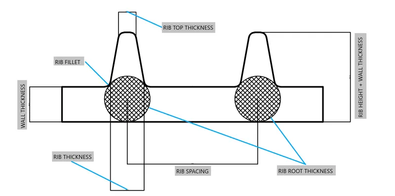
1)Rib Thickness:
Ribs should be designed to be 50-60 percent of the nominal wall thickness. Thinner does not provide much structure and may be hard to fill. Thicker ribs are tempting, but they can begin to introduce sinks on the cosmetic surface.
Bottom Rib Thickness :( 0.3 to 0.6) * Wall Thickness
Note: Top Rib Thickness should be minimum of 0.75mm.
2)Rib height:
For maximum effectiveness, rib height should be no more than three times the nominal wall thickness. Since the rib will be thinner than the wall, it may be hard to fill it if it is taller.
Rib Height= (3 to 5) * Wall Thickness.
3)Rib spacing:
Increase the number of ribs rather than their height in order to increase stiffness. Ribs should be spaced a minimum of two times the nominal wall thickness apart from one another.
Rib Height/Rib width ratio = 3:1 –steel.
Rib Height/Rib width ratio = 2:1 –preferred
4)Rib draft:
A minimum 0.5-degree draft will ensure that they release from the tool during molding.
Rib draft = (0.5 to 1) degree.
5)Rib coring:
Core thick ribs from the back or below to create a blank area and thinner rib walls. This will help mitigate cosmetic sinks.
6)Rib fillet:
Fillet at feature intersections to increase rib strength.
Rib fillet = 0.125 * Wall Thickness.
7)Rib Root Thickness:
It is the thickness at the intersection of the Rib and Wall of the plastic component.
Rib Root Thickness = (0.3 to 0.5) * Wall Thickness
Wall Thickness:
- Maintain a wall thickness of less than 5 mm because thick walls can lead to long cycle times and poor mechanical properties.
- Avoid large variations in wall thicknesses in order to simplify flow pattern and minimize variations in shrinkage that can lead to warpage.
- Avoid abrupt changes in wall thickness, as this can create stress concentration areas that may reduce a part’s impact strength. Wall thickness changes should have transition zones that reduce the possibility of stress concentrations, sinks, voids, and warp.
- Avoid gating near an area with a large variation in wall thickness because hesitation and race tracking can create non-uniform flow and shrinkage.
Snap Fits:
Snap-fits involve pushing a projection on one part past an obstruction on a mating part. They rely entirely for their effect on the elasticity of plastics. Generally, one part is more or less rigid while the other part is flexible or resilient. Depending on the design, the joint can be permanent or releasable. Both parts can be plastics - either the same or different types, or one part can be a foreign material such as a metal shaft or a laminated circuit board. There are three principal types of snap-fit:
- the cantilever snap-fit, also known as a snap hook, catch spring, spur, or lug.
- the cylindrical or ring snap-fit.
- the spherical snap-fit.
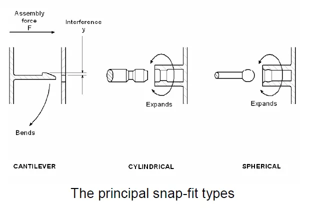
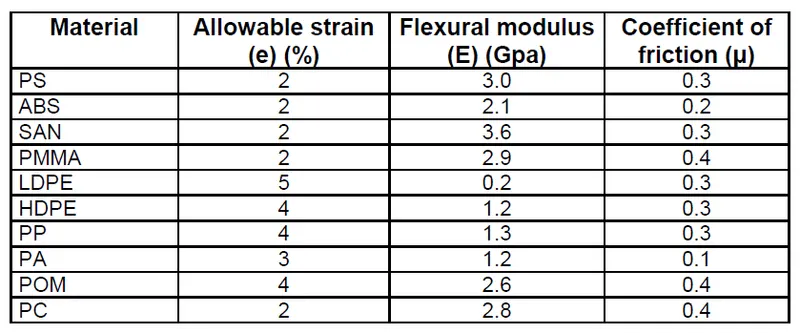
The cantilever or hook - in more detail. The cantilever type clicks or snaps into engagement when it is pushed past a catch on a mating part. The hook has a tapered face with a shallow engagement angle to help it past the obstruction. A releasable snap hook has a second tapered face set at a release angle to allow it to be removed again. The release angle is greater than the engagement angle, to make release relatively difficult. If release is too easy, the snap-fit will not act as a reliable fastener. When the release angle approaches 90 degrees, removal by pulling is virtually impossible and the snap-fit becomes a permanent joint. When the cantilever hook is pushed past the catch, it is forced to flex. The amount of deflection is equal to the interference between hook and catch, and this must be kept to a dimension that does not exceed the allowable strain for the cantilever material. The table shows approximate design data for a range of unfilled materials. The allowable strain figures are for a snap-fit that is used just a few times. If it is to be used once only, the strain figures can be doubled. The figures in the table should be taken as a guide only. For accurate design, you will need to get grade-specific figures from your materials supplier.
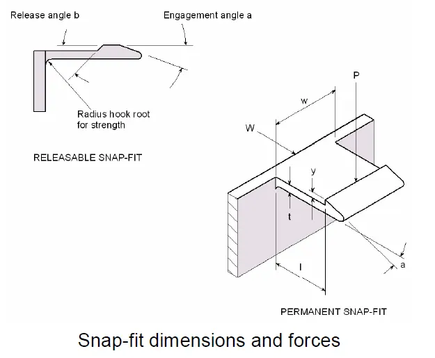
For a snap hook with a constant cross section, the maximum deflection Y can be worked out from this equation:
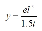
The equation assumes that only the snap hook flexes. In many cases, the moulding the face that it is attached to will also flex a little. This can be regarded as a safety factor. If the hook mounting is rigid, then you should reduce the calculated maximum deflection by a safety factor. The normal force P needed to move the snap hook through deflection y comes from this equation:
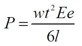
This result can be used to work out the force W needed to engage the snap fit with the catch.
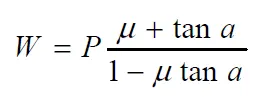
In the case of a releasable snap hook, the same formula can be used to work out the release force by substituting the release angle b for the engagement angle a. If the release force approaches the tensile strength of the snap hook, then it is likely to break as you try to release it. Similarly, the catch will shear off if its cross-section is too weak compared with either the engagement force or release force. Of course, if the snap hook is properly designed, the release force will always be greater, even in a releasable design.
CREATION OF DOOR TRIM USING CLASS A SURFACE
The following component Class A surface is given:-
1. ARM REST
2.MAP POCKET
3.BOTTLE HOLDER
4.LOWER SUBSTATE
CLASS A SSURFACE DATA
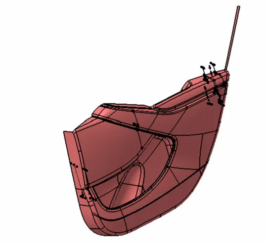
Detailed view
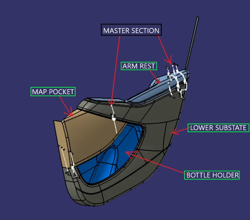
CREATION OF ARM REST WITH ENGINEERING FEATURES
CLASS A MODIFICATION
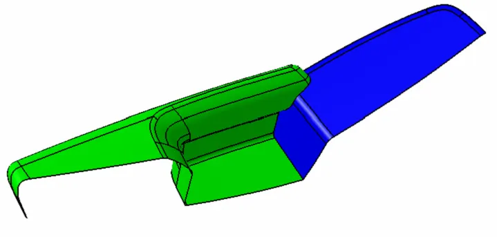
Before going to create Arm Rest we have look Class A surface for Corections and other missing surfaces are there are not
CLASS A SURFACE
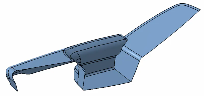
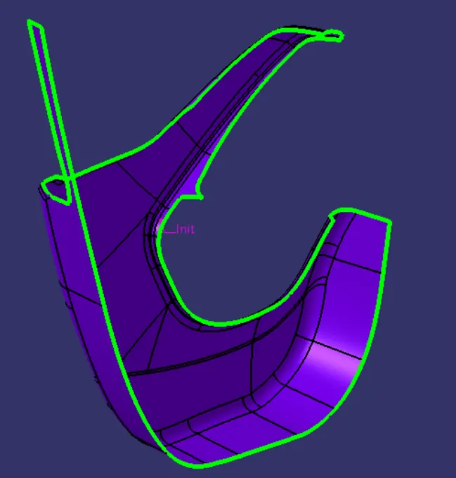
Checking for discontunity in given surface
to know we have two methods 1.joining and 2. Boundry creation by these two methods we find out whether the given surface is ok or not
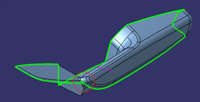
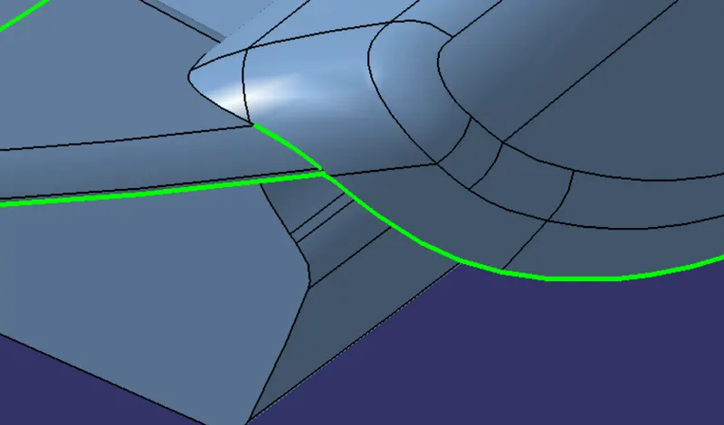
so we have some error in Class A Surface so we need to do some modifications to correct the surface .
we are going to use following commands
1.Multiple-Extract
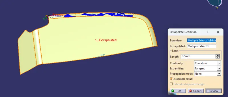
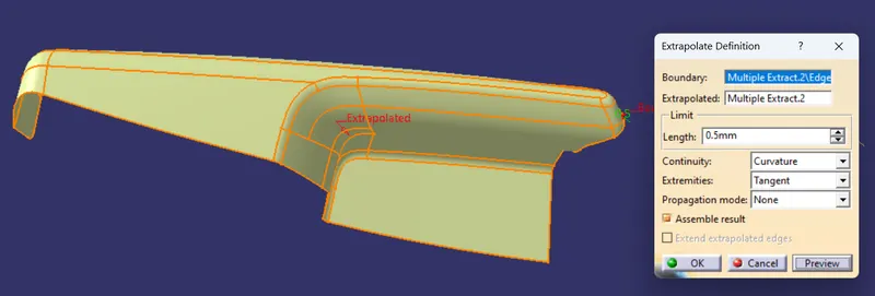
2.Extraplote
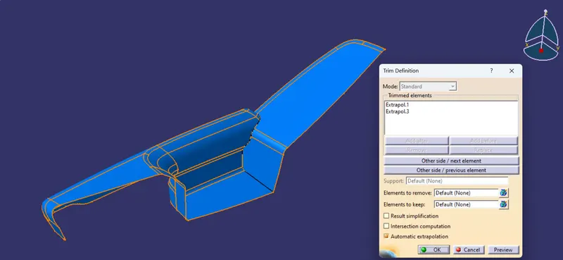
3.Trim
4.Join etc....
1.Multiple Extract
we need to extrack the class a like below shown to work with it
Extrapolated
Extrapolated
TRIM
CLASS A
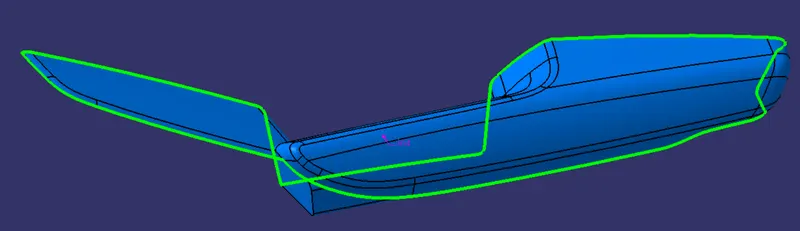
after doing some modification now class a surface looks fine
TOOLING AXIS
Before creating Tooling axis we need to take mould design consideration and core cavity
by looking into Arm Rest we can make sure that it can be ejected by CORE and another by SIDE CORE so we need to create tooling axis for both CORE and SIDE CORE.
TOOLING CORE
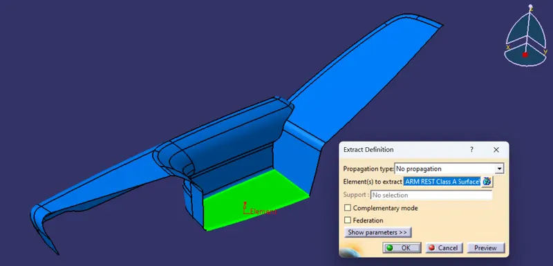
Extract
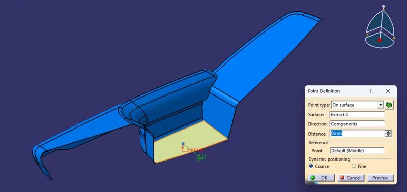
Point creation
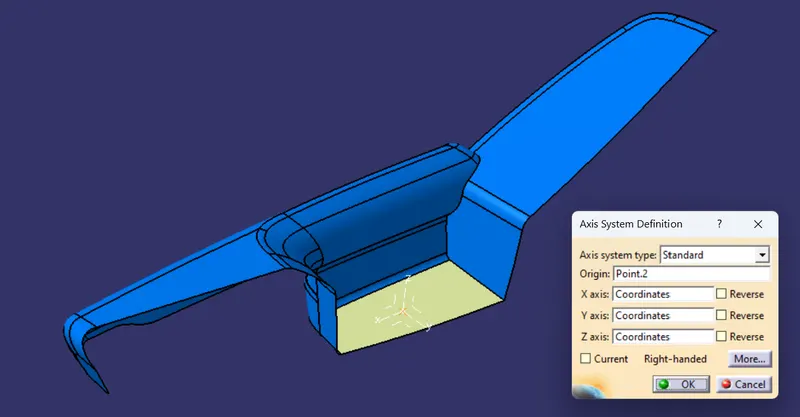
Axis System
Intersect
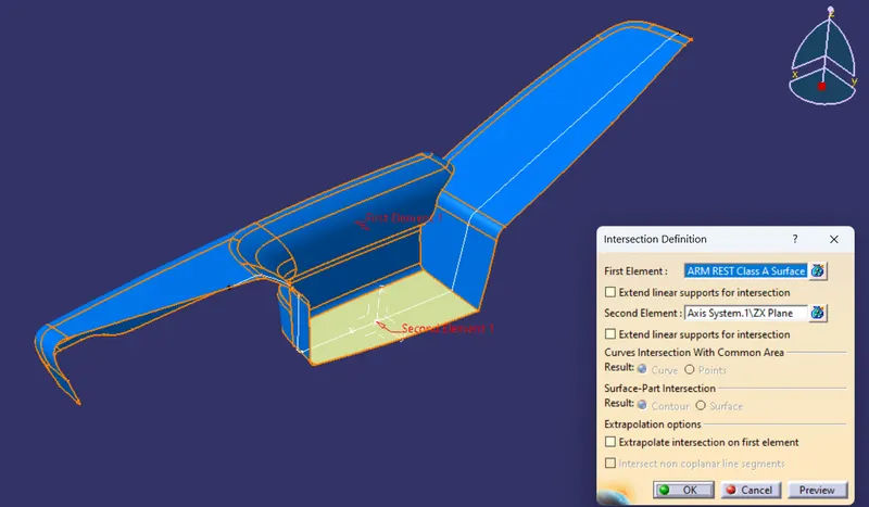
Tooling axis
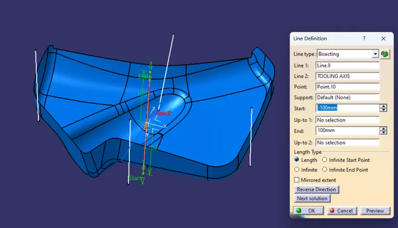
Tooling axis is created by using bisecting line command to create this line we need two lineso those lines are created by using intersect data.
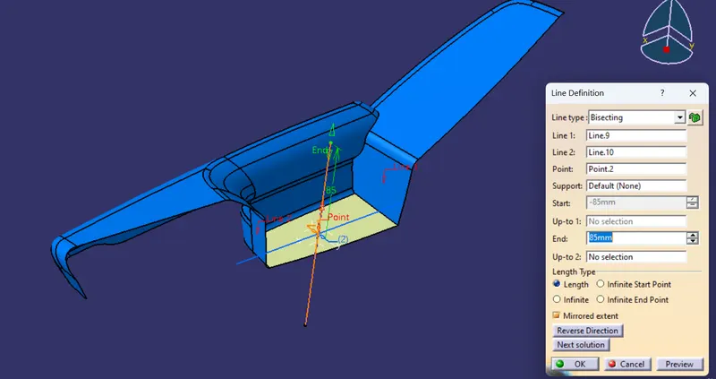
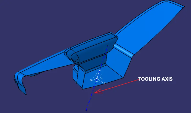
SIDE CORE TOOLING AXIS
Extract
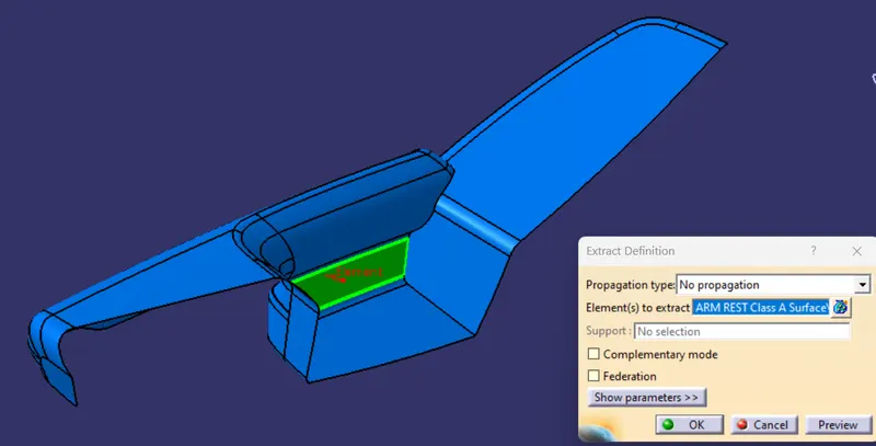
Point
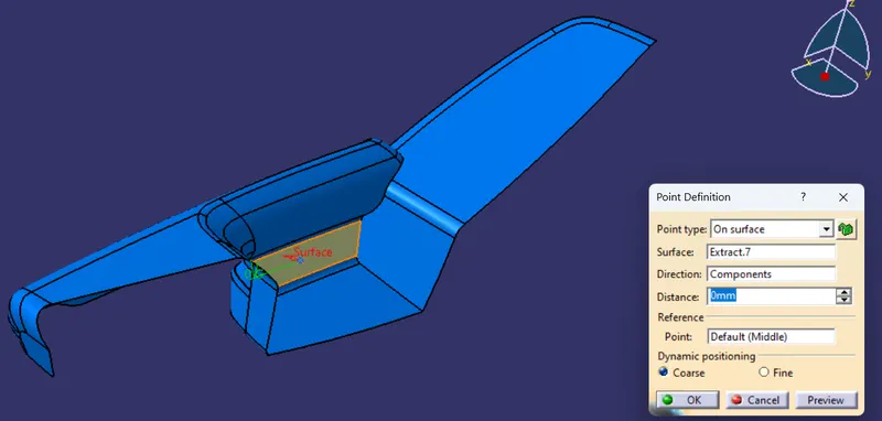
Tooling axis
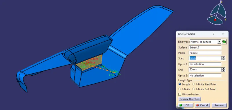
SIDE CORE TOOLING AXIS
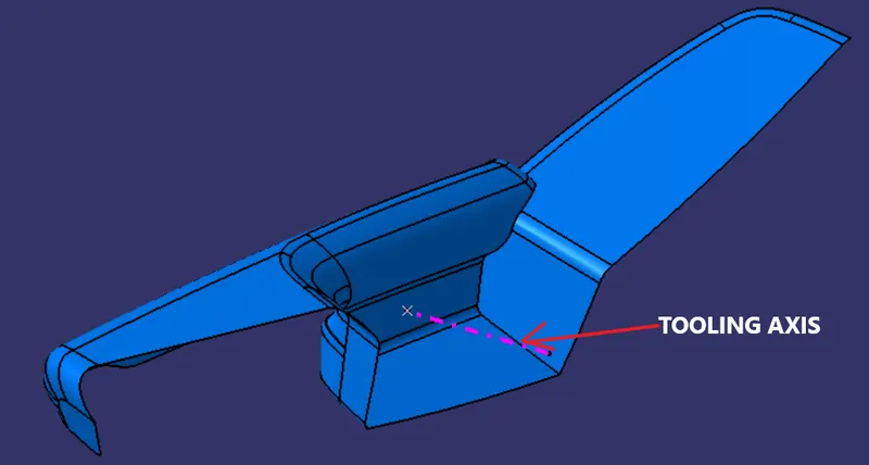
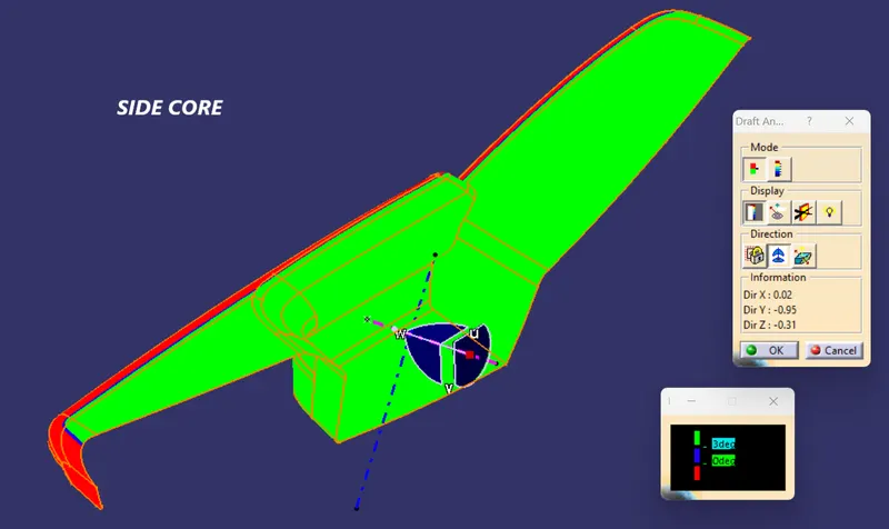
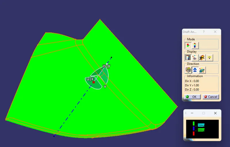
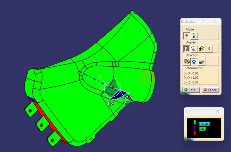
DRAFT ANALYSIS
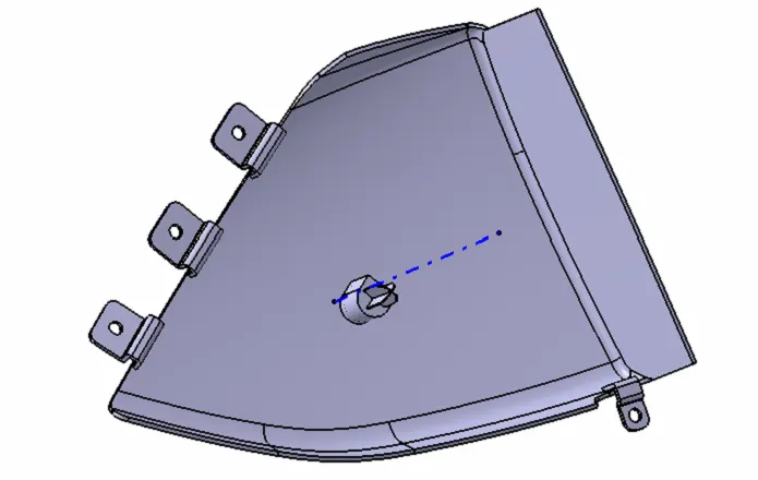
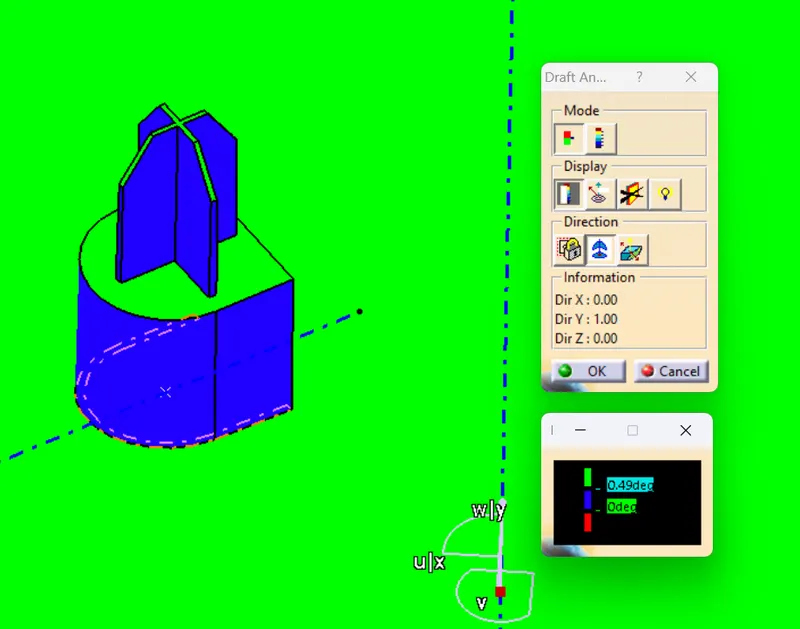
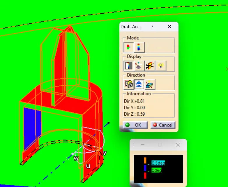
- The draft analysis command enables you to detect if the part you drafted will be easily removed. This type of analysis is performed based on color ranges identifying zones on the analyzed element where the deviation from the draft direction at any point, corresponds to specified values.
- The maximal draft analysis accuracy is 0.01 deg. According to the graphic card performance, this accuracy can be debased.
- The different mapping analyses of the same surfaces cannot be displayed simultaneously, even if you have set the mapping analyzes in no show. You need to visualize them one after the other.
CORE SIDE
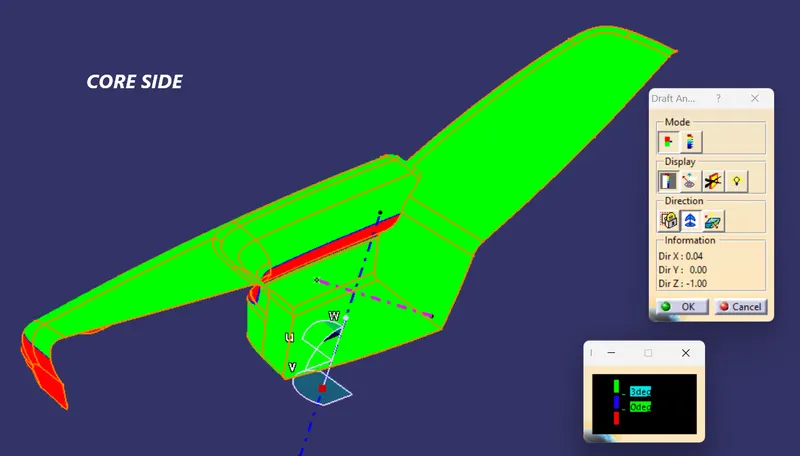
SIDE CORE
CLASS B SURFACE
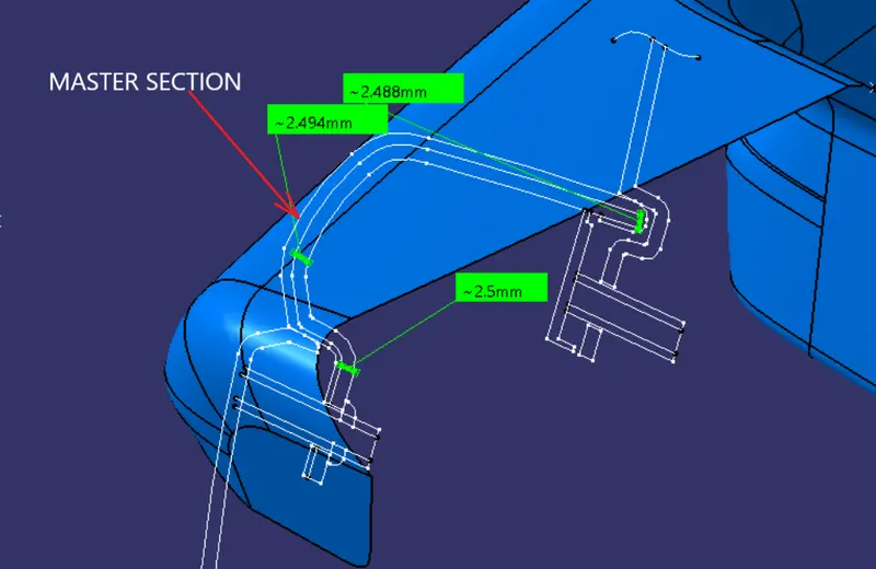
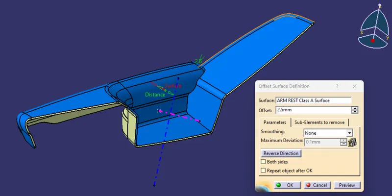
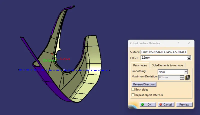
To create B Surface we need to have the data of wall thickness
to know the wall thickness we have master sections that are provided so by this we came to know wall thickness is 2.5mm
MEASURING WALL THICKNESS
CLASS C SURFACE
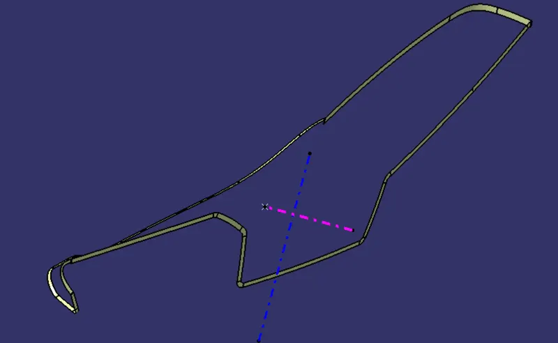
CLOSED SURFACE
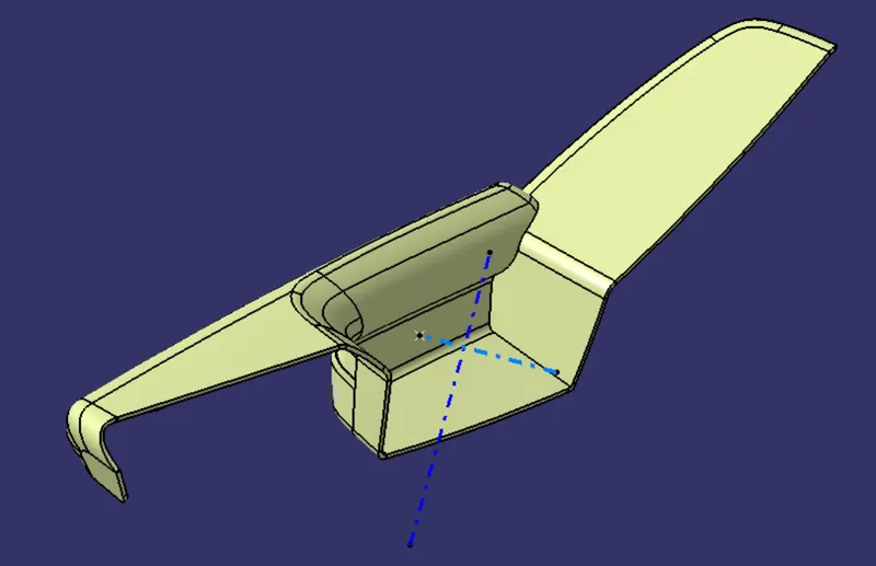
B SIDE ENGINEERING FEATURE CREATION
CREATION OF MAP POCKET WITH ENGINEERING FEATURES
2. MAP POCKET
CLASS A SURFACE
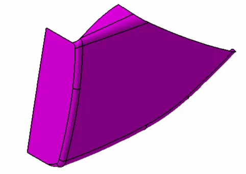
Checking for discontunity in given surface
to know we have two methods 1.joining and 2. Boundry creation by these two methods we find out whether the given surface is ok or not
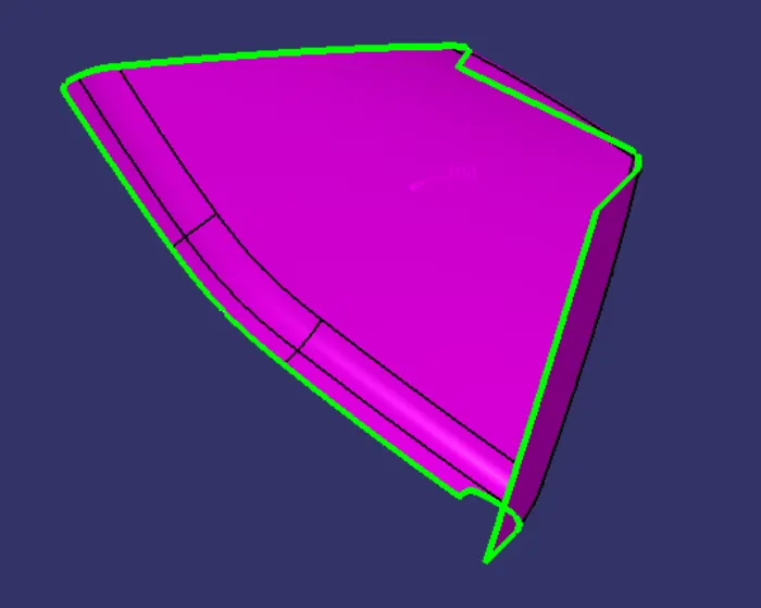
so we can conclude that Class A surface is Ok
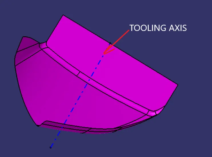
TOOLING AXIS CREATION
in this surface we will get only one tooling direction that is CORE SIDE
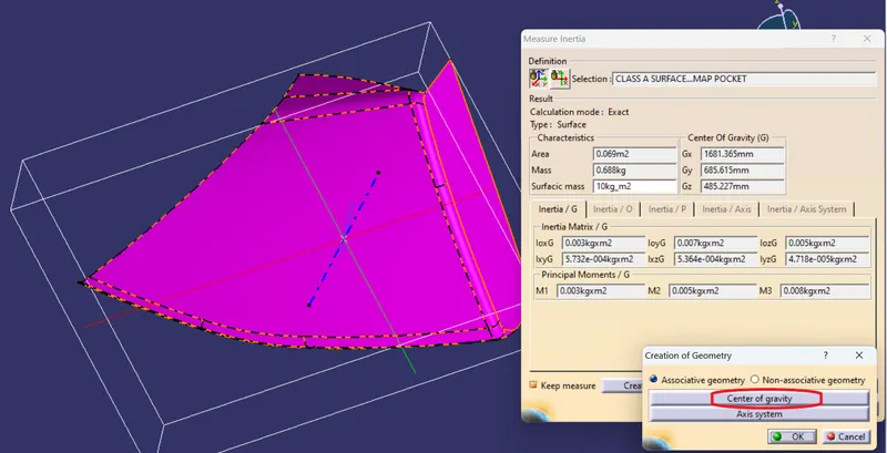
POINT
point is created as shown in figure
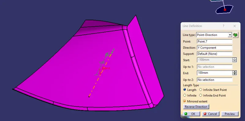
LINE
DRAFT ANALYSIS
CLASS B SURFACE
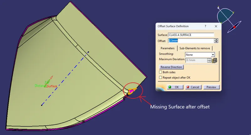
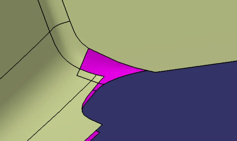
to correct that surface we will use FILL command
CLASS B SURFACE
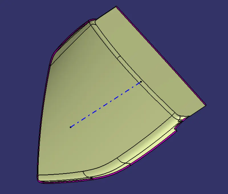
CLASS C SURFACE
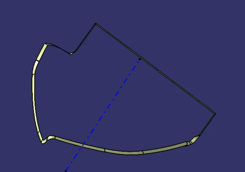
CLOSED MAP POCKET
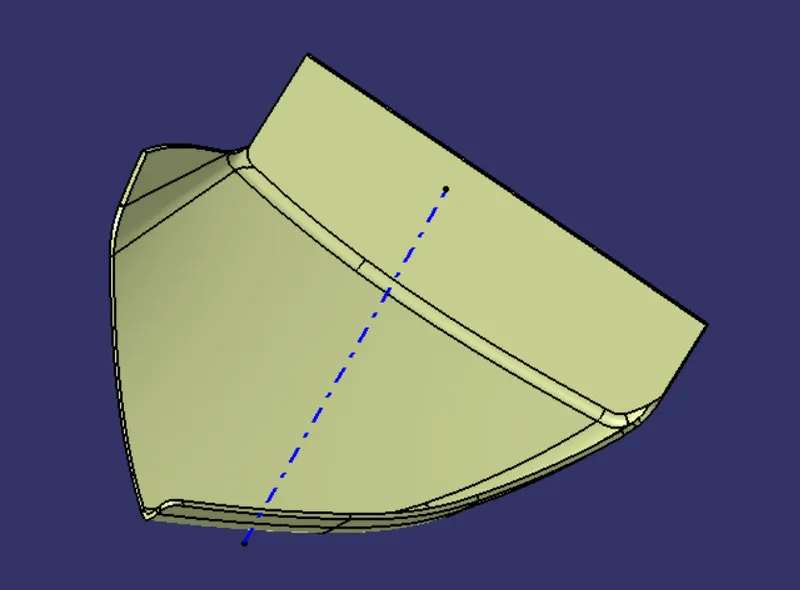
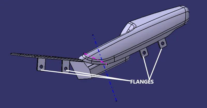
B SIDE ENGINEERING FEATURES
1.Flanges
According to Master Section
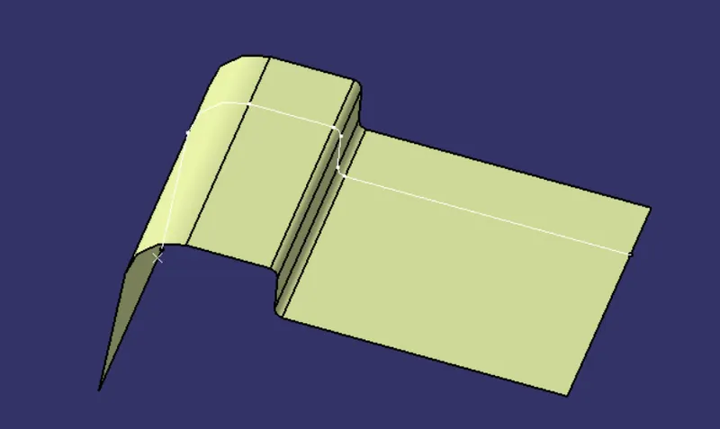
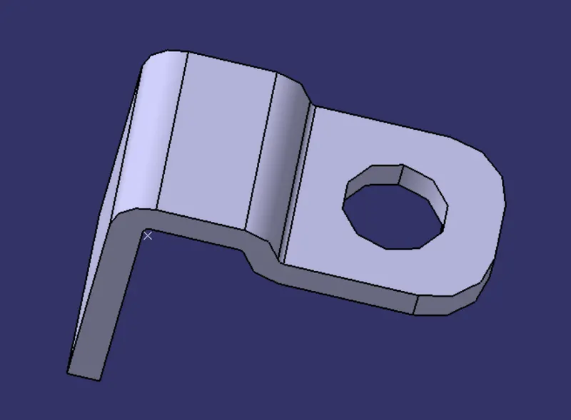
Doug House
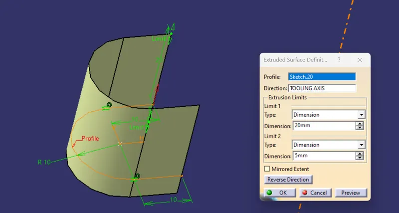
1.Sketch
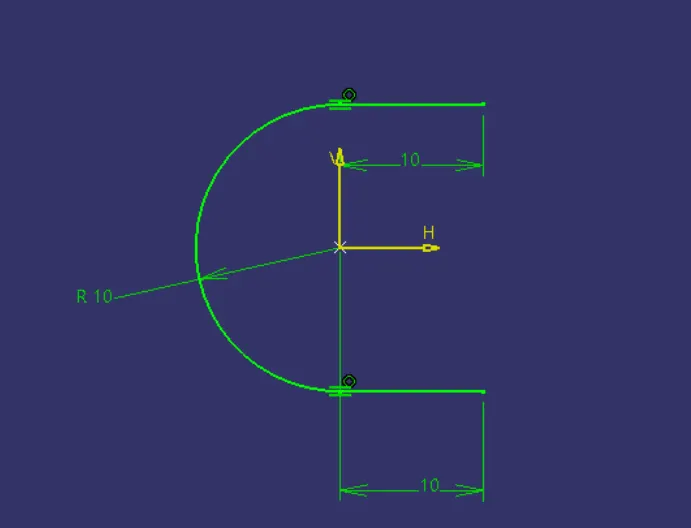
Extrude
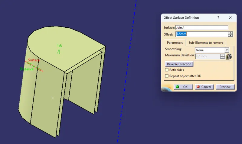
OFFSET 1.5mm
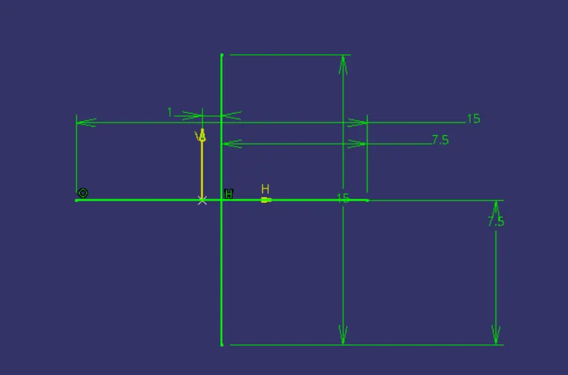
4 way locator
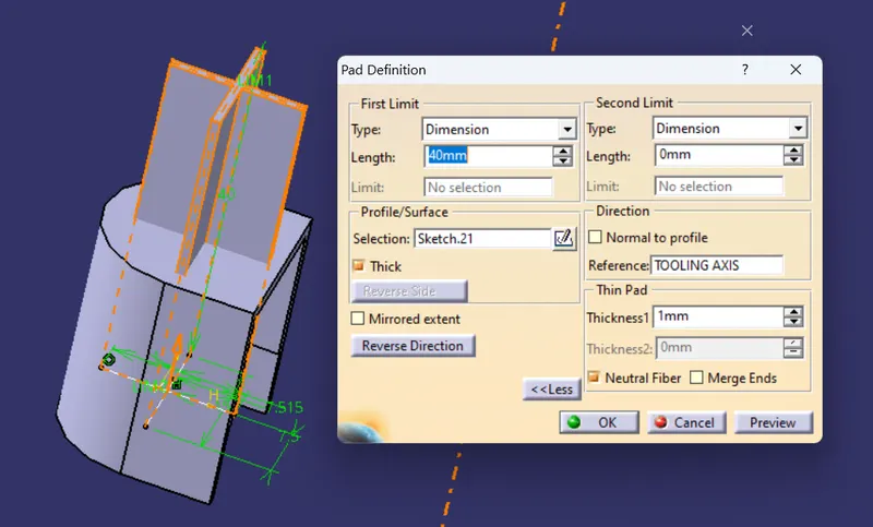
B SIDE FEATURE
DRAFT ANALYSIS
4 WAY LOCATOR
CORE SIDE
SIDE CORE
B SIDE ENGINEERING FEATURE
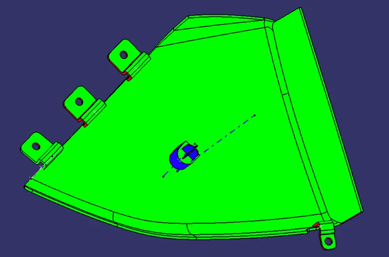
4. MAP POCKET
CLASS A SURFACE
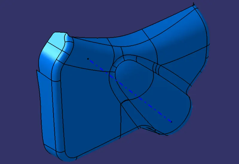
Checking for discontunity in given surface
to know we have two methods 1.joining and 2. Boundry creation by these two methods we find out whether the given surface is ok or not.
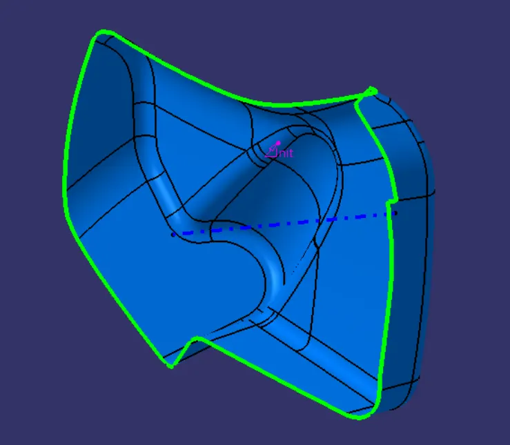
so we can conclude that Class A surface is Ok.
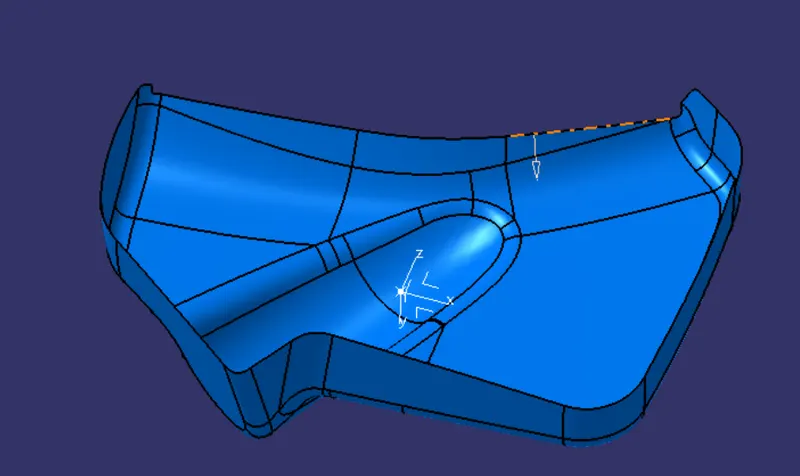
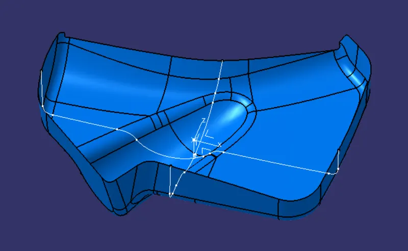
TOOLING AXIS CREATION
1. POINT
Tooling axis is created by using centre of gracvity method as shown in fig
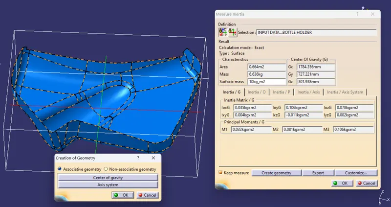
2. AXIS CREATION
3. INTERSECT
4.BISECTING LINE
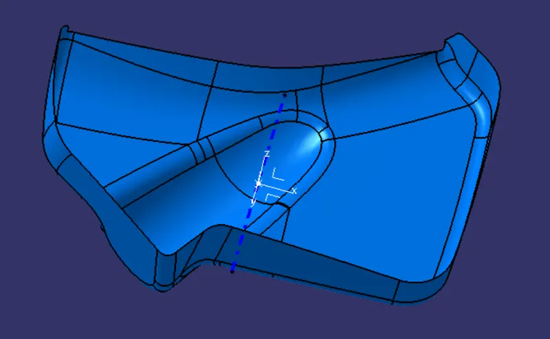
5.MAIN TOOLING AXIS
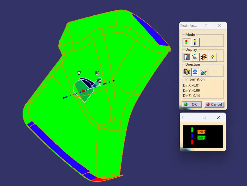
DRAFT ANALYSIS FOR CLASS A SURFACE
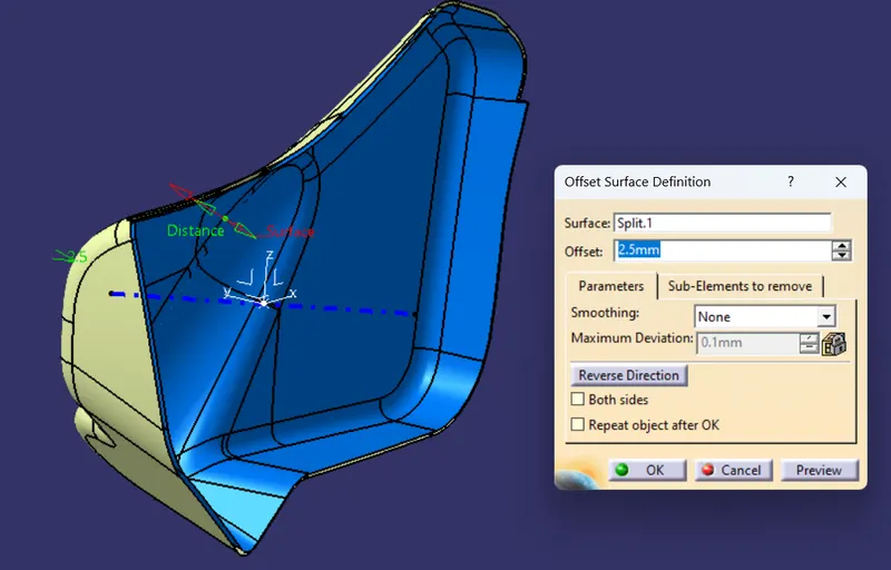
CREATION OF CLASS B SURFACE
Wall thickness is measured by Master- Section
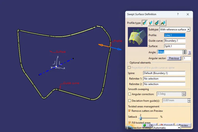
CREATION OF CLASS C SURFACE
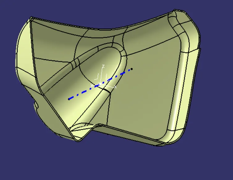
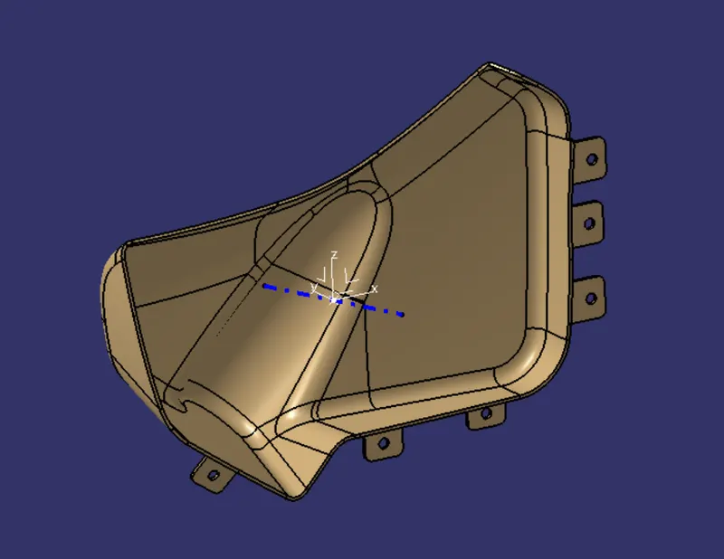
CLOSED BOTTLE POCKET
B SIDE ENGINEERING FEATURES
DRAFT ANALYSIS
4. LOWER SUBSTATE
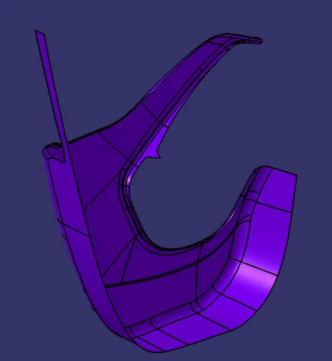
CLASS A SURFACE
class a check
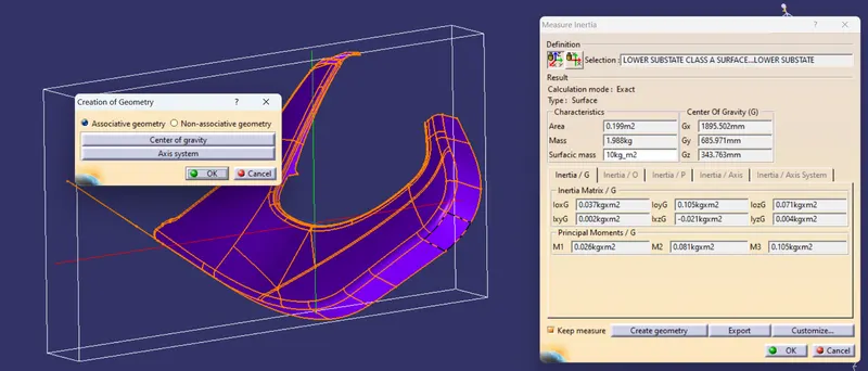
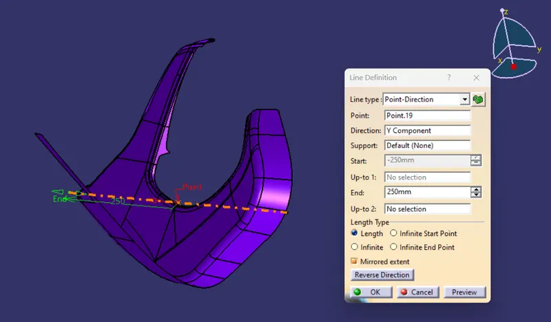
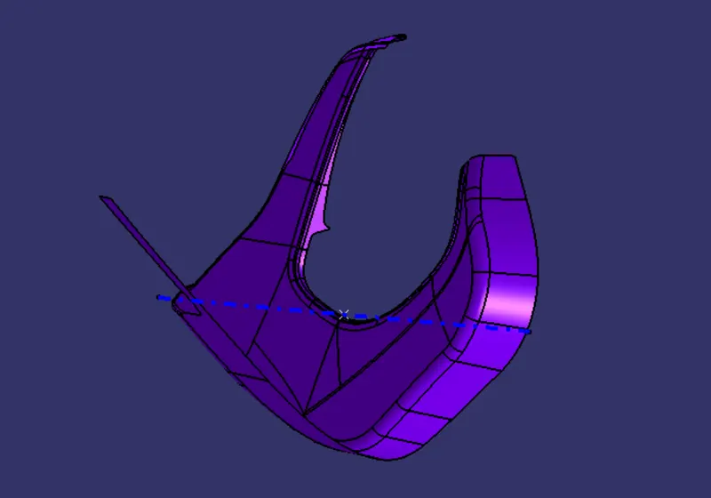
TOOLING AXIS CREATION
1. POINT
2.LINE
MAIN TOOLING AXIS
CLASS B SURFACE
CLASS C SURFACE

CLOSED LOWER SUBSTATE
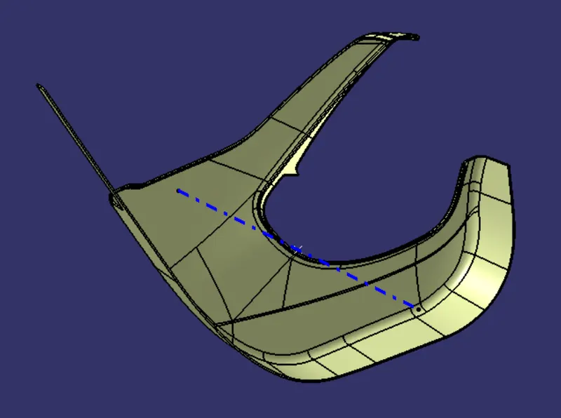
B SIDE ENGINEERING FEATURES
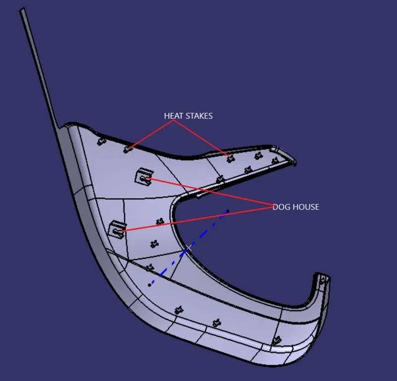
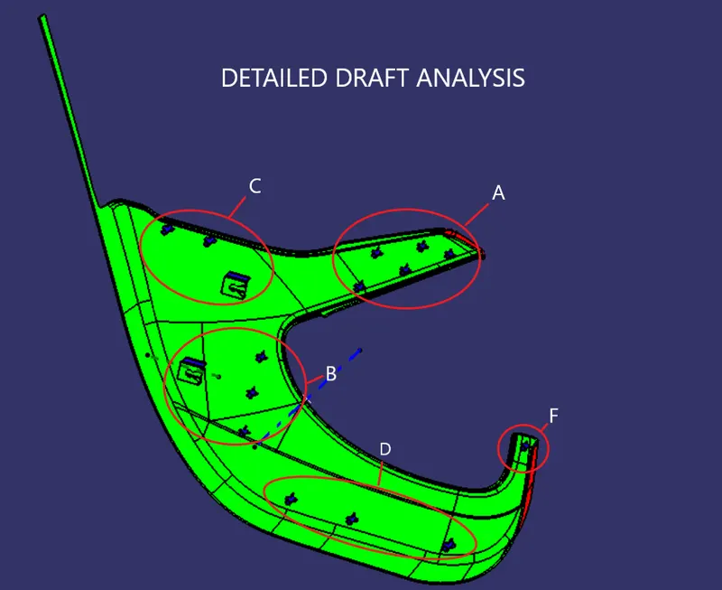
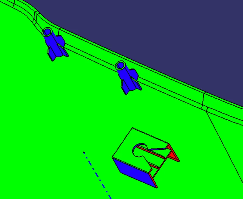
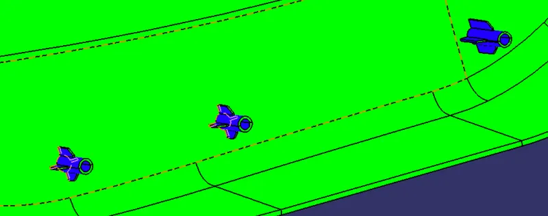
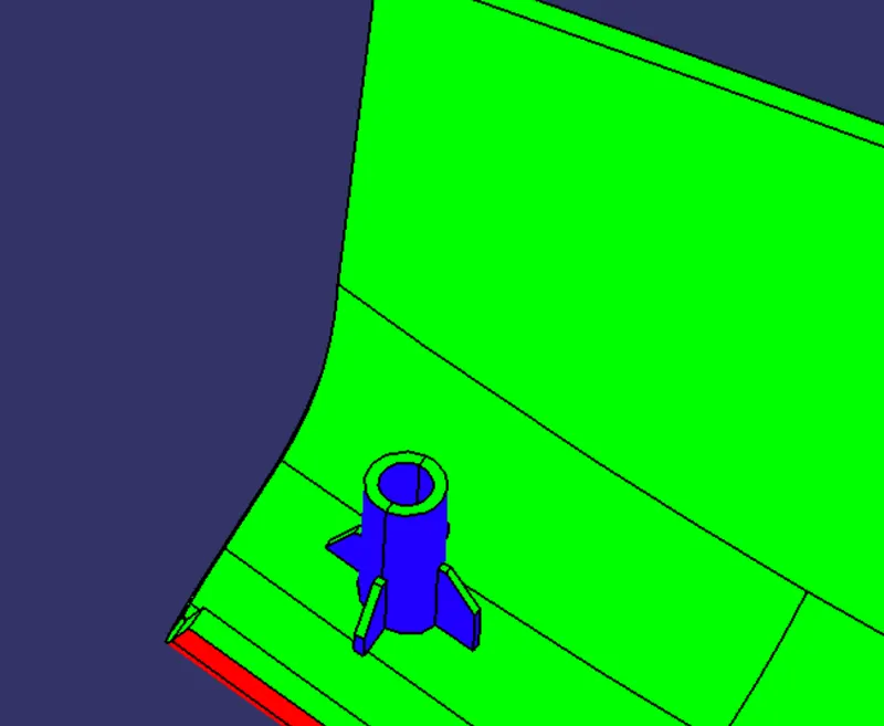
DOG HOUSE DRAFT ANALYSIS
MAIN TOOLING AXIS
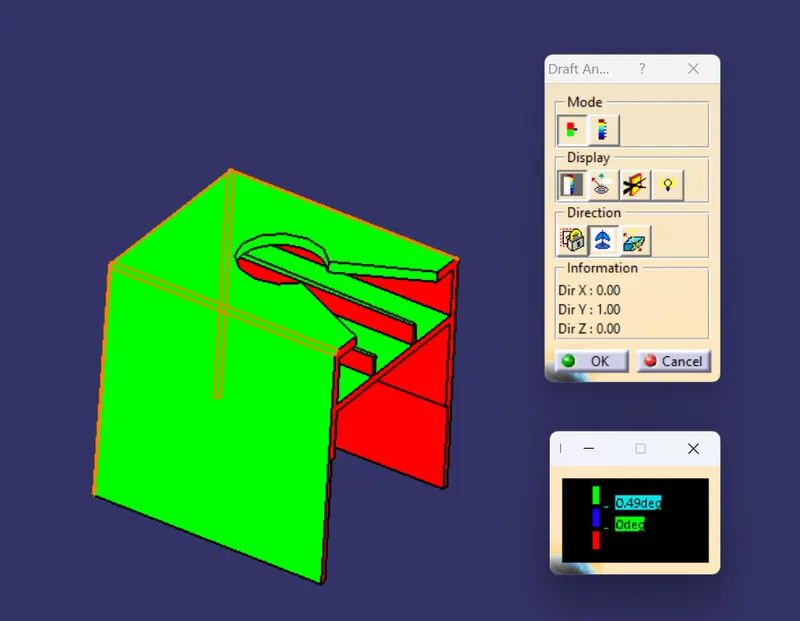
SIDE CORE
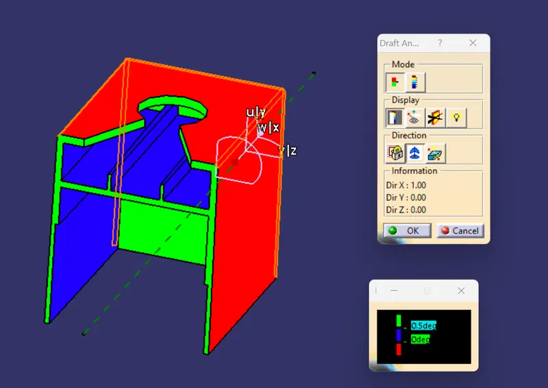
B SIDE ENGINEERING FEATURE DRAFT ANALYSIS MAIN TOOLING AXIS
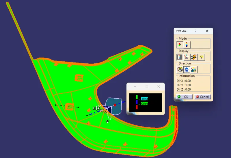
DETAIL DRAFT ANALYSIS VIEW
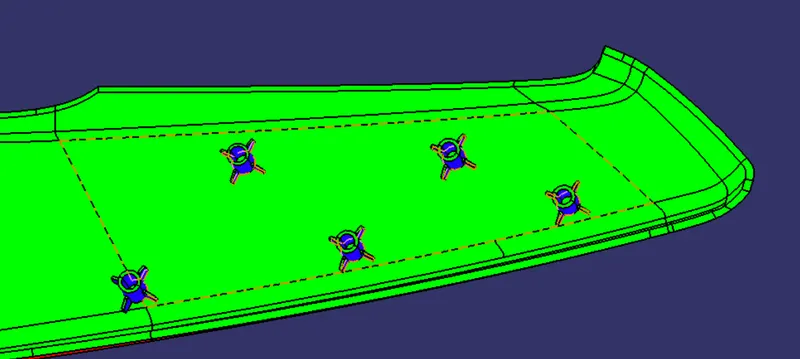
A.
B.
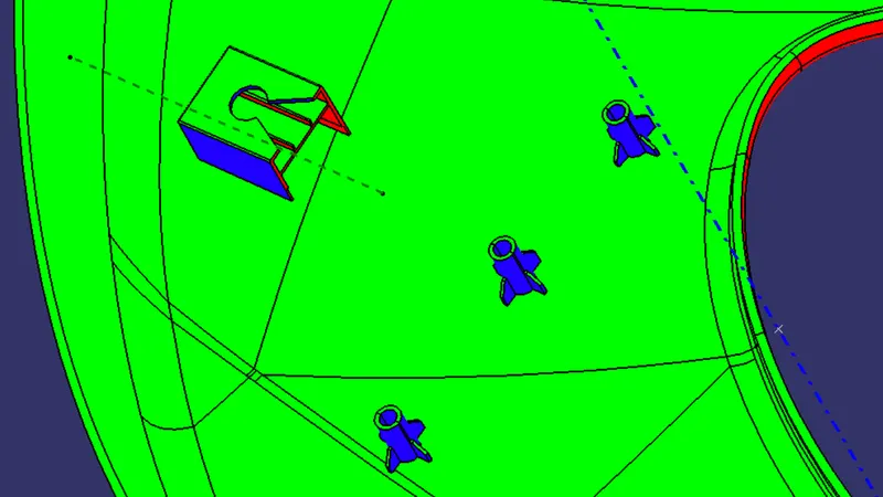
C.
D.
E.
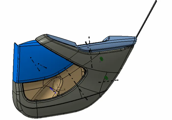
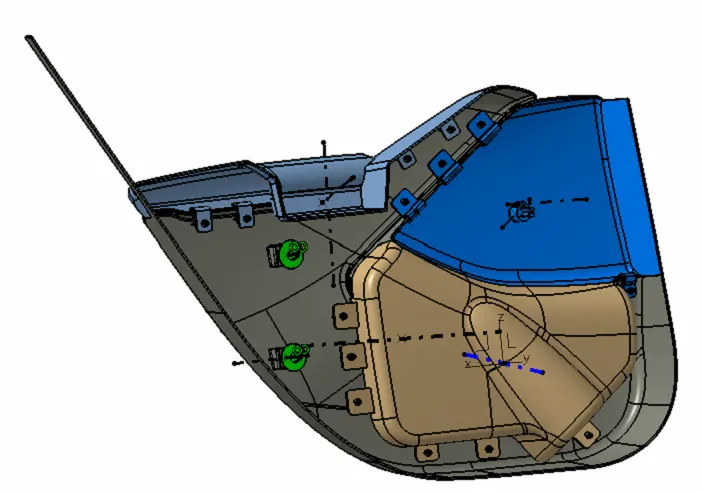
ASSEMBLY VIEW
CONCLUSION
Door trim is created by Using given Class A Surfaces and Master sections.
B Side Engineering Features are Created Based On requirements and refereing Mastersections
Draft analysis is made considering Main Tooling axis and also Side Core Tooling axis.....