Project 2
Wiring Harness Routing of Back Door Panel of a Car
In this challenge, we will perform the Wiring Harness Routing of a Back Door Panel and at the end will prepare a flattened view drawing for the same. All packaging rules & the best industry practices will be followed during this process.
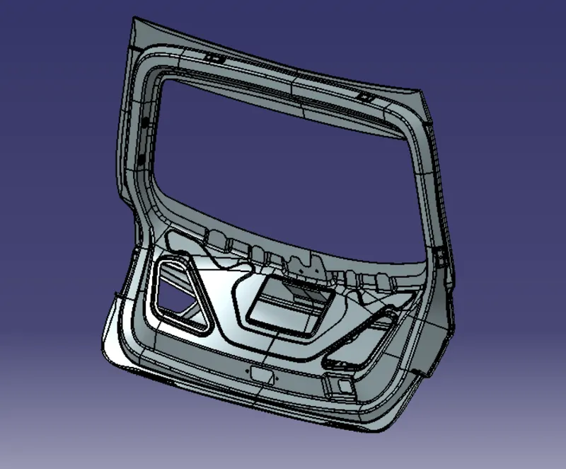
The steps that need to be followed for executing this task are as follows:
- Identifying the electrical components in the model
- Defining the mechanical components electrically or Importing the data from the catalogue
- Setting up the assembly by placing the required connectors, clips, clamps, etc
- Proper routing of the bundle without any interference
- Preparation of flattening file & 2D drawing creation
The electrical components in this model are Tail Lights & Number Plate Lights. These lights require power or current to operate hence the wires or bundles that we are going to route today will help us understand the length & path of the wire & also the connectors, clips and other parts that are needed for this project.
PROCEDURES AND STEP FOLLOWED FOR WIRING HARNESS ROUTING
- Created new product file and named it as “BACK DOOR WIRING HARNESS CONTEXT”.
- In that product I have opened the CAD file given for the Tail gate.
- Created another product file inside the wiring harness context assembly file.
- And named “GEOMETRICAL HARNESS BUNDLE BACKDOOR”
- I have made ready all the required connector, Clips, Clamps and protective CAD Data.
- Each components defined electrically by giving respective features.
- Created catalogue documents for particular groups.
- After creating the catalogues, added required connectors and clips from the catalogue browser.
- Using manipulation tool placed all the connectors and clips as required.
- Now for starting the routing first electrically defined the geometrical bundle assembly file using the command Geometrical Bundle.
- That leads to create new multi-blanchable part file inside the GEOMETRICAL HARNESS BUNDLE BACKDOOR.
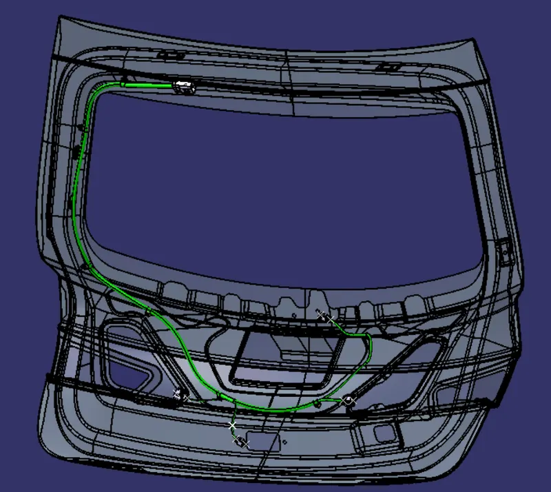
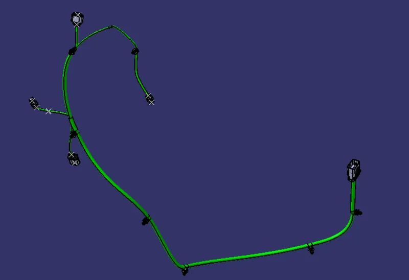
- Then click on the multi-branchable command led to wiring harness installation work bench from there Using branch definition command started the routing.
- Given all the required parameters like wire radius, bending radius, slack and route definition.
- Created Branch points for adding branches on required positions.
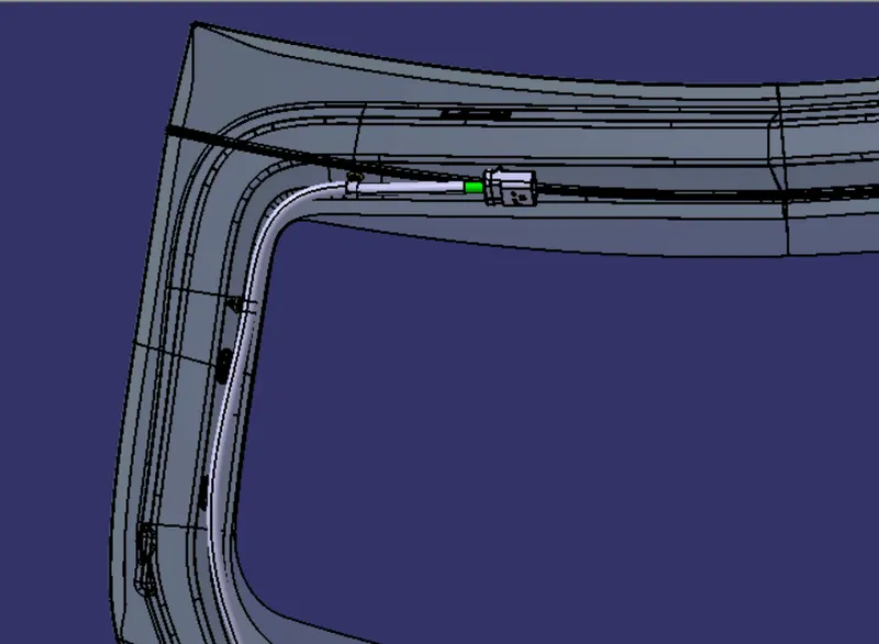
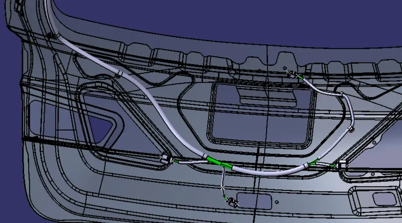
- After well completion of all the connection routing added protective coverings for the wires.
DESIGN CRITERIA AND PACKAGING ASSUMPTIONS:
- Wiring harness routing shall provide ease in manufacturing, accessibility, easy removal, and easy maintenance of attached equipment and wiring harness.
- Routing through small structural holes and openings shall be avoided, minimize chaffing and handling of the wiring harness during installation.
- Avoid the harness routing and clipping in the Blind zone of the Operator during harness assembly or in service.
- Routing shall offer protection against possible damage through common misuses such as being handhold and temporary support for test equipment.
- Provide additional slack to the harness according to the surroundings and harness bending requirements.
- Ensure the routing meets the clearance requirements with different surrounding parts.
- Avoid routing over the bolts, near to the bolted joints. It may damage the harness or puncture the harness. Keep harness away from panel mounting screws.
- Avoid harness routing near sharp edges, if not possible provide protection to the harness.
- The maximum distance between two clips on a straight branch is 200mm.
- Provide Clips and clamps if the harness is going to bend at multiple locations.
- The use of too many sheet-metal brackets should be avoided.
- The branch length should be more than 50 mm.
- Min distance between clip and branching point to be 25 mm.
- Min distance between two branch breakouts should be 50 mm.
CONNECTORS DATA
in this project we are going to Use 2 Types of Connectors
- Two Pole Connectors
- Four Pole Connectors
- Inter connector
a) TWO POLE CONNECTOR
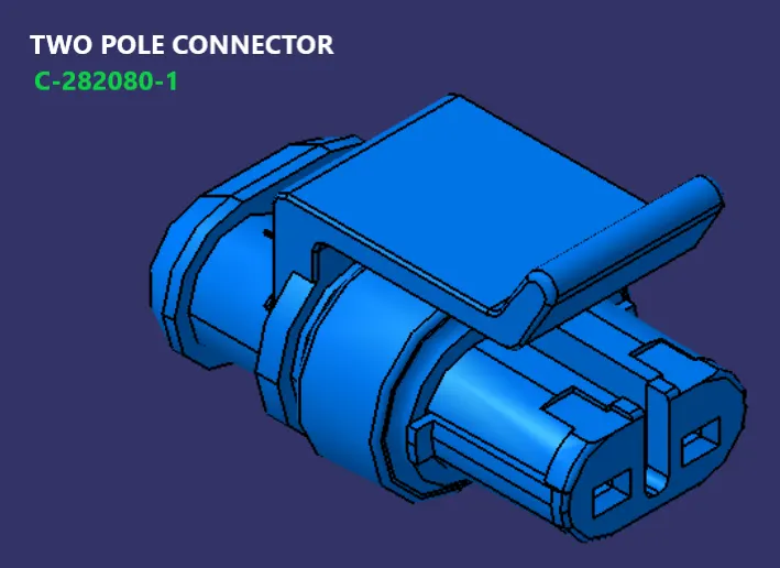
are used for Oil pressure sensors,Engine Coolent Temp Sensor,Vehicle speed sensor,Neutal position sensor. total we use 5 Two pole connectors to Route the harness.
b) FOUR POLE CONNECTOR
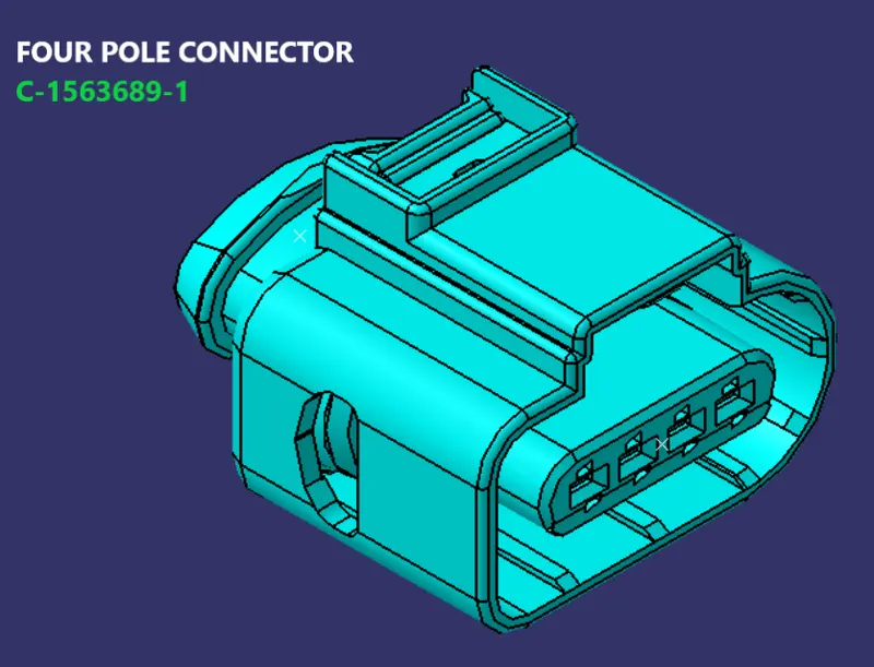
Four pole connector is used to route the Injector and Cam Shaft position sensor in this project we have used 16 for Injector and 4 for Cam Shaft sensor.
c) INTER CONNECTOR
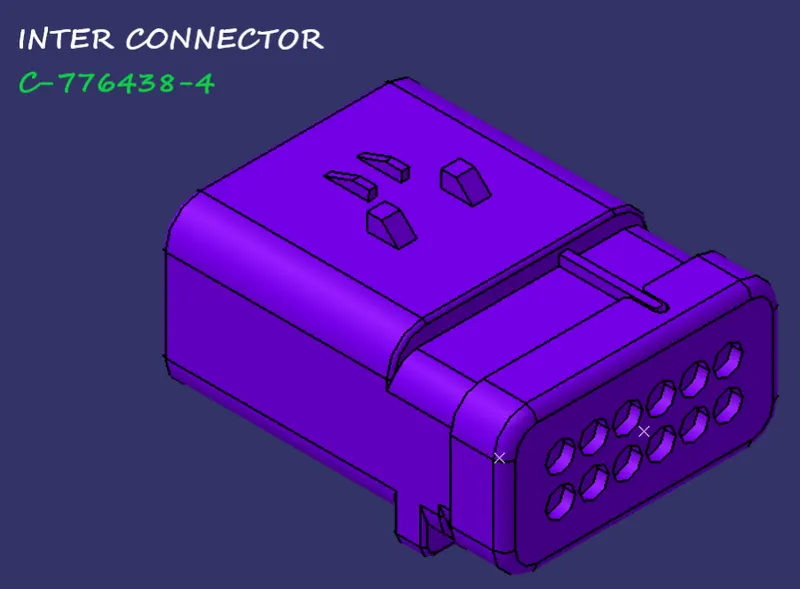
inter connector is used to connect the Engine Harness with Vehicle Harness System.
HARNESS SUPPORTS
to route the harness we need mountings here we use
1.Furr Tree
2.P Clamp
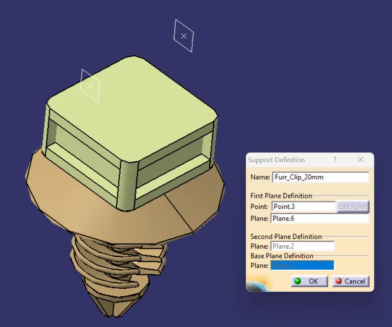
1. FURR TREE
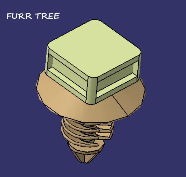
Furr tree is used as support for harness where the harness is routed over the head and tied using cable ties.
it is inserted to threaded profiles so it wount come easily and makes sure proper fitments.
DEFINING CONNECTORS AS ELECTRICAL PART
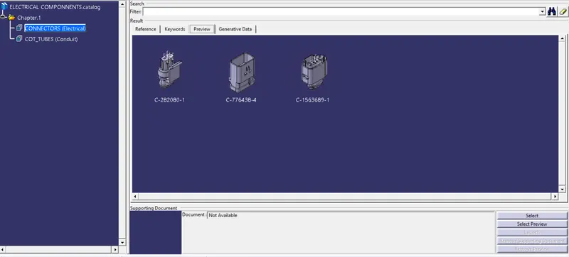
1. TWO POLE CONNECTOR(C-282080-1)
a.Define as Connector
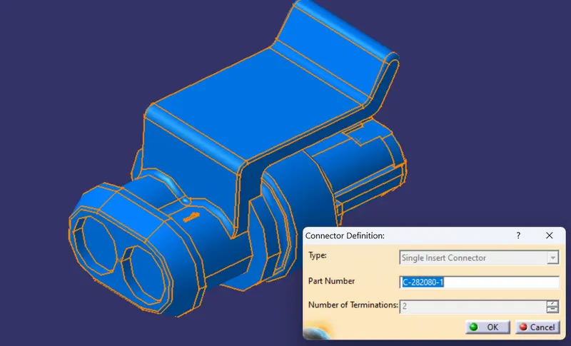
b. Connector Connection point defination
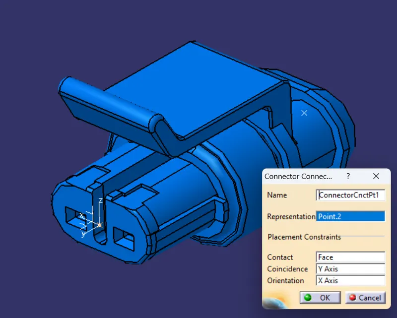
c) Bundle Connection point defination
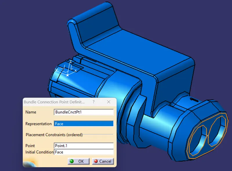
Connector is defined as Electrical part.
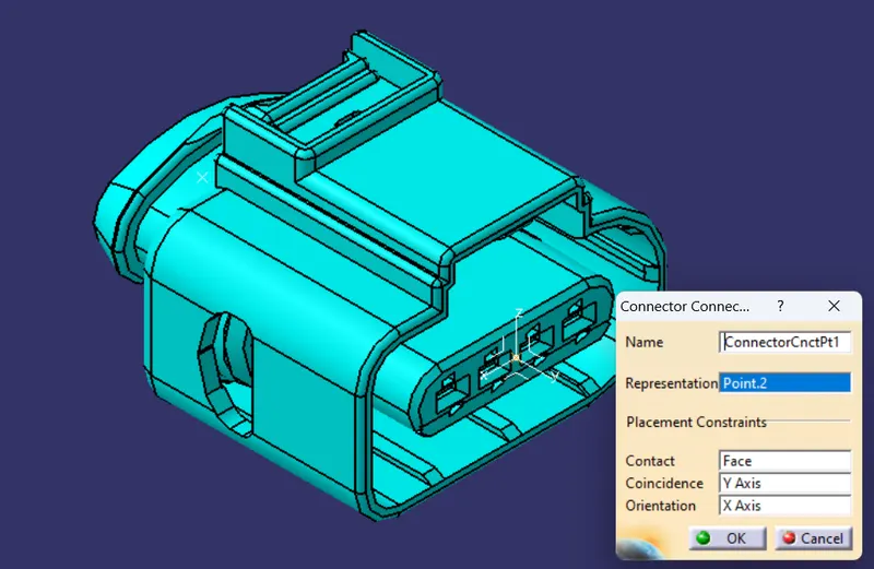
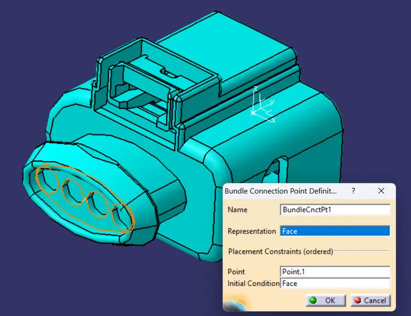
2.FOUR POLE CONNECTOR(C-1563689-1)
a) As Connector
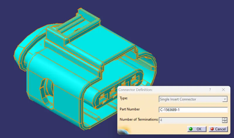
b) Connector Connection point defination
c) Bundle Connection point definition
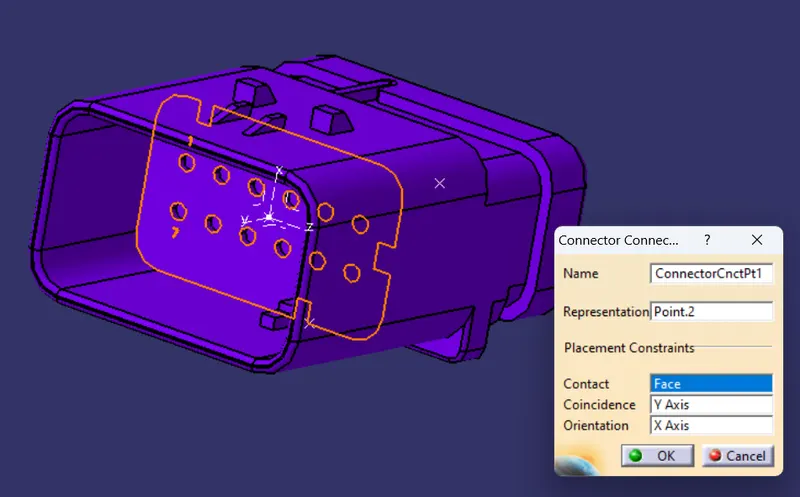
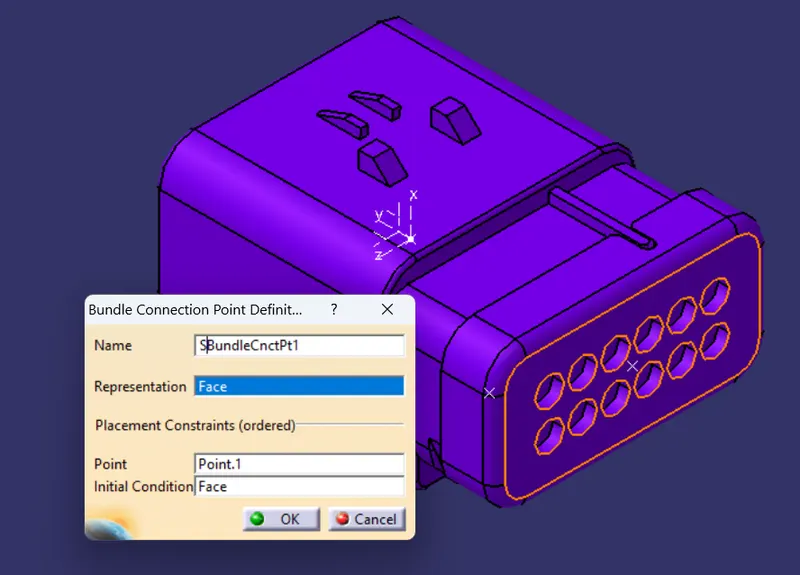
3.INTER CONNECTOR(C-776438-4)
a) As Connector
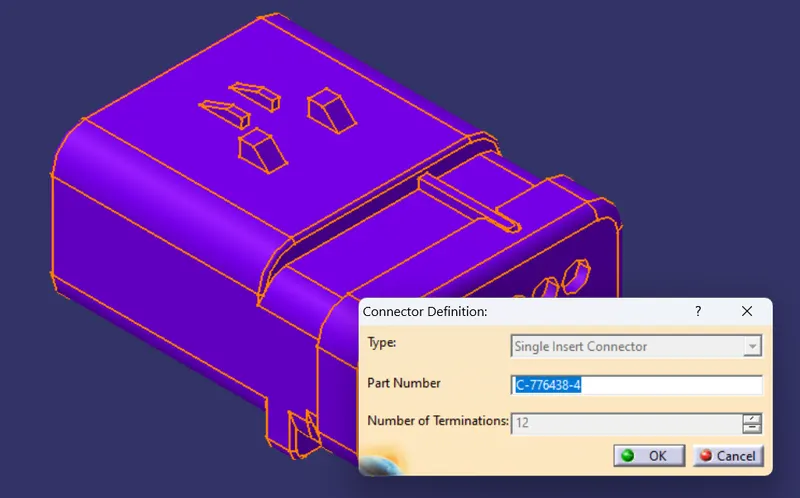
b) Connector Connection Point defination
c) Bundle connection point Defination
DEFINING MOUNTINGS AS ELECTRICAL PART
1. FURR TREE
CATALOUGE CREATION
CONNECTOR CATALOUGE CREATION
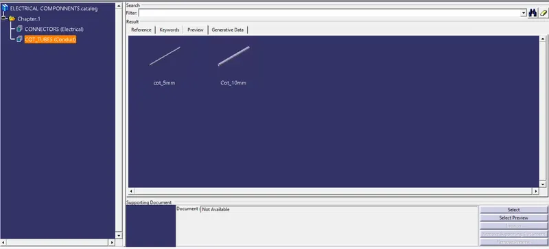
COT TUBE CATALOG CREATION
HARNESS ROUTING
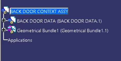
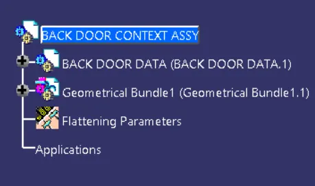
Before creating Harness assy we need to create CONTEXT Assy and Add Back Door Data as shown in the fig
all the electrical Components are inserted in to Geometrical Bundle Assy as shown in the Fig
We need to assemle the connectors at the desired location by using Move,Snap,and Campass tools
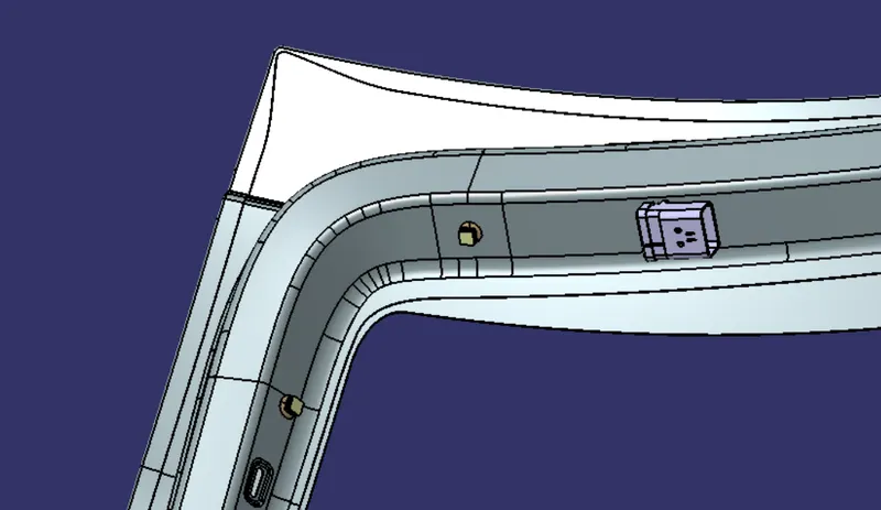
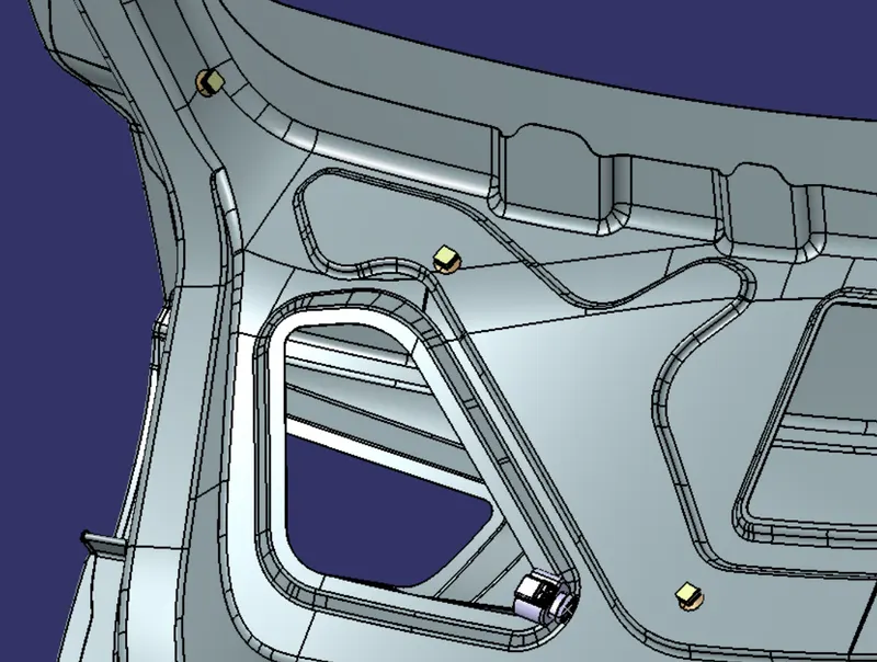
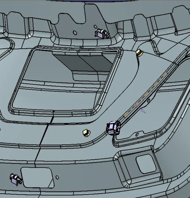
above figures showns the mounting of Connectors and Mounting clips in Desired position
Bundle Routing
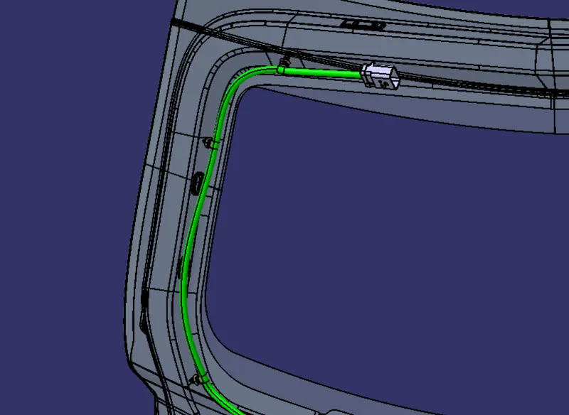
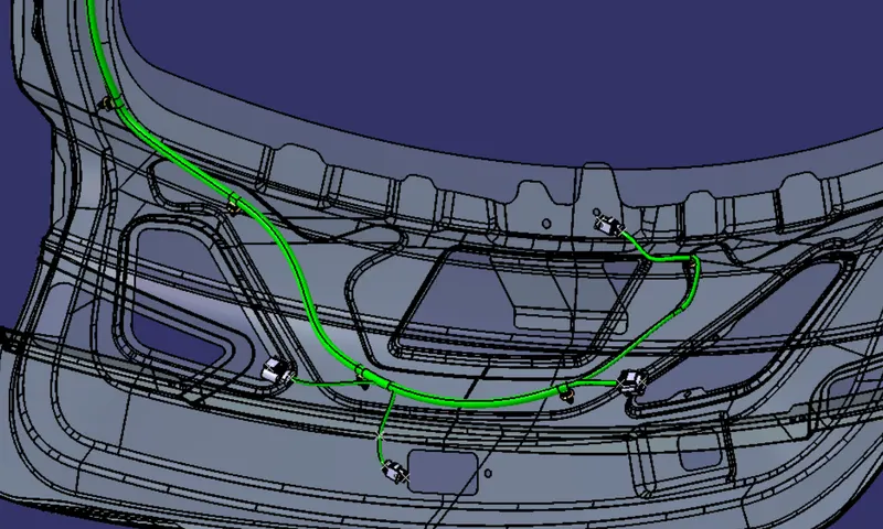
Protection Covering
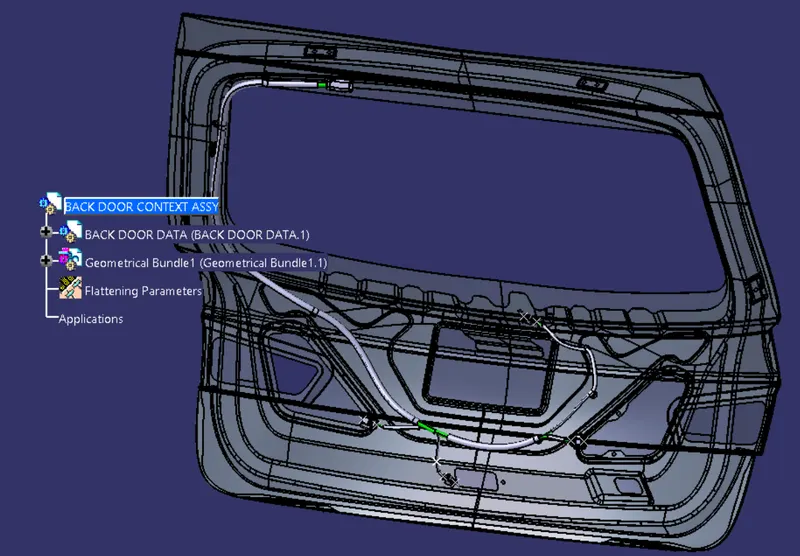
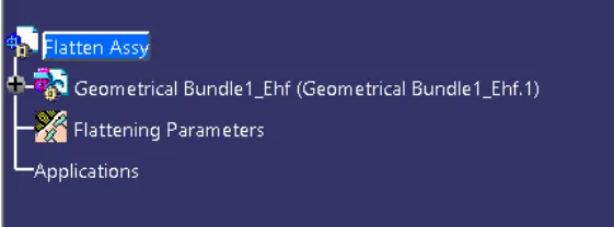
TREE STRUCTURE
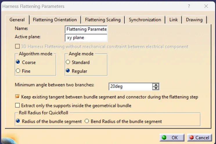
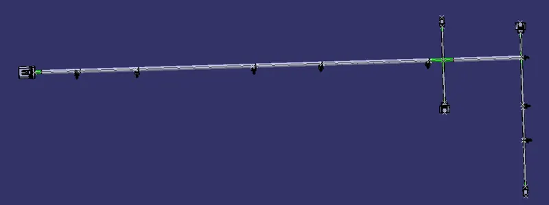
Harness Flattening
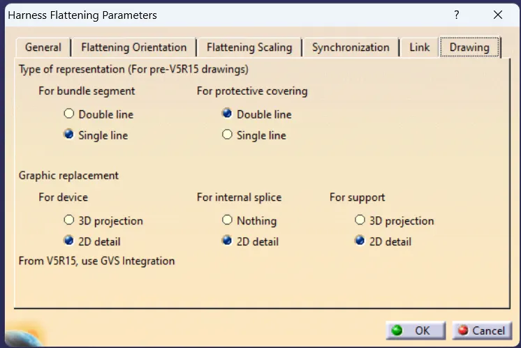
setting parameters
Extrat the harness assembly
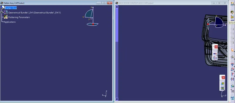
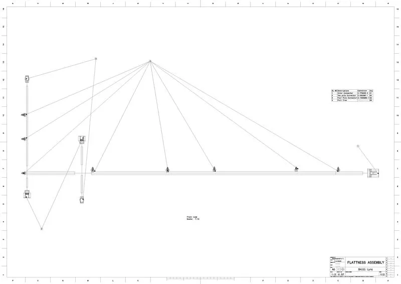
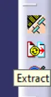
USING EXTRACT COMMAND WE NEED TO IMPORT THE HARNESS INTO THE FLATTEN ASSY
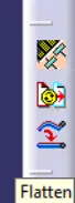
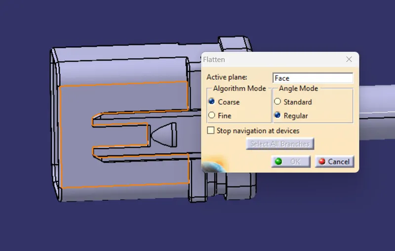
Now we need to Flatten the Harness Using Flatten Command
TREE STRUCTURE
DRAFTING
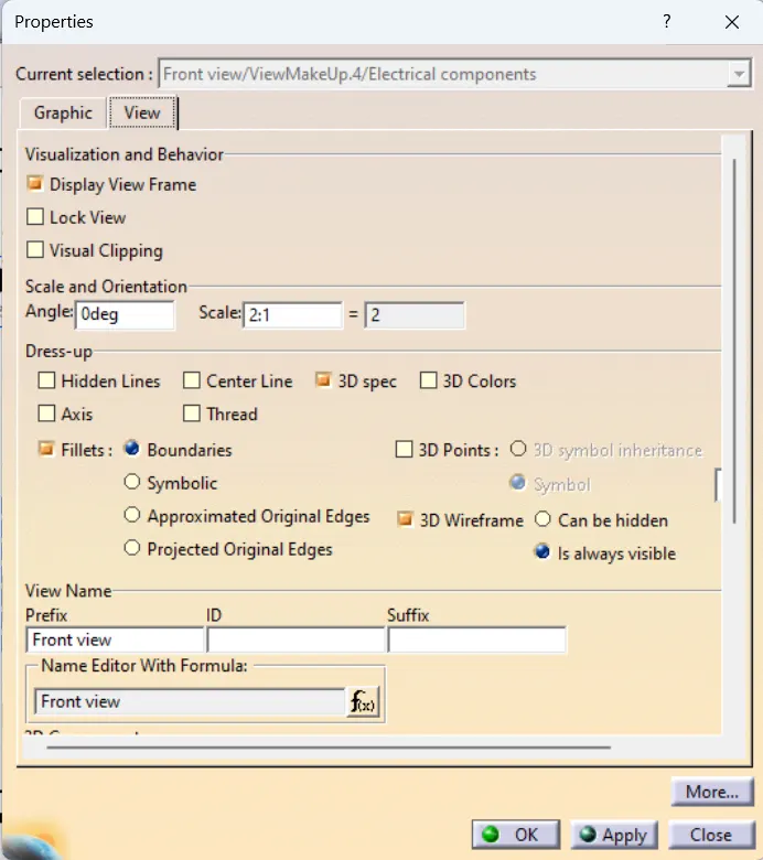
before draftig first we need to set the parameters as shown below
Properties that need to check after the views are inserted
Drawings