Week 8 - Challenge 2 - Switch Bezel Design
Week 8 - Challenge 2 - Switch Bezel Design
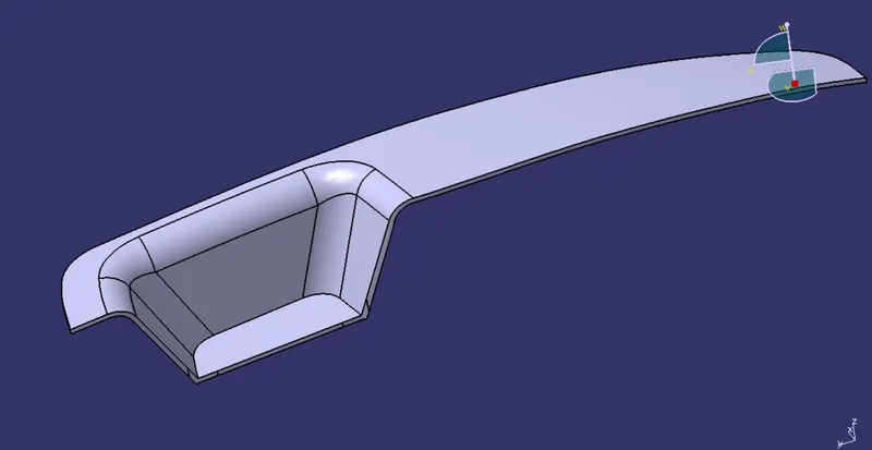
Aim:- To Create the Switch Bezel Plastic component through the given Class-A surface.
Objectives:
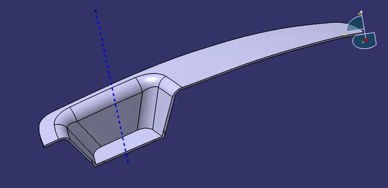
- Create Tooling axis with the Class A Surface.
- Check For the Draft by tooling axis.
- To Create Class B Surface.
- To Create Class C Surface.
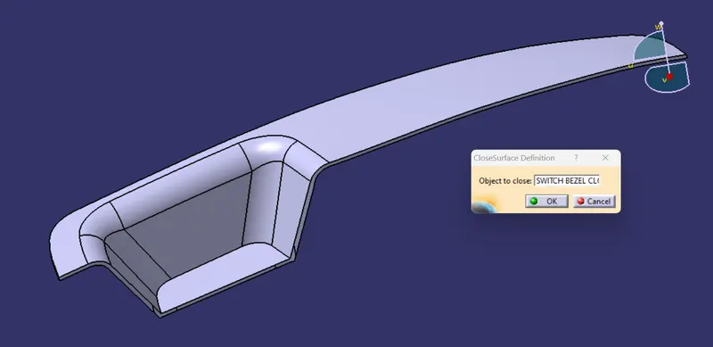
- To create model With Closed Surface Feature.
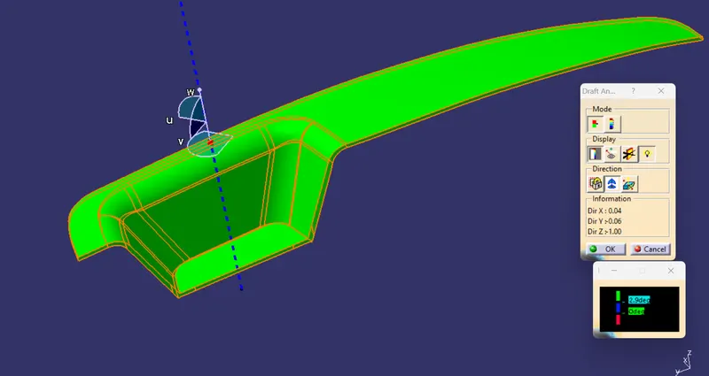
- And Draft Analysis for Final model.
CLASS A SURFACE
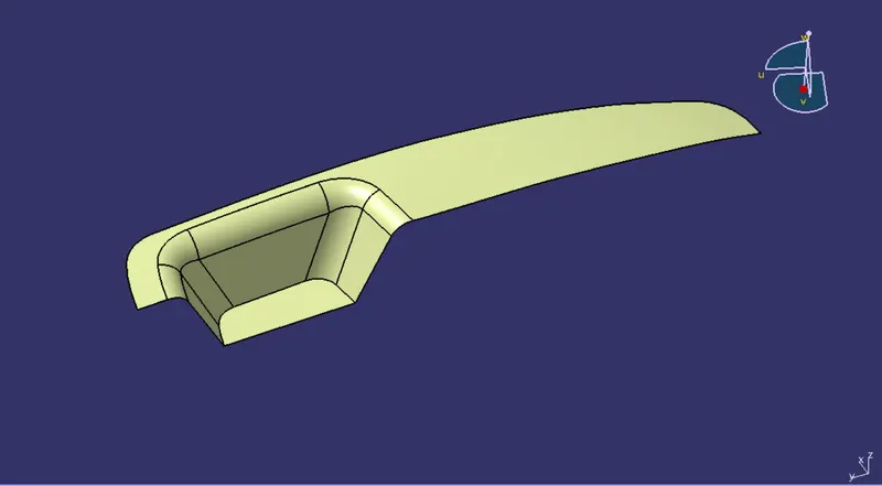
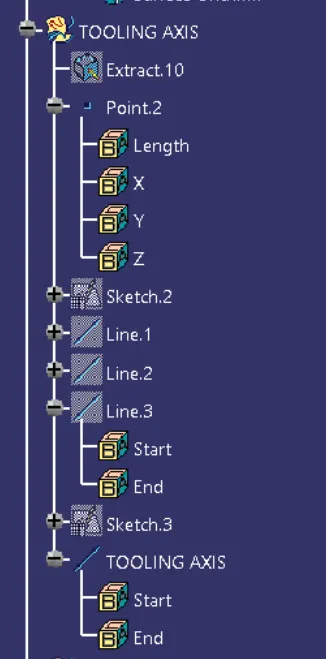
TOOLING AXIS
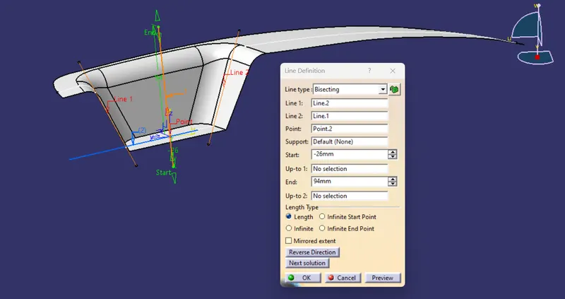
BISECTING LINE FOR TOOLING AXIS
Extract the base of the switch bezel and creating point over and an axis system on the point
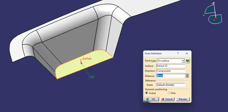
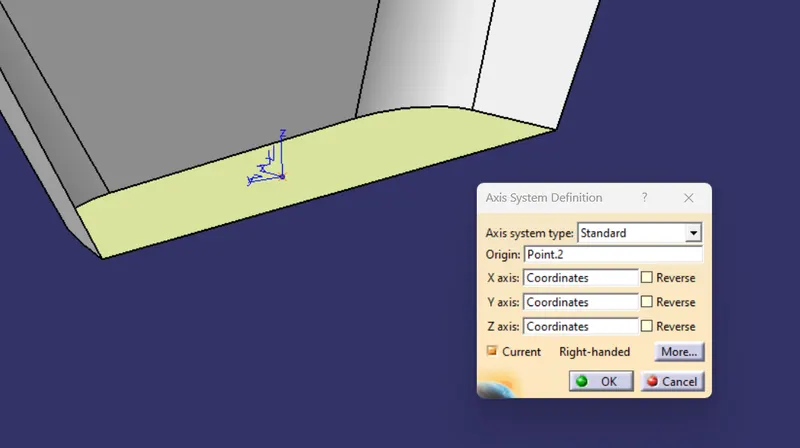
axis system
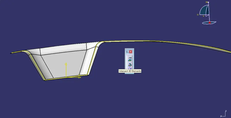
by using intersect 3d elements feature the sketch is created
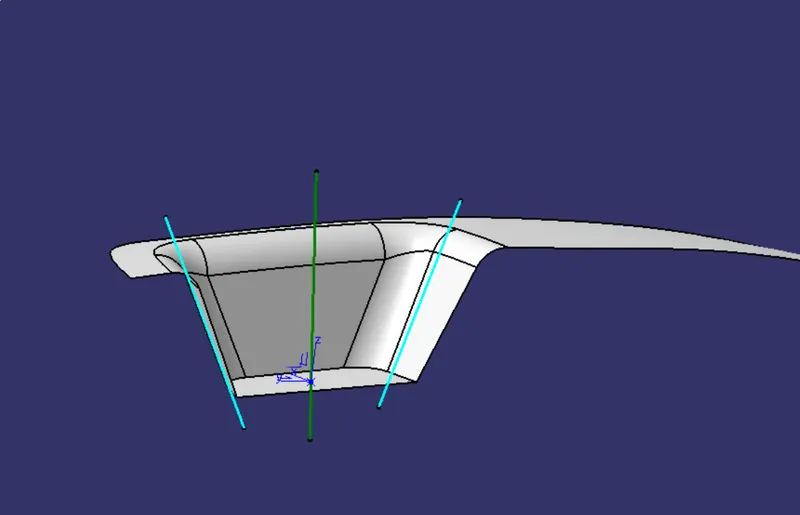
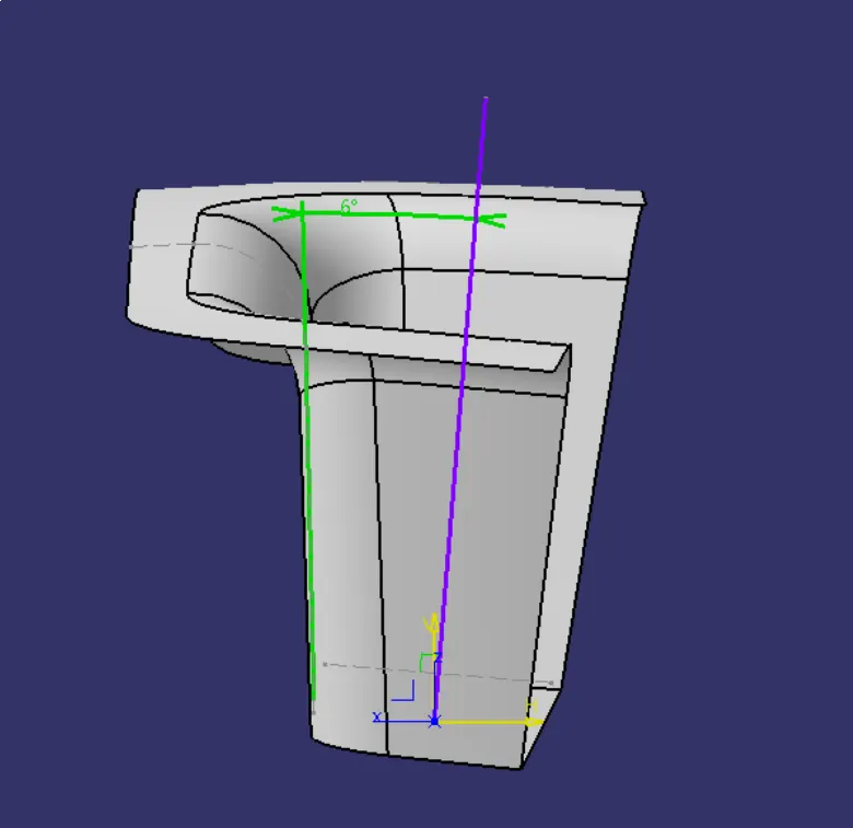
line is drawn at an 6 deg
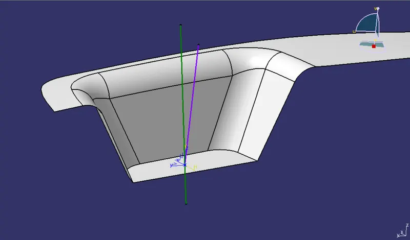
by using bisectig line method the tooling axis is created
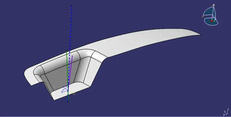
Final TOOLING AXIS
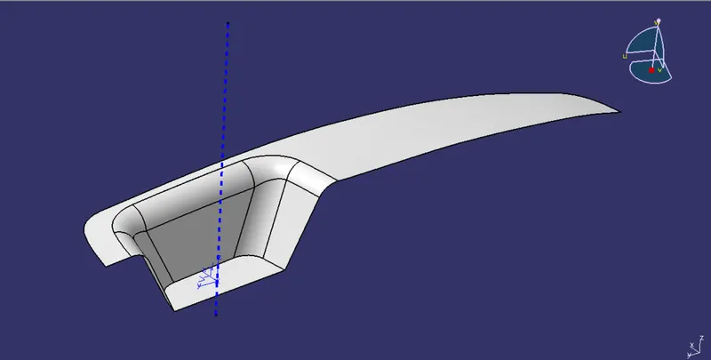
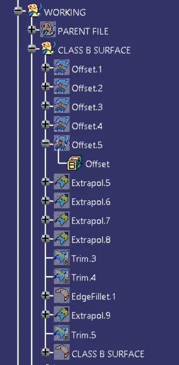
CLASS B SURFACE
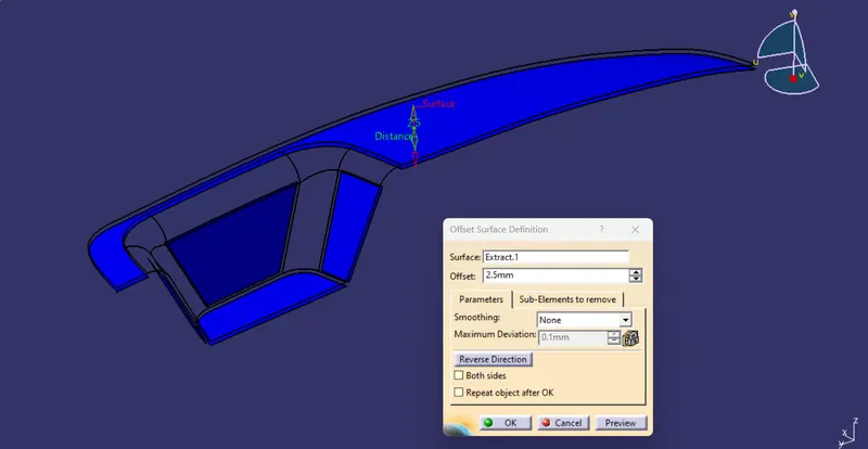
OFFSET
Taking Offset of Surfaces as shown in the figure which is highlited in blue colour and the offset distance is 2.5mm
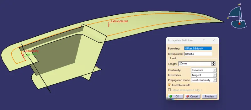
EXTRAPLOTE
extraplote the offset surface to 20mm as shown in the figure for further operations
TRIM
Trim is done to get requred shape as of Class A surface
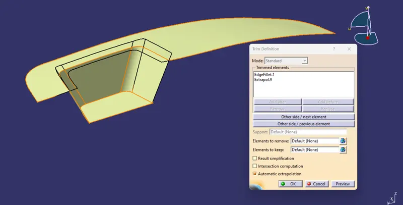
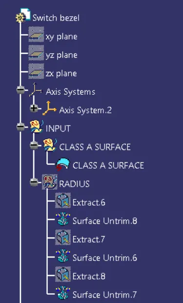
now we have calculate the Radius of the fillet which is given in the Class A surface for that we have to extract the faces of fillet and untrim them and then by measuring tool we have to calculate the radius as shown in the below figure
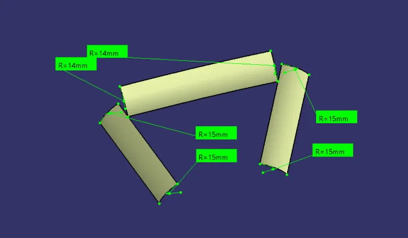
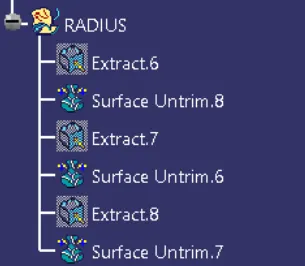
by the above figure we can conclude that the radius of the fillet is 15 and 14 mm so for the class B surface we have to minus the thickness of 2.5mm so we get uniform wall thickness in the body.
For 15 mm raidus the calculated radius in Class B surface will be 12.5 mm
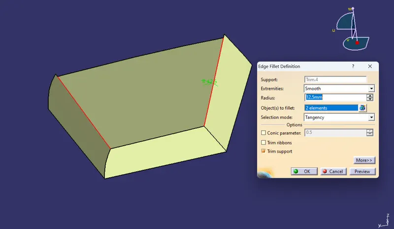
For 14 mm raidus the calculated radius in Class B surface will be 11.5 mm
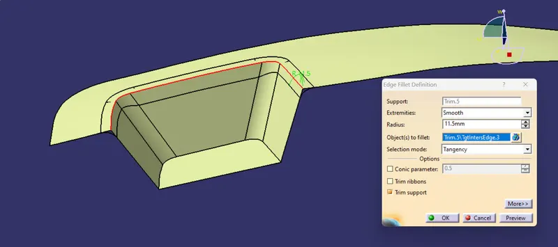
So we get Class B Surface
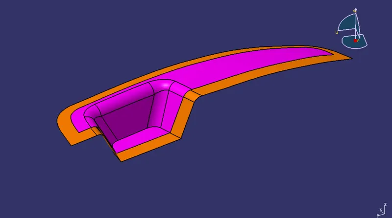
The surface which is in pink colour is CLASS A and in Orange is CLASS B surface
Creating Class C Surface
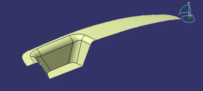
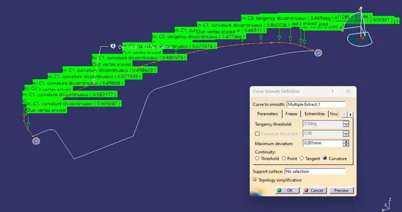
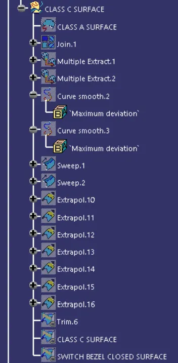
for Class B Surface We need to extract the edges of the Class A Surface by Multi Extract tool
SWEEP
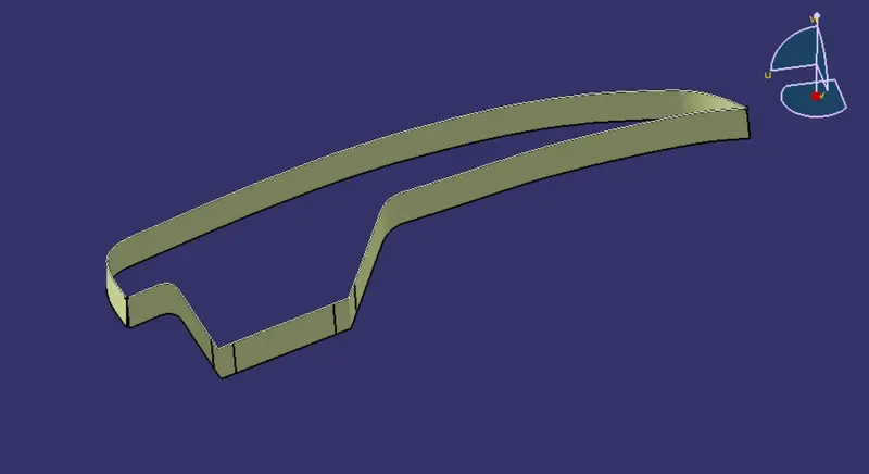
After Sweep we found there is some gap in the seep so we have to make it in single surface for further process
For that we use Extrplote and Trim feature
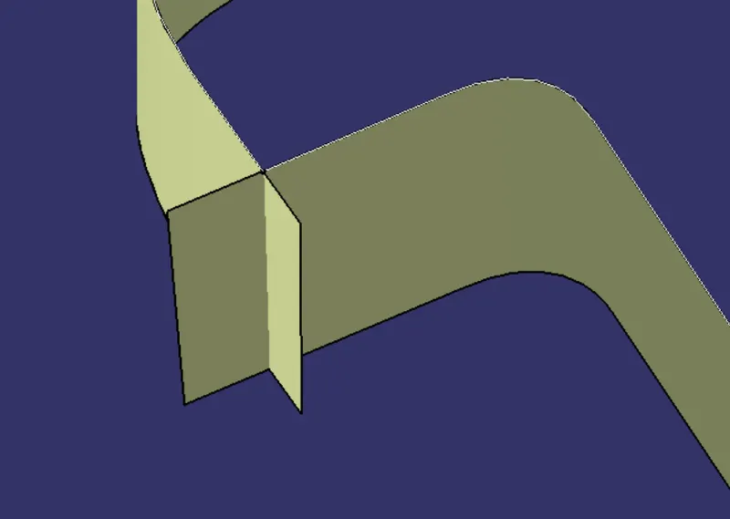
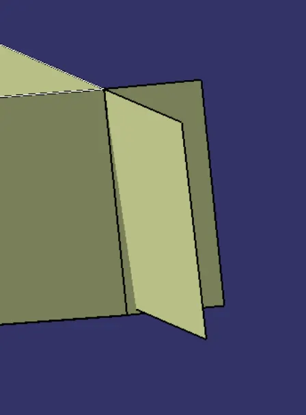
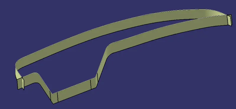
We also Extraplote the Class A Surface to make the surface simple
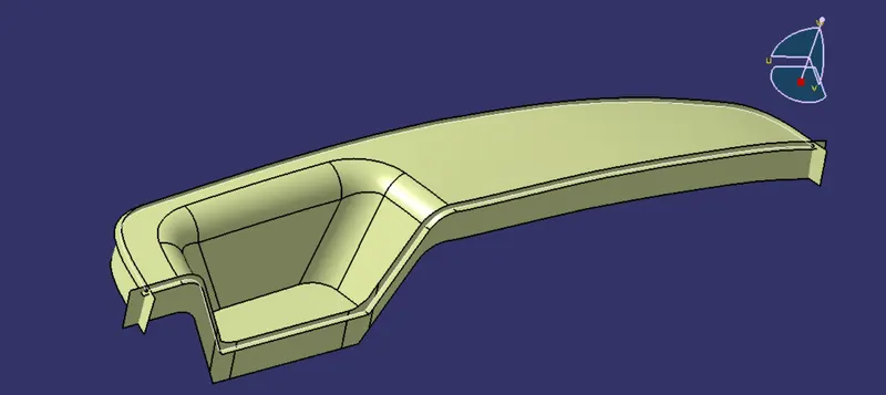
Final Class C Surface
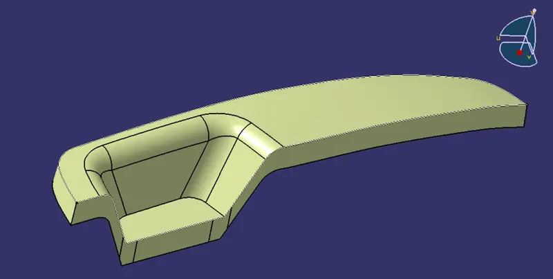
CLOSED SURFACE
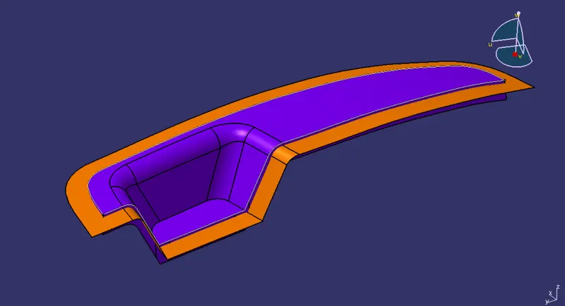
in the above figure we can see that the CLASS A and CLASS C are merged and it is represented in clour voilate colour
and the CLASS B Surface in Orange Colour.
Trim
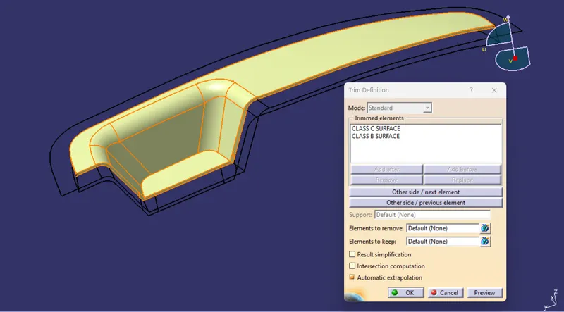
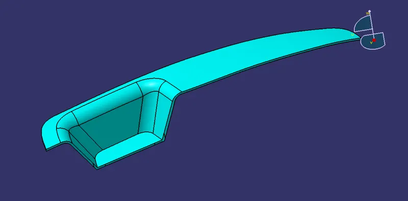
CLOSED SURFACE FEATURE FOR THICKNESS
DRAFT ANALYSIS
model after thickness
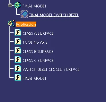
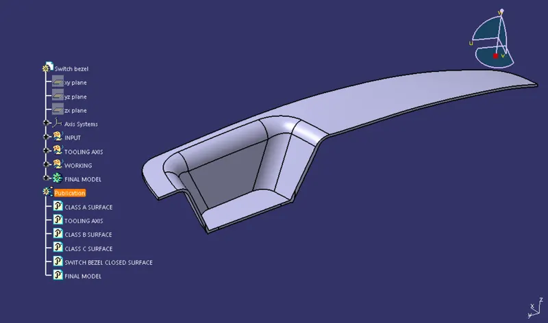
TREE STRUCTURE
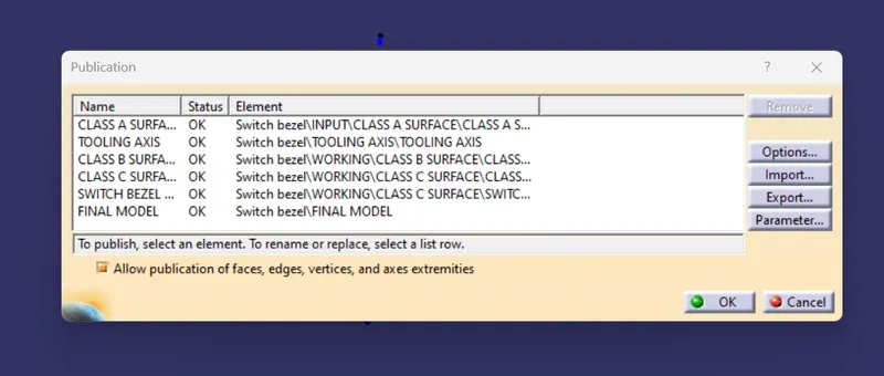
PUBLICATION
VIEWS
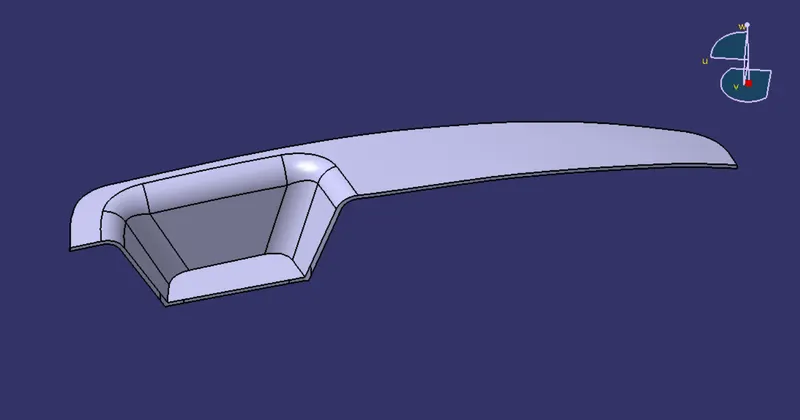
ISOMETRIC VIEW
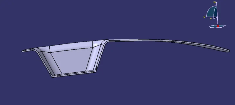
FRONT VIEW
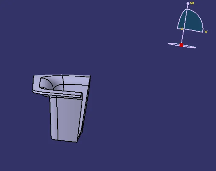
SIDE VIEW
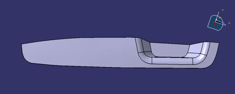
TOP VIEW
CONCLUSION
Switch bezel is created using Class A Surface.
CLASS B Surface is created.
CLASS C Surface is Created.
The thickness of 2.5mm is given to the Final closed surface using closed Surface Feature