Week 7- Base Unit Design Challenges 2
BASE UNIT DESIGN
AIM
Design a Base Unit for the units designed for the above challenges with all weldments for the given Car Panel.VDesign a Base Unit for the units designed for the above challenges with all weldments for the given Car Panel.
INTRODUCTION
BASE UNIT
A base unit is the unit designed to mount all other units like clamp unit, pin unit, rest unit etc. of the tool also other parts necessary for a tool like pneumatic valave box,trunking cable path will also be mounted on to a base unit.
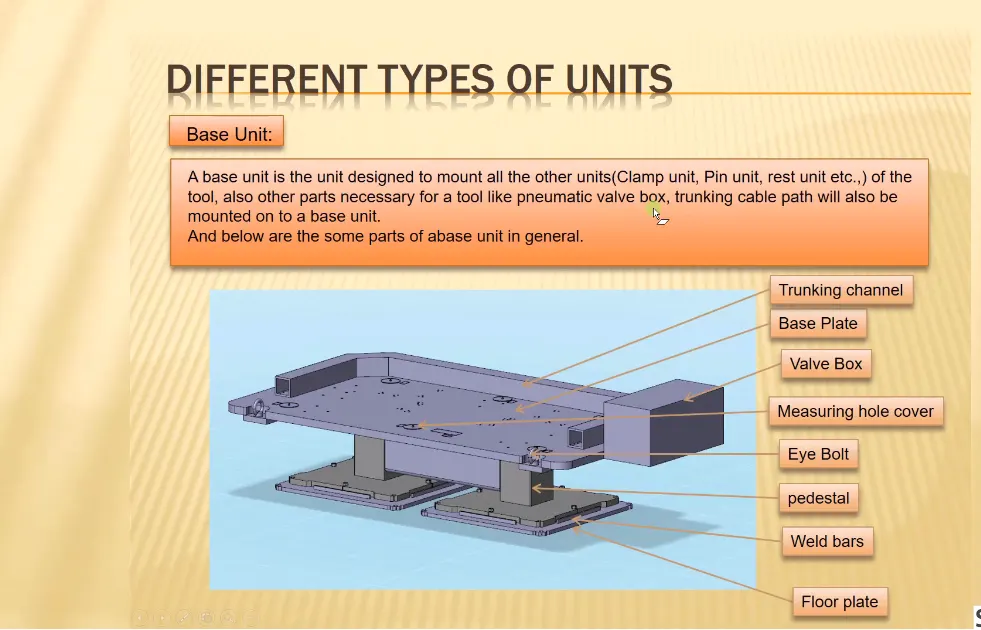
Typical parts of the Base Unit:
- Trunking channel
- Base plate
- Valve box
- Measuring hole cover
- Eye bolt
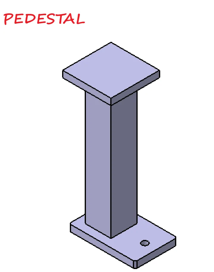
- Pedestal
- Weld bars
- Floor plate
FIXTURE: A fixture is a work holding device that holds support and locates the work piece in a desired position to perform any operation. This is the main purpose of the fixture that is to hold and support the work piece during machining operation and to provide repeatability, accuracy and interchangeability in the manufacturing of the products.
CLAMP UNIT IN BIW FIXTURE: A clamp unit is used to hold the panel at desired location and prevent it from unnecessary movements. A clamp plan is provided by the customer, which helps us to design the clamp unit as it consists of the location of clamping. But to understand how the clamp unit successfully restricts the movement of the panel we must understand 3-2-1 principle.
CLAMP UNIT:
- A clamp unit is a unit designed to clamp/hold the car panel with NC blocks / Mylars / Rest by using a pneumatic cylinder. Clamp arm, finger, rest/backup, L-block, shims, Risers, Pneumatic cylinders are the typical parts of clamp unit.
- Clamping force should be considered while designing a clamp unit.
- Mostly to avoid excess part, to reduce the weight & reduce the cost of the fixture the rest unit is combined with the clamp unit.
- The below figure shows the combination of the clamps & rest unit which have been designed in this project by considering the basic principles of clap & rest unit design.
TYPES OF CLAMP UNIT:
- Power Clamp unit.
- Swivel cylinder clamp unit.
In this project, I have used the Swivel clamp unit to design.
3-2-1 PRINCIPLE
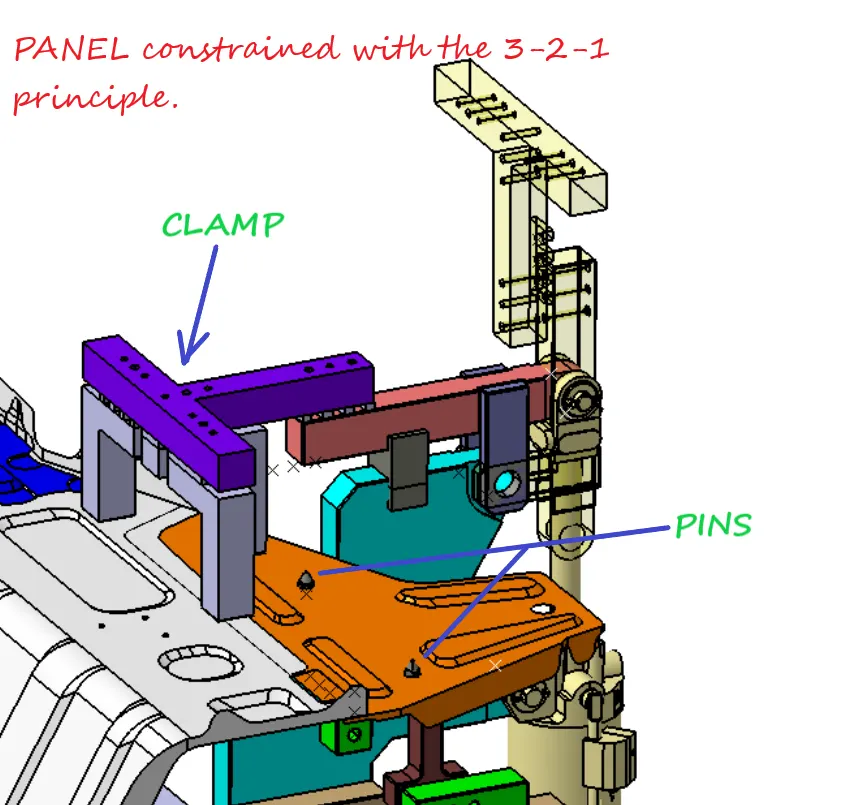
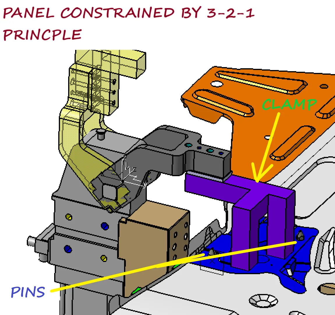
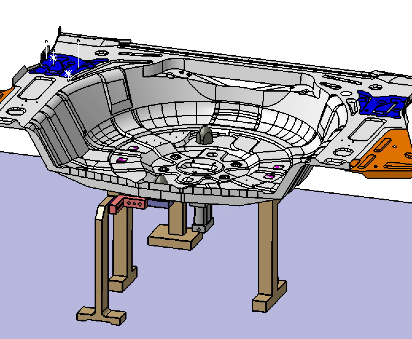
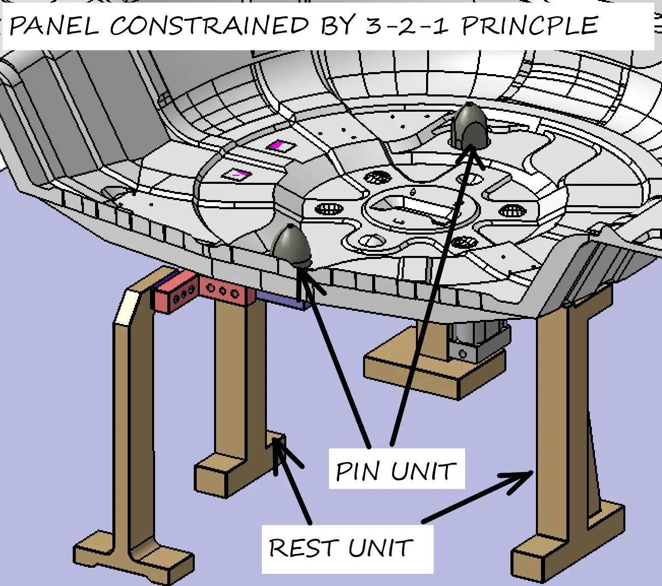
The 3-2-1 Principle states that the six locators are sufficient to restrict the required degree of freedom of any work piece. In this, motion is restricted using clamps and locators. A three-pin base can restrict five motions and six pins restrict nine motions.
Let us understand this in detail. When any work piece is not clamped or held, it can move or rotate in any direction and along any axis. We can list its movements as:
- Translational motion along x-axis.
- Translational motion along y-axis.
- Translational motion along z-axis.
- Rotational motion along x-axis.
- Rotational motion along y-axis.
- Rotational motion along y-axis.
FIG. DEGREES OF FREEDOM
These are not just 6 but 12 as its motion will be along positive and negative directions and along clockwise and counter clockwise direction. But if we were to perform any operation on that work piece we must restrict the movements in order to perform the task without any mistakes. This can be achieved by 3-2-1 principle. In 3-2-1 principle we make use of locating pins in the given order to fix it on a fixture:
- 3 pins are located on the bottom side of the component. These pins constrain the translational motion of the body in z direction and rotational motion along x-axis and y-axis. Thus 3 degrees are restricted. But the body still can rotate along z-axis and translate in x-axis and y-axis.
- 2 pins are located on the back side of the component. These pins constrain the translational motion along x-axis and rotational motion along z-axis. Thus we have constrained 5 degrees in total. But translation along y-axis is still possible.
- 1 pin located on the adjacent side of the 2 pins we can constrain the last degree that is translation along y-axis.
FIG. LOCATING PINS
In clamp unit, we use clamping Mylar and Rest Mylar to locate the panel. Here we are doing following things:
- Restricting the upward and downward motion that is movement along z-axis.
- Restricting clockwise and counter clockwise rotation along x-axis.
- Restricting clockwise and counter clockwise rotation along y-axis.
Thus out of 6, we are restricting 3 degrees of freedom when we clamp the panel. Similarly, when we locate the panel with locating pins we:
- Restrict the translational movement along x-axis.
- Restrict the translational movement along y-axis.
- Restrict the rotational movement along x-axis.
- Restrict the rotational movement along y-axis.
MATERIAL USED:
In general, the materials used for Mylars, Clamp arm, shims, shim block, blades & risers are:
- Mylars: UHMW, Nylon66, PP, Teflon (Poly tetra fluor ethylene (PTFE)). Materials of clamp block and rest block to be decided as per the A class panel or B
- Clamp Arm: SAE 4140 or SAE 1045.
- Shims/spacer: S.A.E. 1010 CRS FULL HARD, COLD ROLLED STRIP STEEL S.A.E. 1010 FULL HARD, S.A.E. 1020 HRS, etc.
- shim block: STEEL ASTM A- 36, NM stainless, STEEL ASTM A-36, SS type 3030 or 304,
- Blade: STEEL ASTM A-36,
- Riser: STEEL ASTM A- 36,
HARDNESS:
In general, the hardness of the materials for pins, pin retainers, shims, shim block, blades & risers are 55 – 60 HRC to a depth of 0.5 -0.7mm after grinding.
SURFACE FINISH:
In general, the hardness of material for Mylars, Clamp arm, shims, shims block, blades & risers are:
- Clamp arm: Munsell No.3.75YR6/14 safety orange
- shims/spacer: BLACK OXIDE FINISH (SURFACE TO BE FLATE PARALLEL TO WITHIN 0.015 T.I.R.
- Riser: SURFACES TO BE FLAT, PARALLEL & PERPENDICULAR TO WITHIN 0.015 T.I.R.
Points need to account while designing a Base unit
- Working height: It depends on the nature of the manual or robotic welding fixture. for manual fixture we need to consider the working height 850-1100mm depending upon the height of the worker stanadard of a specific country will apply( in few countries human height is higher or lower eg.(US, Japan). If base unit structure is made with base plate having tubular structure welded below it, we can reach to height 100mm to 250mm. In this case to reach the working working height we need to provide additional some leg structure which may have to and bottom plate welded to the tube.
- As designer it is important to know how big base plate or bigger base welded structure will be handled during the fabrication and handling process. Special care need to take care of flatness if the base size is very long.
- Depending upon the weight eyebolt size is selected for lifting holes on the base plate. Generally four eye bolt provision is made. You also need to select the location of eye bolt considering the rope/belt used while shifting the structure or complete fixture are not damaging any units (rest,clamp or location units) nearby.
- Only base plate or welded structure. Depending upon the componenet size and weight of the total units you can decide whether you need a fabricated base or just plate. Mostly fabricated bases are used made of square or rectangualr tube with the plate.
- Most of the OEM makes 4 dowel holes at 4 corner and put small aluminium plate marking x,y and z coordinates of dowel holes. If the base length is too long few OEM's follow the methodology of having holes at 500mm distance.
- The best unit of the fixyure must be strong enough so that deflection of the fixture is as minimum as possible. The deflection of a fixture is caused because of forces of welding,clamping of the work piece.
- The base unit of the fixture should have the mass to prevent vibration and chatter.
- The base unit may be built from simple section so that other units may be fastened with screw or welded necessary. Those parts of the fixture that remain permanently with the fixture may be welded. Those parts that need frequent changing may be held with screws.
- The base unit should be paralled to the floor, to adjust this there should be provision of the height adjusting mechanism.
BASE PLATE DESIGN
- A base plate size should cover all the units with its outer periphery including opening.
- A base plate is preferred to be designed with respect to BCS coordinates.
- A base plate should be drilled with datum holes/measuring holes in line with a pitch of 1000mm in general.
- Number of datum holes is depend on the size of the boxplate.
- Datum hole should be drilled at nominal value of coordinates and in terms of 50 & 100 in general Ex. X= 100, Y=-600, Z=250.
- Datum holes should be drilled with diameter 100mm away from the other unit.
- Datum holes should be covered with cover plates.
- Working height depends on the nature of the manual or robotic welding fixture. For manual fixture we need to consider the working height 850-1100 mm, depending upon the working height of the worker standard of specific country will apply.
- If base structure is made with base plate having tubular structure welded below it we can reach to height 100 mm to ~250 mm. In this case to reach the working welding height we need to provide additional some leg structure which may have top and plate plate welded to tube.
The base unit of fixture must be strong enough so that deflection of the fixture should be minimum. This deflection of fixture is caused because of forces of welding, clamping of the workpiece. The Base unit of the fixture should have the mass to prevent vibration and chatter.
Base unit may be built from simple sections so that other units may be fastened with screws or welded whenever necessary. Those parts of the fixture that remain permanently with the fixture may be welded. Those parts that need frequent changing may be held with the screws.
The base unit should cover all the units with its outer periphery including opening. The base unit should be parallel to the floor, To adjust this there should be the provision of height adjusting mechanism.
BASE PLATE DESIGN
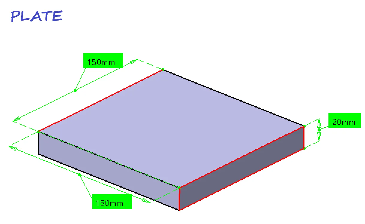
Base Plate dimension
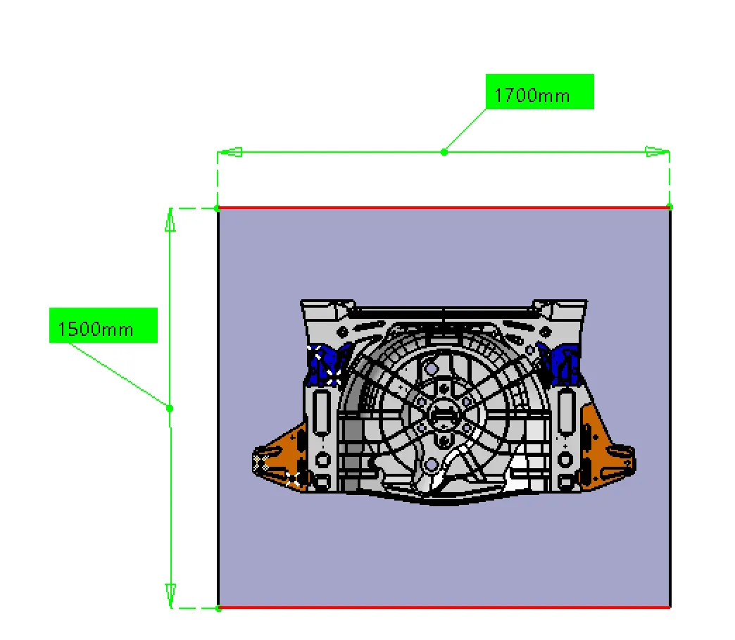
so by considering the above dimensions we are going to create the stand
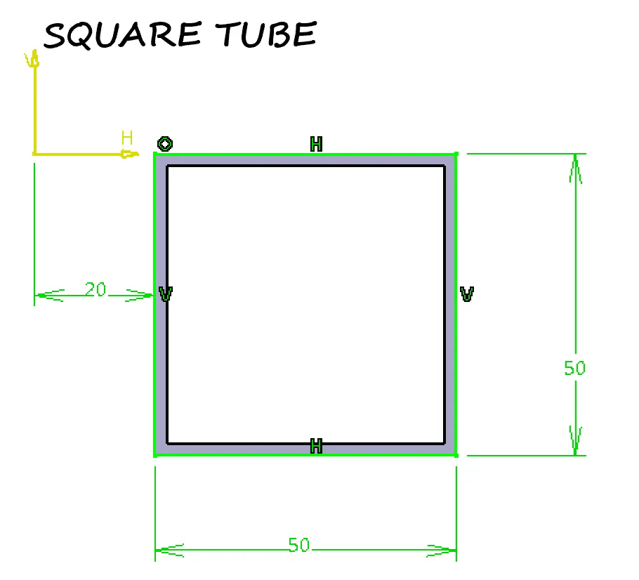
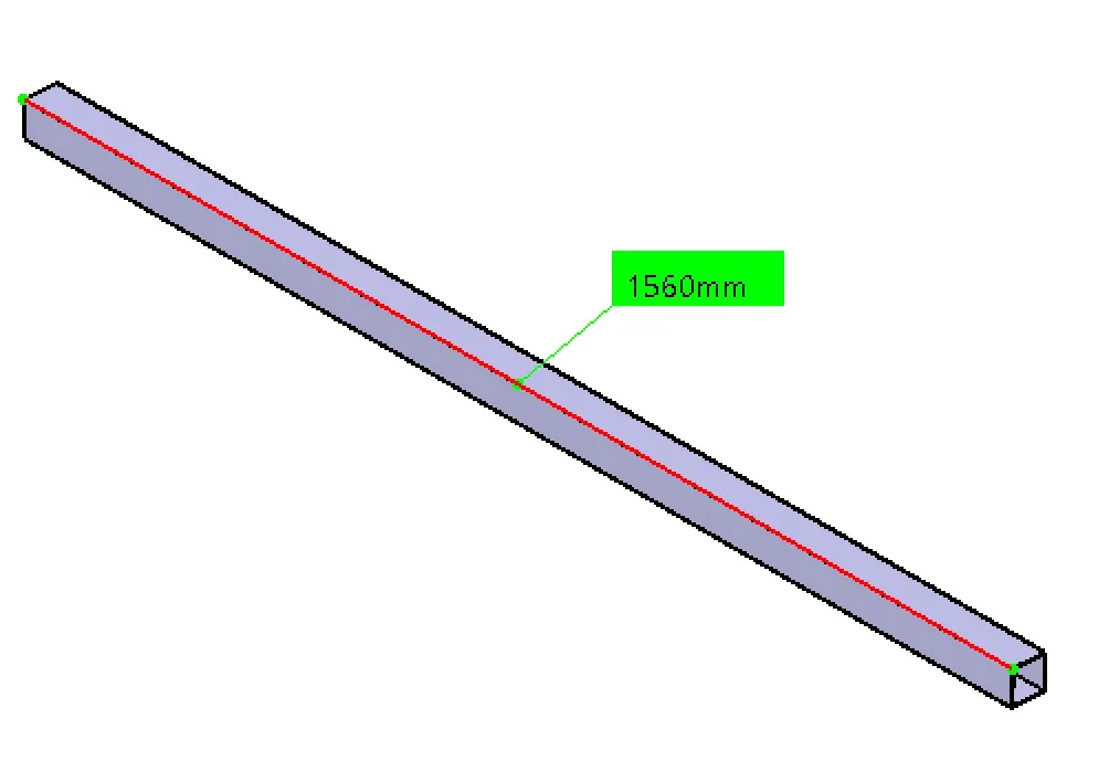
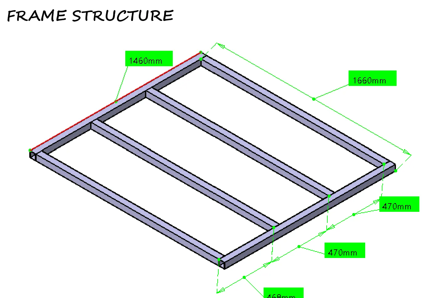
FRAME DESIGN
SQUARE TUBE
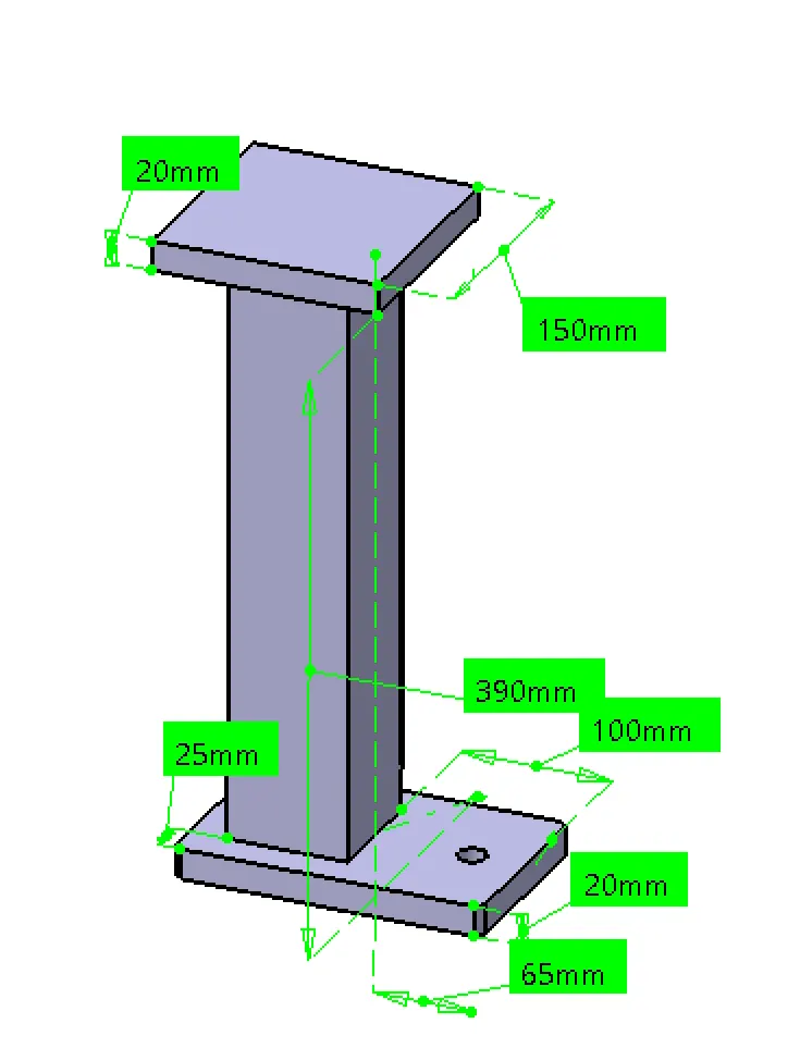
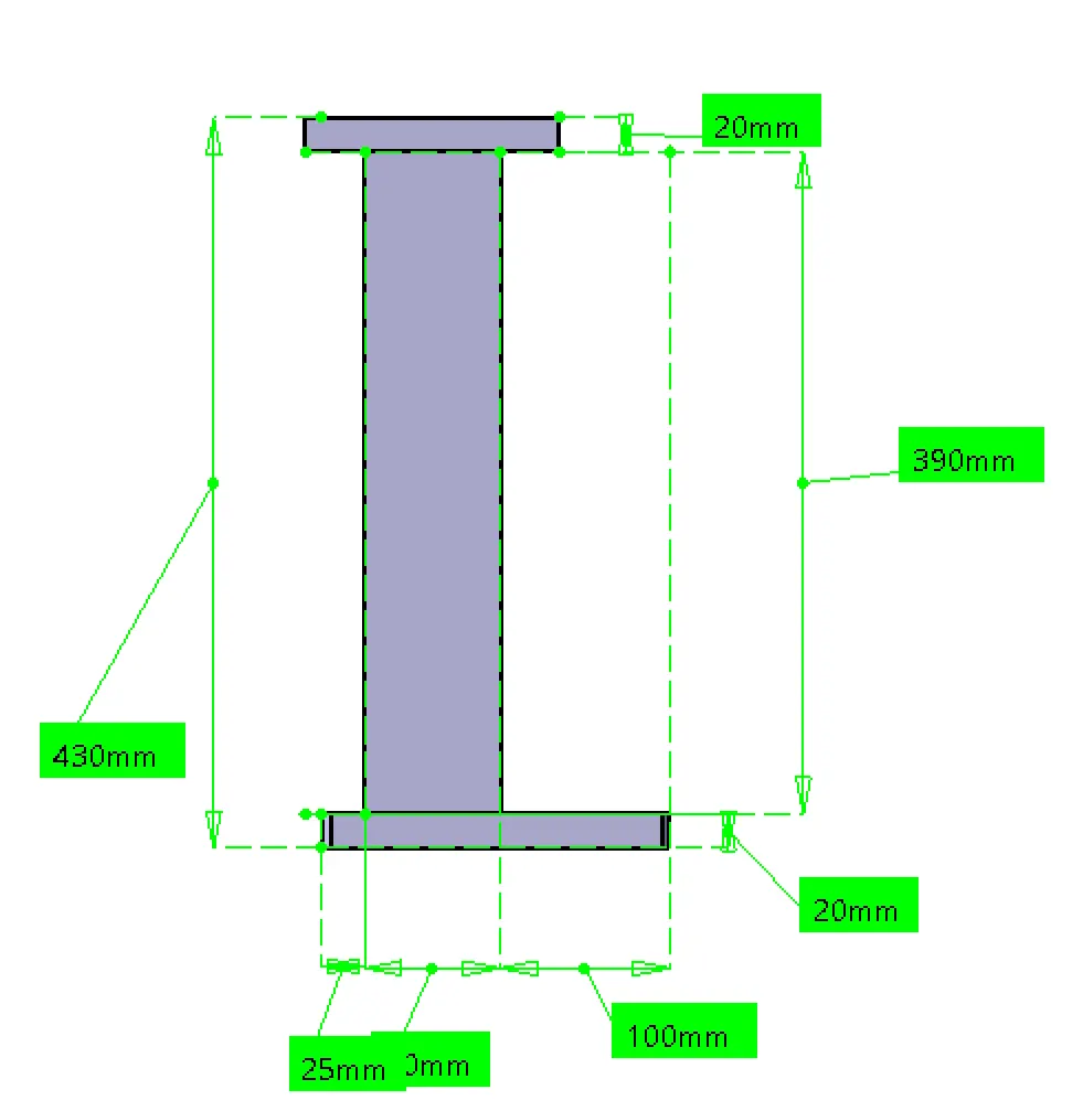
PEDESTAL DESIGN
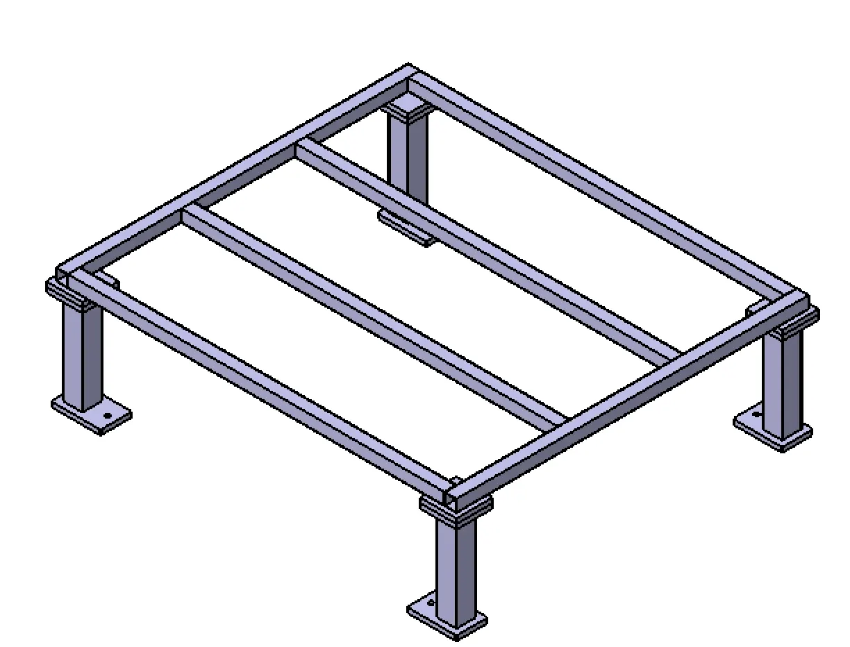
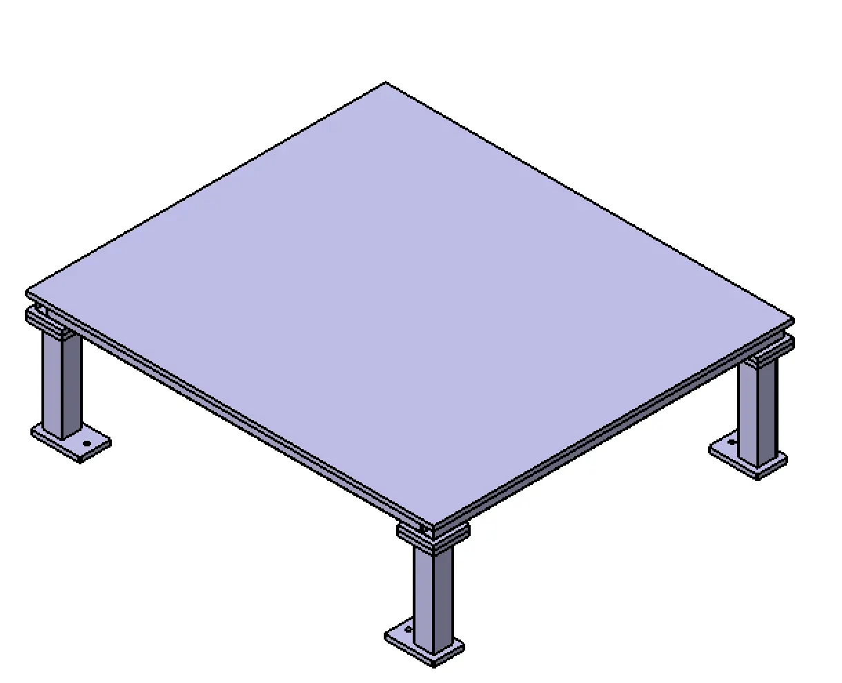
BASE UNIT
WITH COMPONENT
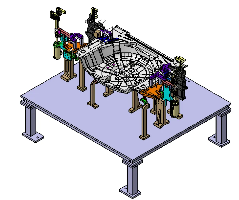
WITHOUT COMPONENT
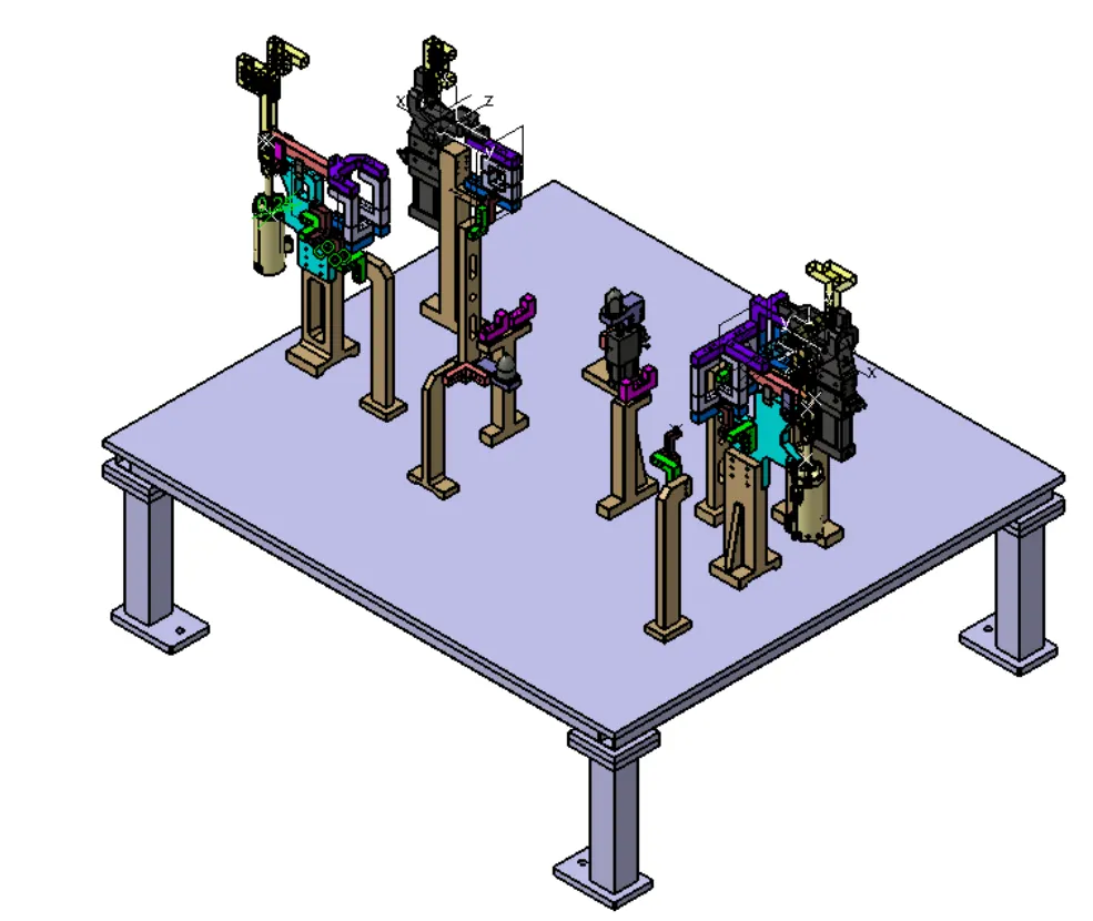
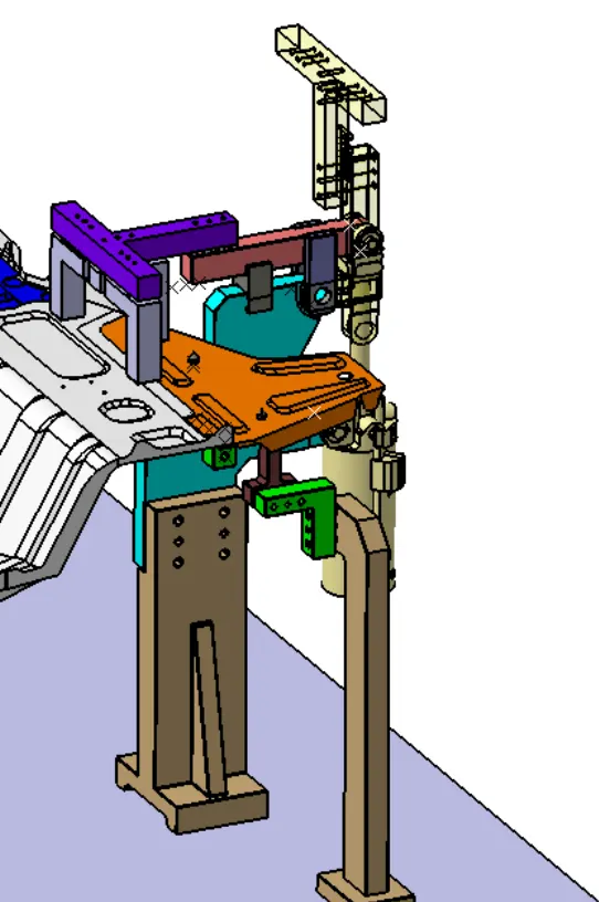
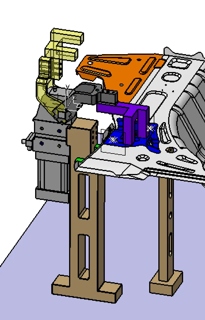
3-2-1 PRINCIPLE
PANEL 01
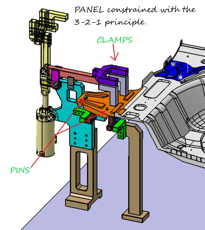
PANEL 02
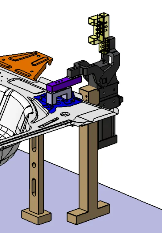
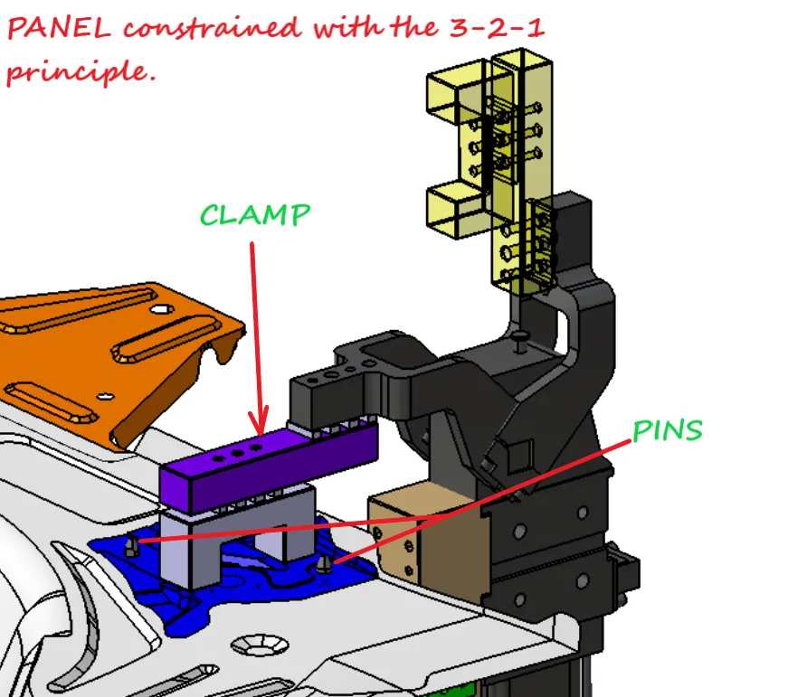
PANEL 03
PANEL 04
PANEL 05
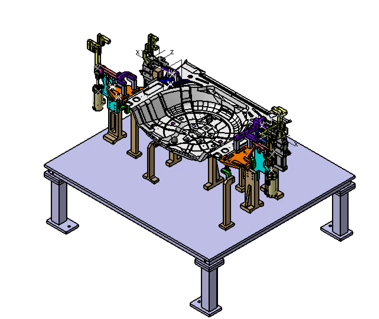
ISOMETRIC VIEW
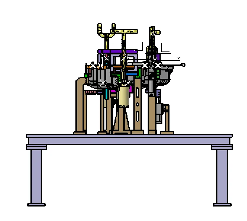
FRONT VIEW
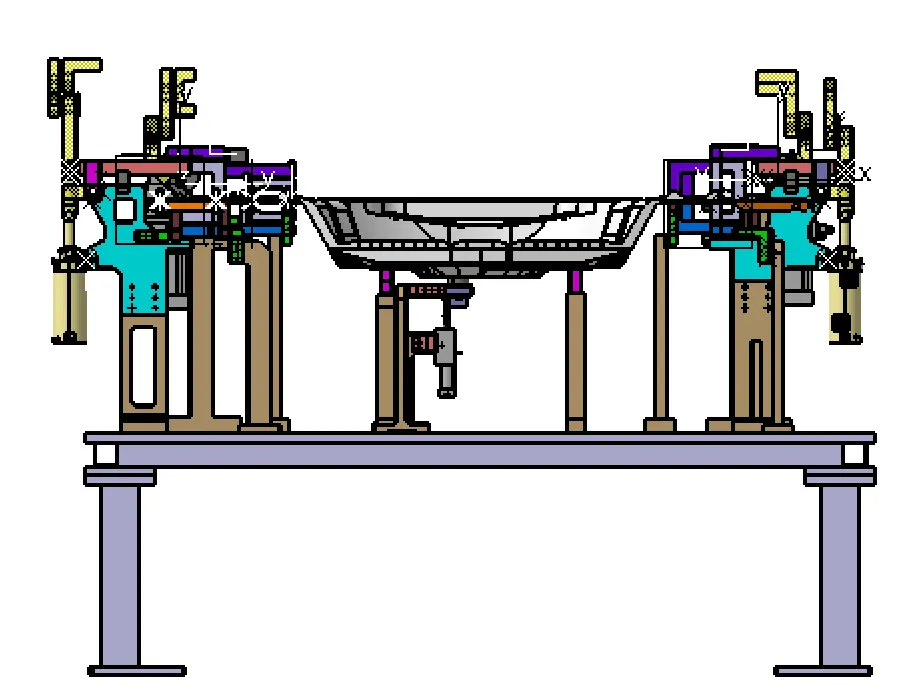
SIDE VIEW
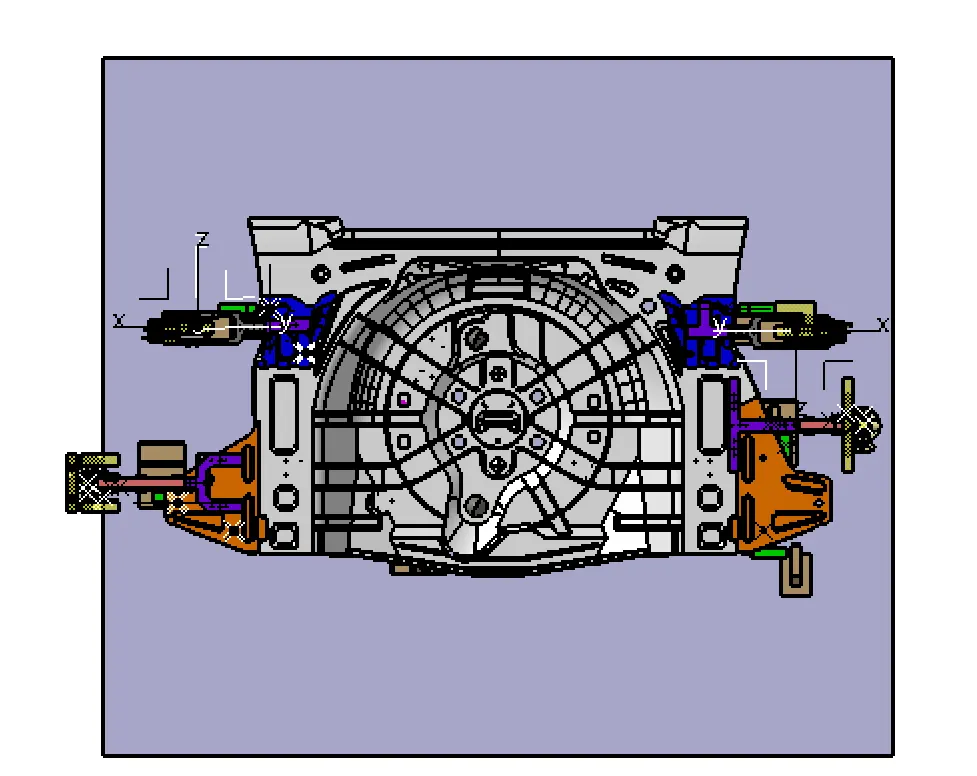
TOP VIEW
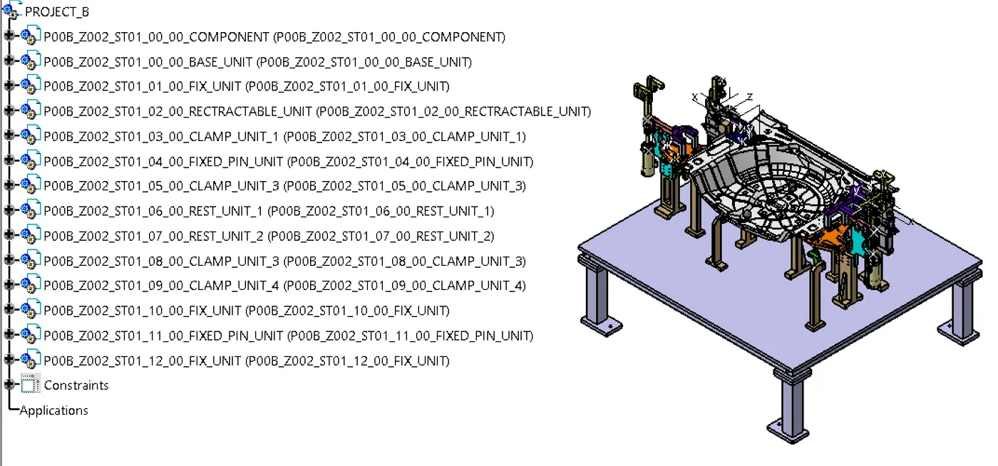
TREE STRUCTURE
CONCLUSION
- Base unit is designed by considering standards
- All the panels are Constrained using 3-2-1 principle