Wiring harness routing & packaging Rules Week 3 Challenge
SUPPORT DEFINITION
P Clamp
link: https://drive.google.com/file/d/1cL9NiCnMl1I0SGlRESUZwdjSP5_9eAlb/view?usp=sharing
P Clamos are used to clamp the Wiring Harness by providing rubber insulation in order to protect from Electrical Short circuits and damages
In clips there are 2 entry faces and 2 exit faces from Right to Left and from Left to Right.
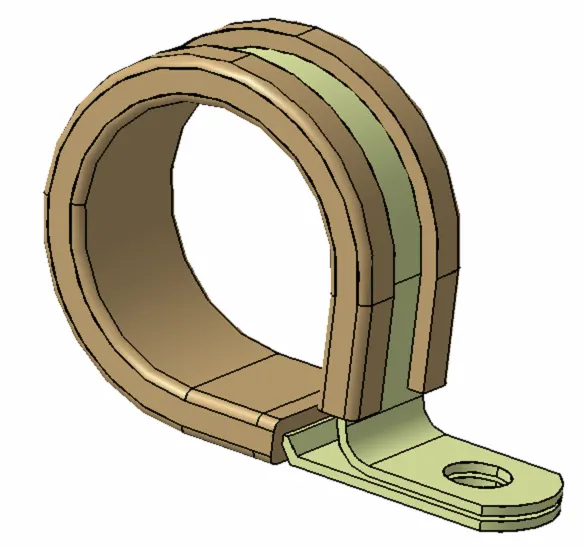
Geometrical definations
1. Point creation
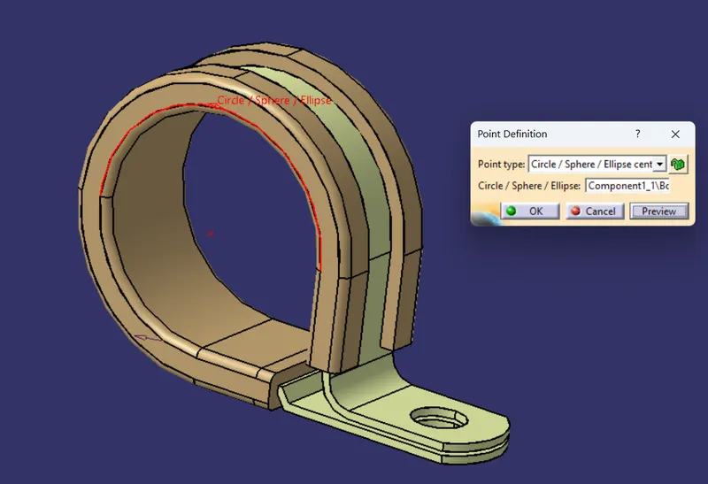
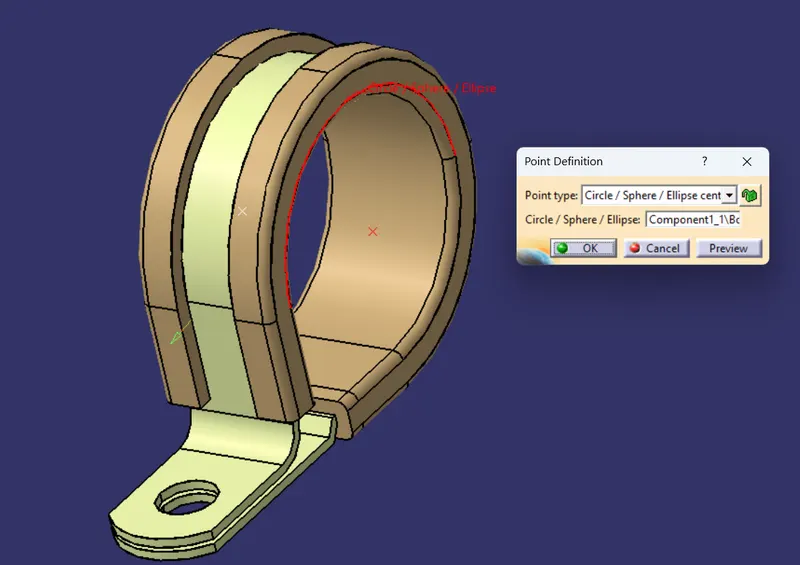
Plane Creation
Plane 01
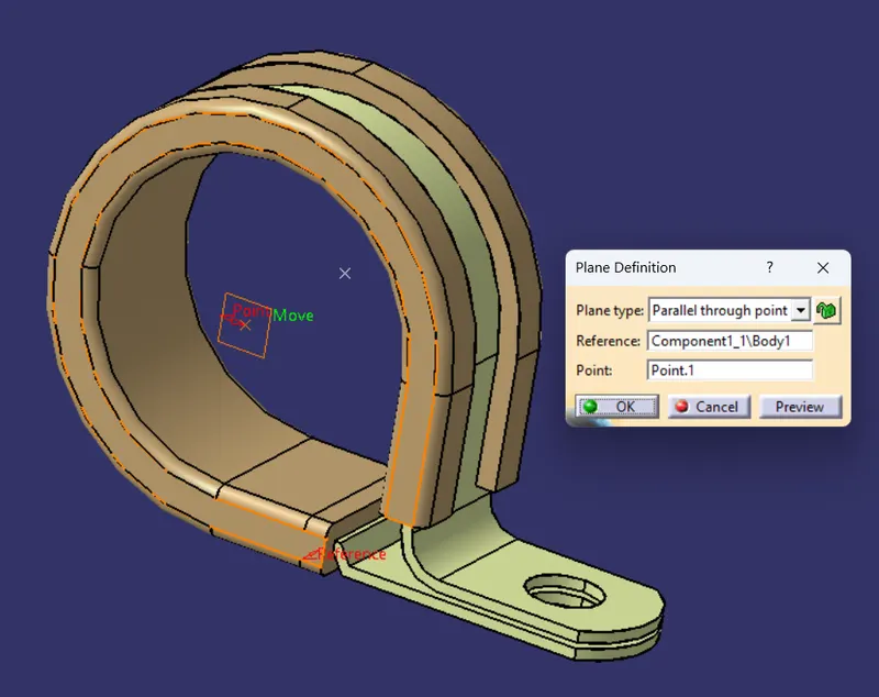
Plane 02
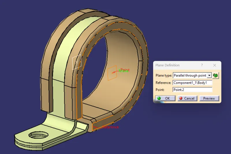
Base Plane
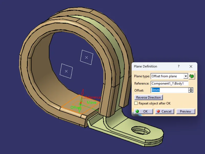
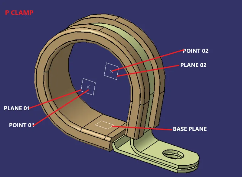
After creating all required geometrical properties like point and plane go to electrical part workbench to create Part as Electrical component
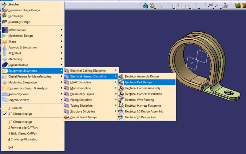
Define P Clamp as Electrical component
we known that P Clamp is a Supporting Component use to tie the Wiring Harness Rigidly in Vehicles like Trucks ,Off Road vehicles so we need to define P Clamp as Support
SUPPORT DEFINATION
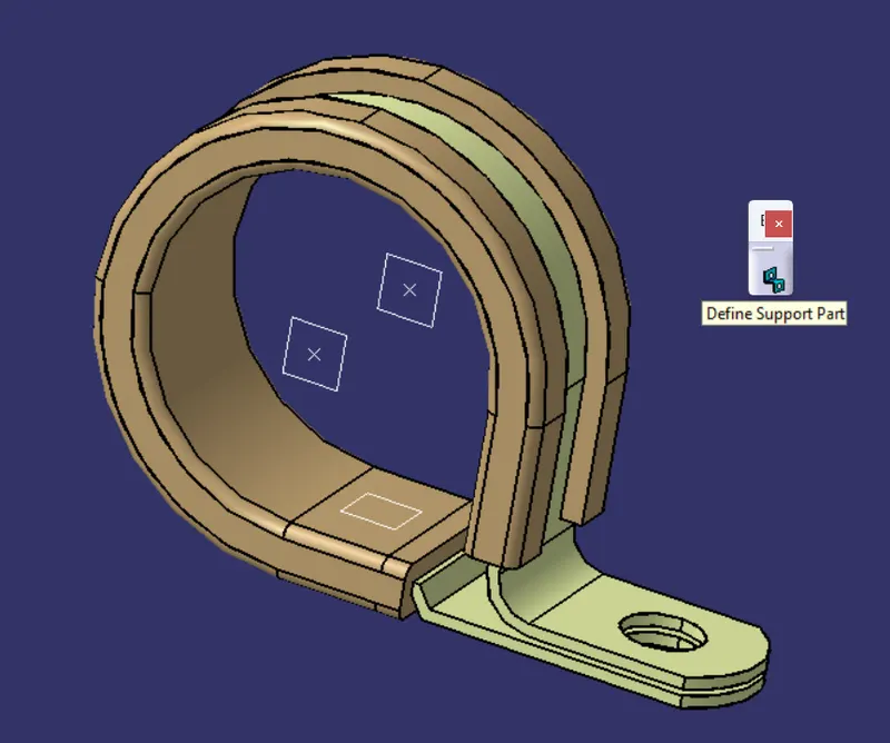
select the command as shown in fig to define as support
Support Definition
First Entry and Exit Plane Definition
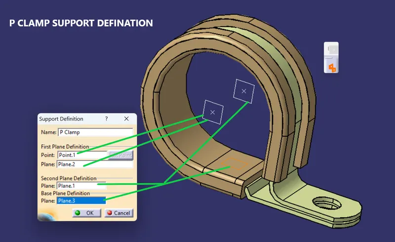
in this case the Entry Point will be First Plane Defination and Exit will be Second Plane Defination.
Second Entry and Exit Plane Definition
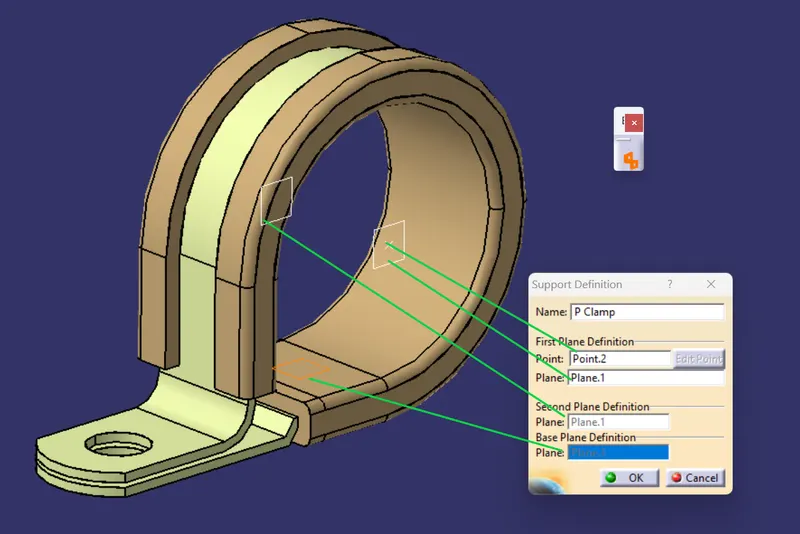
P clamp is defined as Support Clip
Properties added
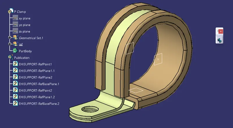
BACKSHELL DEFINITION
Download the Part using links provided
Link:https://www.te.com/usa-en/product-1738312-1.html
BACK SHELL
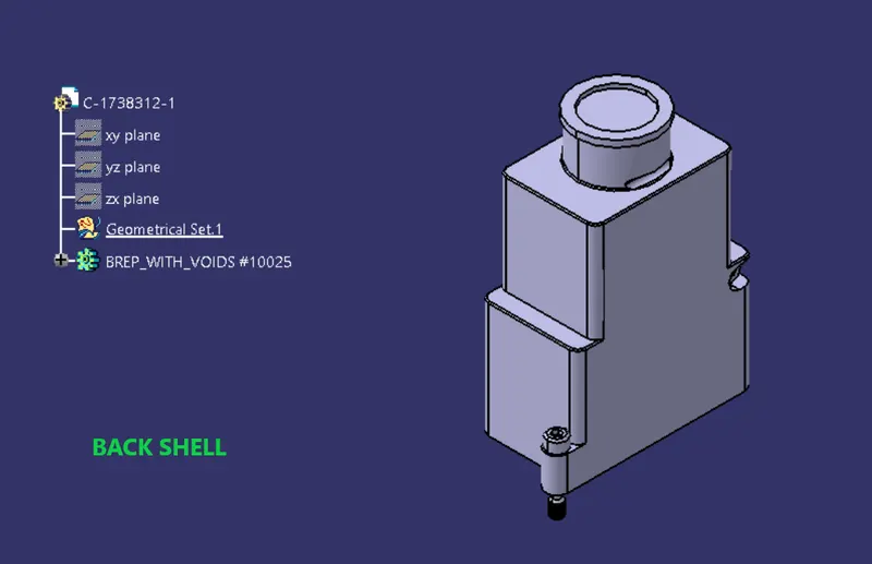
to define the above part as backshell we require geometric features like point and axis system
Create Geometical features
Point creation
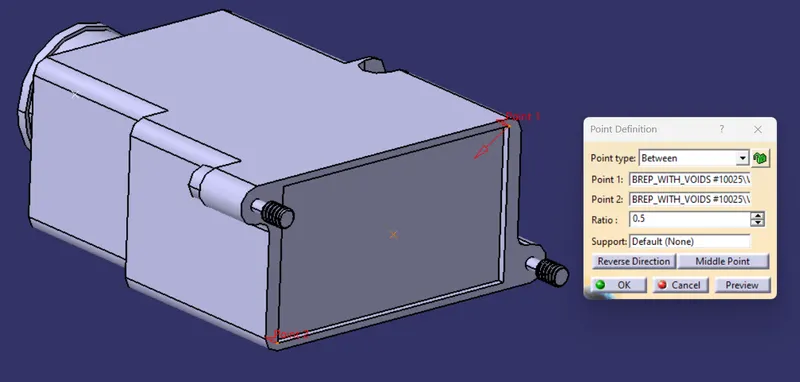
create point by using between option
select the edge points as shown below
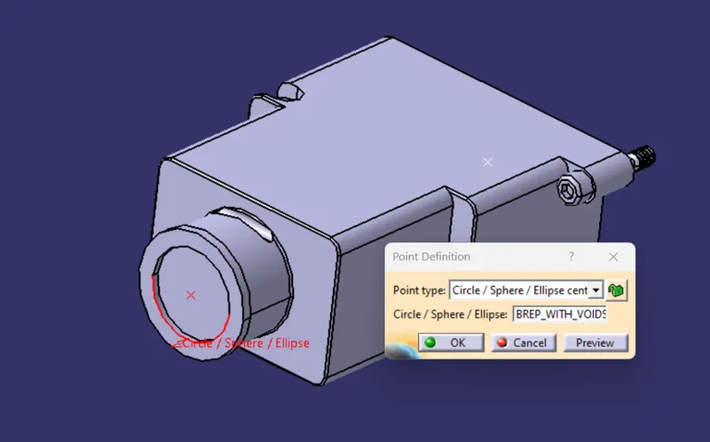
create another point as shown below by using circle/sphere/ellipse centre selection type
AXIS SYSTEM CREATION
before we create Axis System we should known the entry and bundle connection side and connector side
for more information we can ref the drawing which is provided.
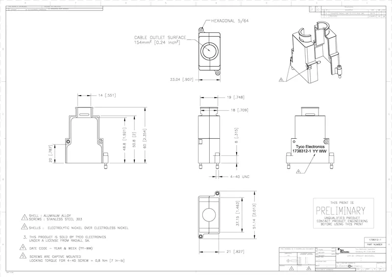
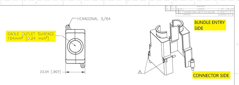
in this case we consider rectangular side is connector connection and circular side is bundle connection side..
AXIS SYSTEM
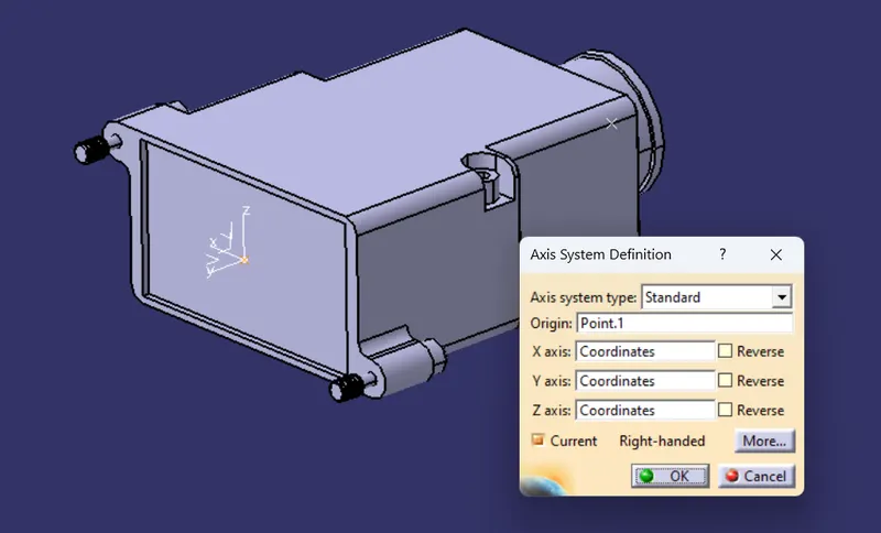
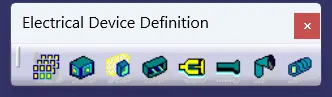
Define Part as Electrical component (Back shell)
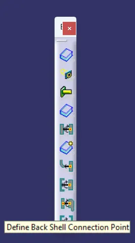
click on the icon showing back shell

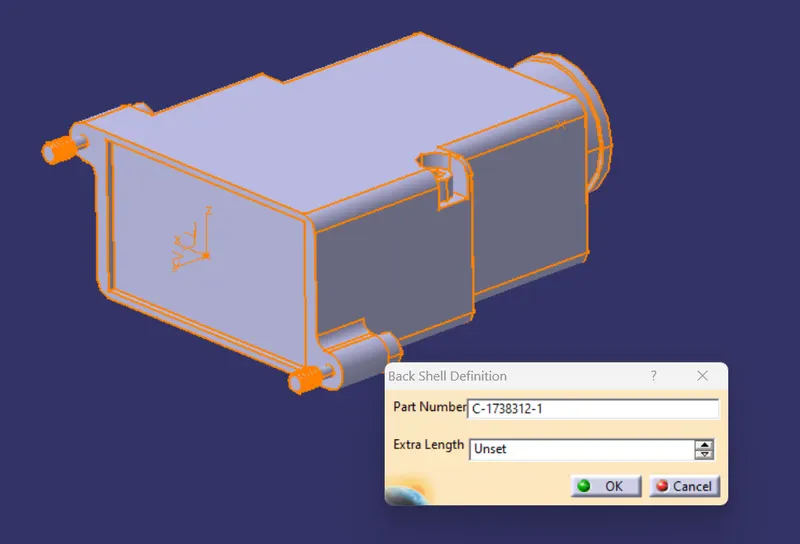
After creating the part as backshell
we have to Define the Backshell Connection point
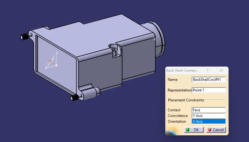
Define Bundle Connection Point
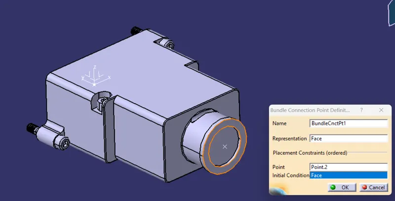
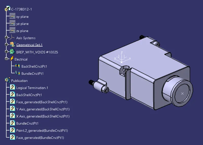
Electrical properties are created
CORRUGATED TUBES
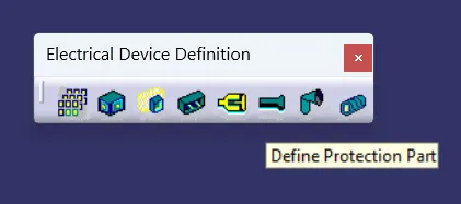
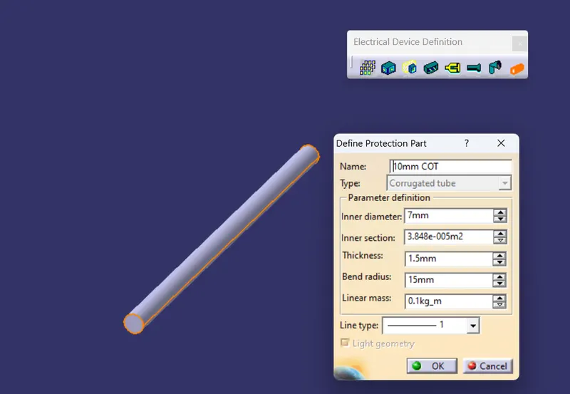
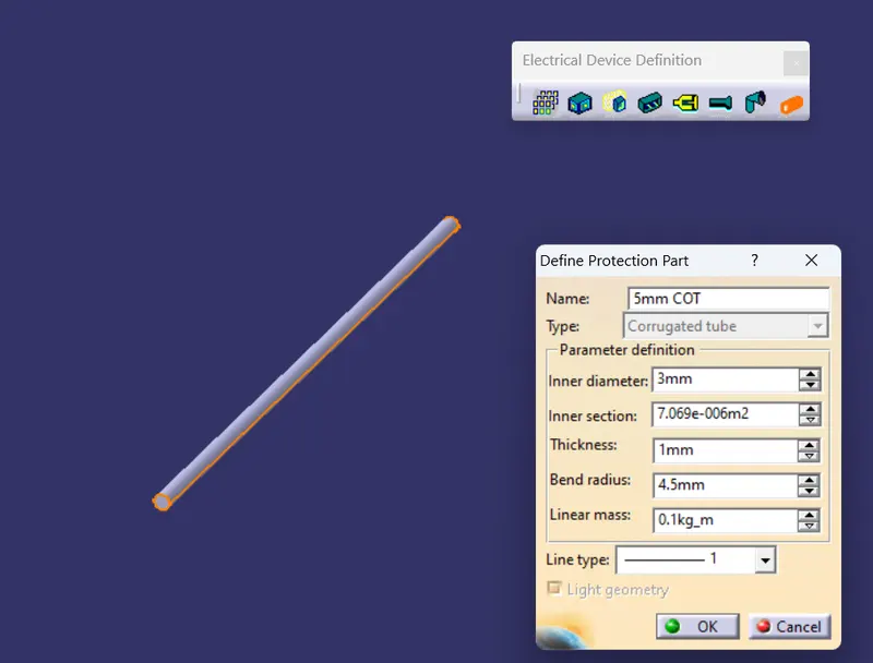
Select the command Define Protection Part
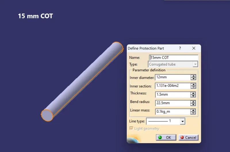
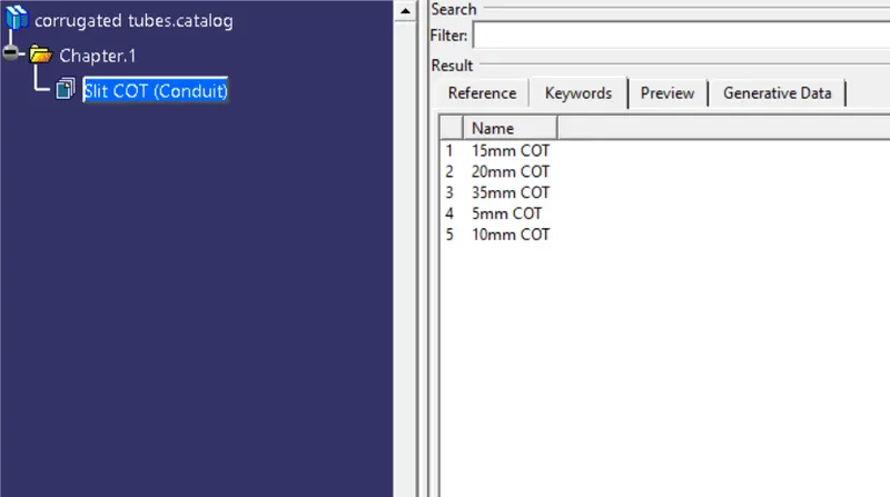
15mm COT
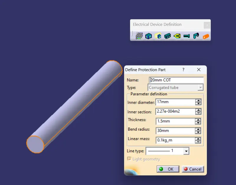
20mm COT
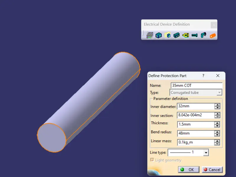
35mm COT
10mm COT
5mm COT
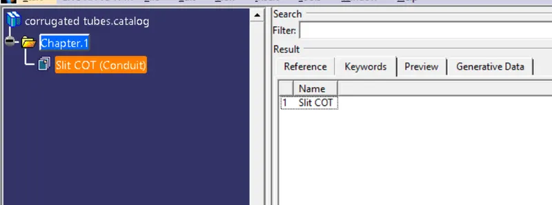
CATALOG IS CREATED and stored as shown below
Conclusion
P clamp is downloded and support properties are added
Back shell properties are added and electrical properties are defined
Corrugated Protective tubes are created and are added to the catalogue.