Week 8 - Challenge 4 - Bumper
Challenge 4 - Bumper
Aim: To Create Bumper Using Class A Surface.
CLASS A SURFACE
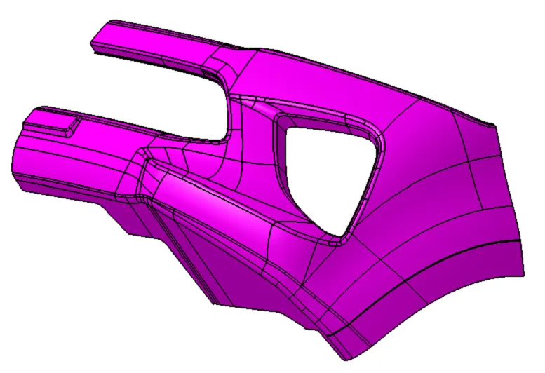
Class A surface is the outer most surface of the component, it is an aesthetic surface. It is also called as Strak. As a designer we don't have rights to modify the class A surface without permission.
Then we have check the class A surface whether it is joined or not by using boundry command if the boundry command shows only the the outer edges means we can work on class b otherwise we have to correct class A then only we can work on Class B.The above image is the Class A Surface. We can give different colors to identify the separate surfaces.
TOOLING AXIS
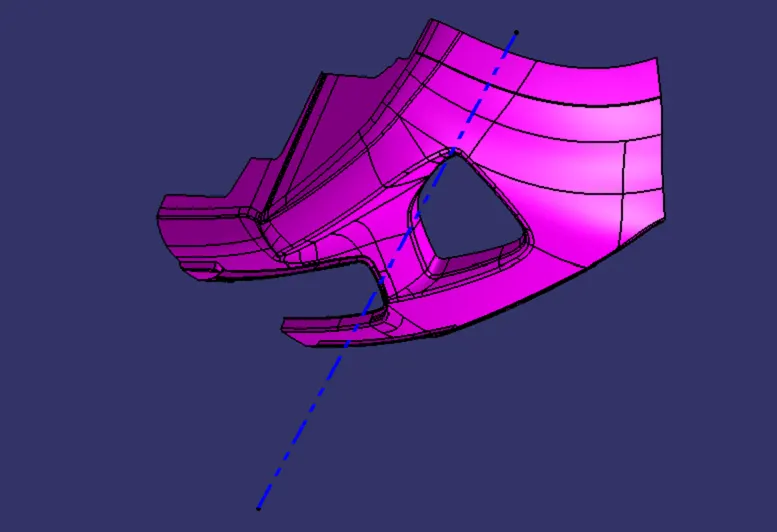
Tooling axis is very important to design a product. It is nothing but the direction of the molds open close and whether it is moves in the x, y or z direction. First we have to decide which direction is probabily suitable for the particular product. Once we get the Cass A Surface, we can check the surface and able to create the tooling direction.
Procedure to Create the Tooling Axis:
- First we have to create a point on the flate face or circle midpoint to create a line.
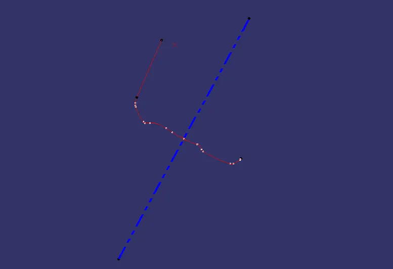
- Once we created the point means we can create a line (Dummy axis) on the point in the suitable direction. We can find the suitable direction by simply see the object from x,y and z directions. If the object is fully visible from one of the direction means that is the line direction.
- After finding the direction just create a dummy axis and axis system.
- Then intersect the part with yz plane and create an bisecting line using the side angular lines which might create a problem.Do the same step in the xy plane to create an another line.
- After creating the two line which might create a problem, then draw a biseting line using the two bisecting line that we drawn from the yz and xy plane.
- In this Bumper we can select any point in the x direction becasue from x direction only we can able to see the hole structure. Here we can also use other tooling axis creation method by using the center of gravity point.
Draft Analysis:
Draft: Draft is used to remove the component fom the core and cavity. It will reduce the wear in component and molds so the the life of core and cavity will increase.
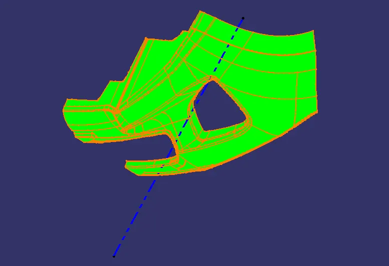
Draft Analysis: The Draft Analysis allows the user to easily analyze a part for proper draft angle. A Draft Angle describes the amount of taper for molded or cast parts perpendicular to the parting line.
The minimum draft angle ranges between 0.5 o 3 degree. Mostly 3 degree angle is widly used to make many components.
Draft: Draft is used to remove the component fom the core and cavity. It will reduce the wear in component and molds so the the life of core and cavity will increase.
Draft Analysis: The Draft Analysis allows the user to easily analyze a part for proper draft angle. A Draft Angle describes the amount of taper for molded or cast parts perpendicular to the parting line.
The minimum draft angle ranges between 0.5 o 3 degree. Mostly 3 degree angle is widly used to make many components.
DRAFT ANALYSIS FOR CLASS A SURFACE
CLASS B SURFACE
OFFSET
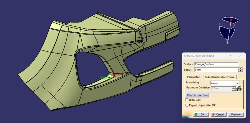
First we have to Offset the class A Surface to 3mm
after Offset look for the surface and we have to modify the surface where ever the surface is broke while offset.
BROKEN SURFACES
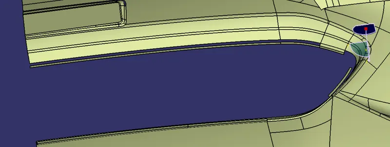
REPAIRING THE SURFACE
we have to extract the surfaces that are broken from the class A Surface and Offset them to 3mm and later we have to do extraplote and trim when evere there is a need for it.
below fig shows the broken surface
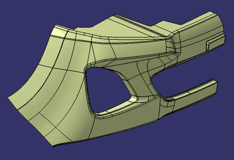
FINAL CLASS B SURFACE
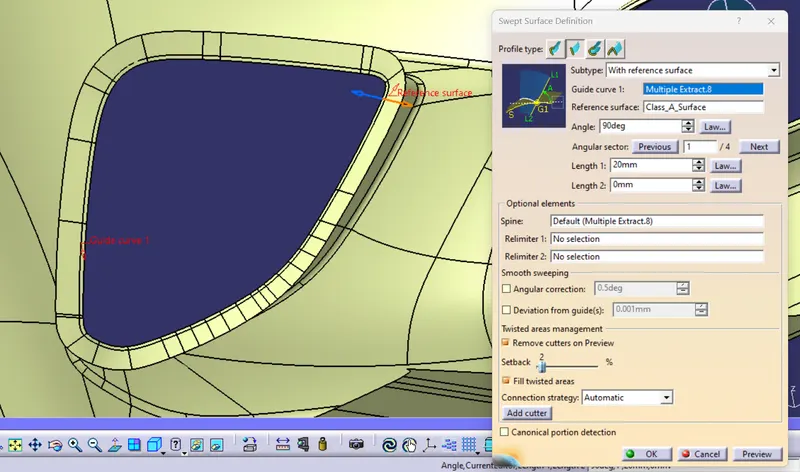
CLASS C SURFACE
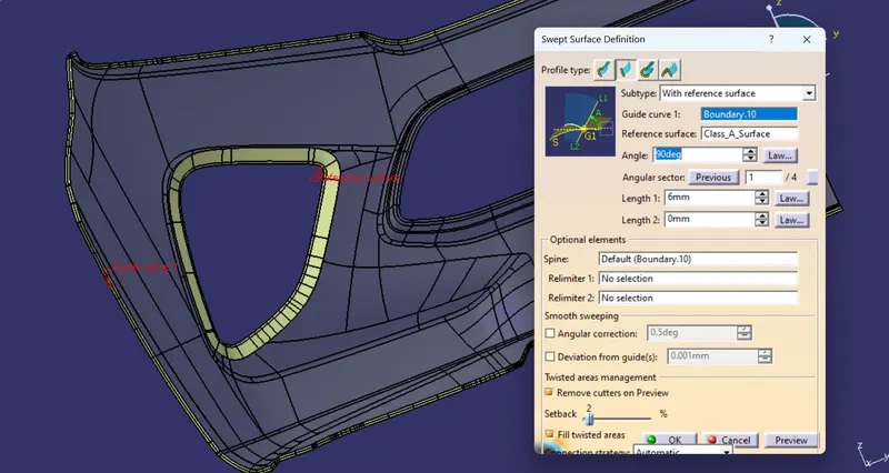
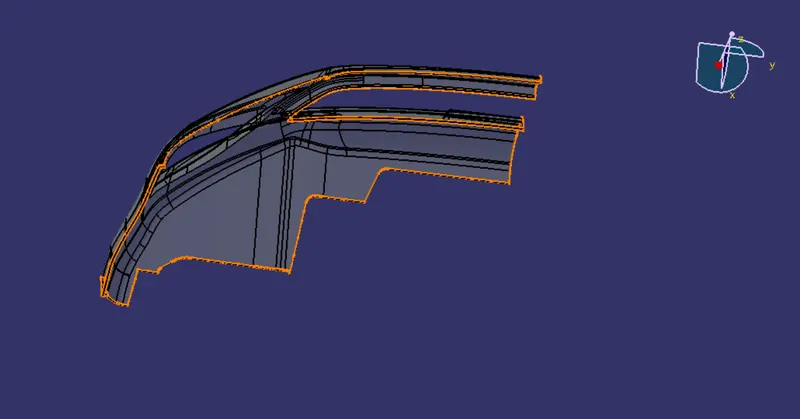
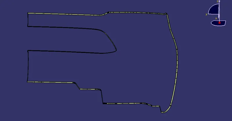
CLOSED SURFACE
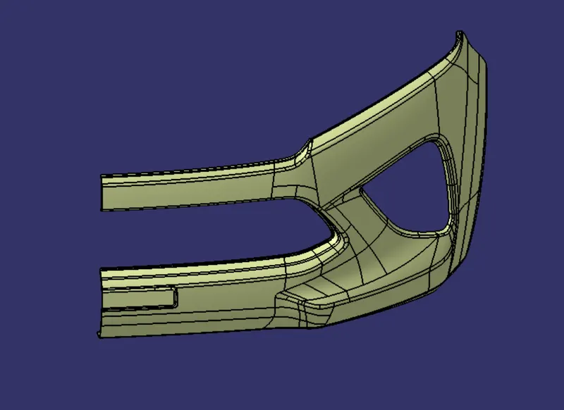
PART BODY
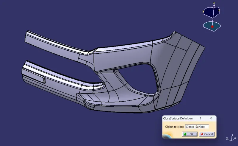
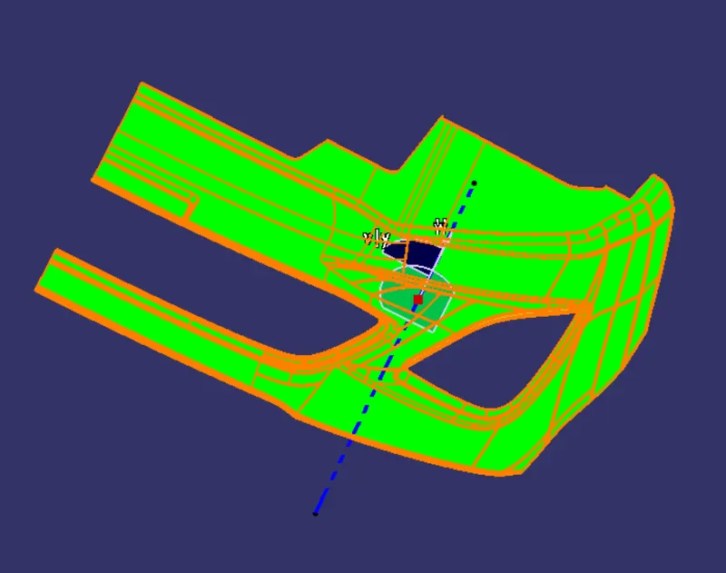
DRAFT ANALYSIS FOR PART BODY
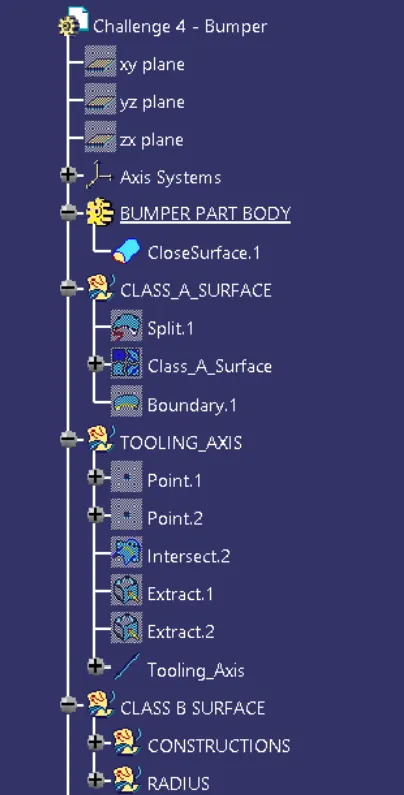
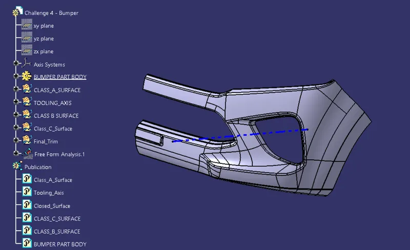
TREE STRUCTURE
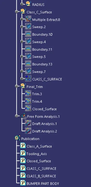
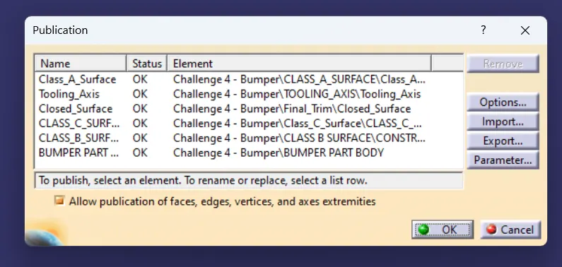
PUBLICATIONS
CONCLUSION
Bumper is created by using Class A Surface