Roof Design
Aim:
The main aim is to determine the heat distortion criteria,snow load criteria and draft analysis.
Roof:
An automobile roof or car top is the portion of an automobile that sits above the passenger compartment, protecting the vehicle occupants from sun,wind,rain and other external elements.
Safety point of view vehicle roof plays a very crusial role especially in rollover kind of accidents vehicles rollover crashes are the cause for several head,neck and spine injurie for this reason stiffness and strength af any vehicle is crucial, in order to achive this embosses with reinforcement are provided on the surface of the roof.
Heat Distortion Criteria:
During summer in the middle east, the heat radiating from the sun causes the roof car to change in metallic regons. Heat distortion criteria indicate what temperature materials start to "soften" whem exposed to a fixed load at elevated temperatures.
`W=[1.73*10^(-3)*L]+[1.85*10^(-8)(R^2/t)]+[1.10*10^(-3)*l]-2.68`
Where,
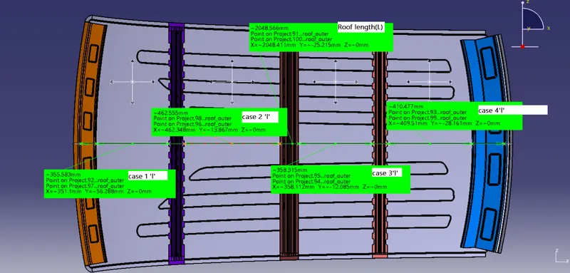
L= Roof length in X-Direction(mm)[Roof Dimension with OY]
R=Roof curvature=`2(Rx*Ry)/Rx+Ry`
Where,Rx=X Curvature and Ry=Y curvature
t= Roof plae thickness(mm)
l=Bow roof thickness(mm)
Judgement condition
Ok<2.7
Snow Load Criteria:
During winter season the snow gets clogged over the top areas of the car and the snow has some mass on it.The roof can fail if the snow load exceeds the capacity of the was designed to sustain.
`Qr=[ly*t^2]/[alpha*S ][Rx+Ry/2]^2*10^8`
Where,
`alpha=My*L^2*10^-12`
where,
`alpha=My*L^2*10^-2`
t=Roof plae thickness(mm)
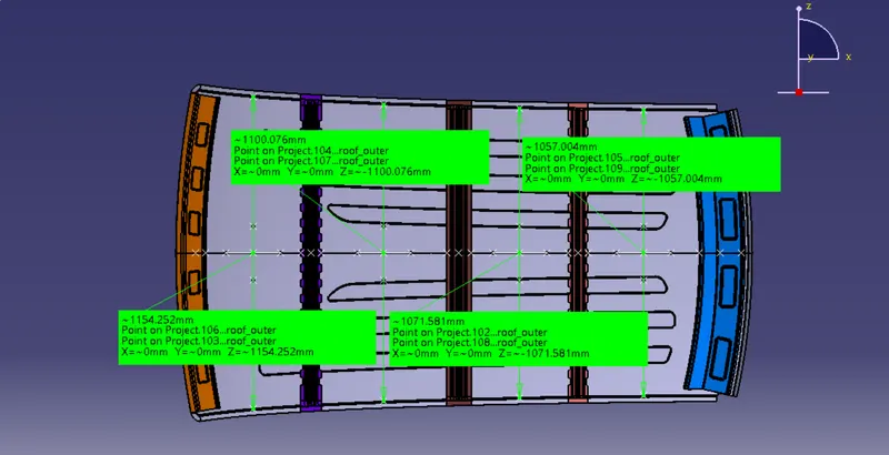
Lx=Distance between the left and right end of the roof on the roof bow(mm).
(width of the roof panel exposed on the surface)
Ly= Distance between the front and rear roof rails on the vehicle along with OY(mm) (Length of roof rail front / Rear as the refer point of the front and the rear.)
y=Distance from front roof rails to roof bow(mm)
s=Distance for which roof bow bears divided load(mm)=L12+L22
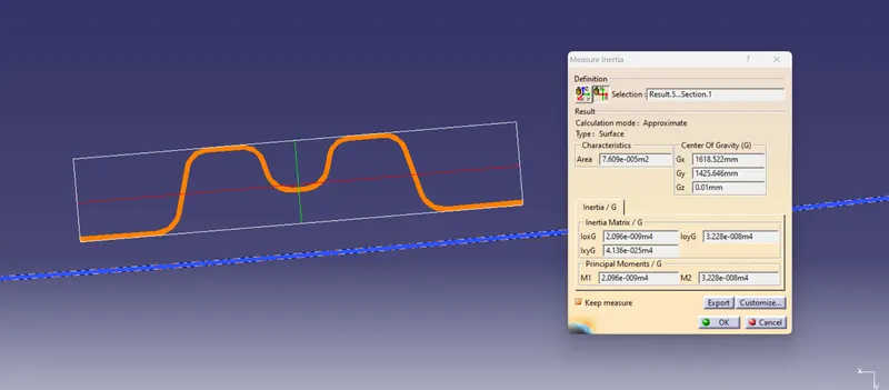
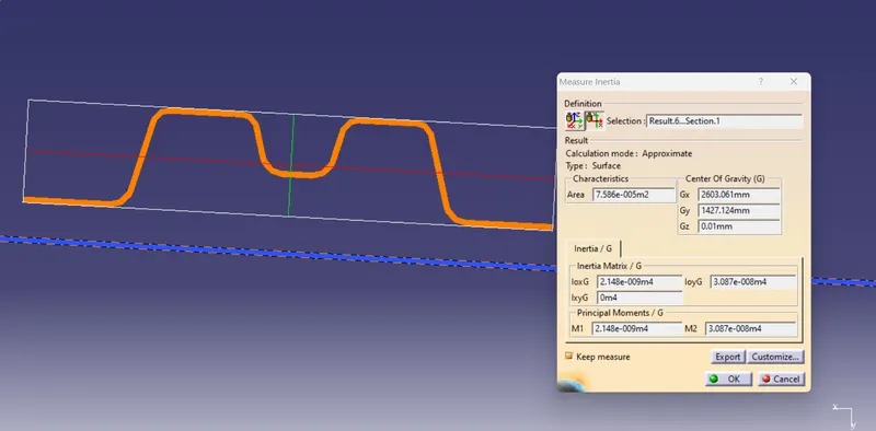
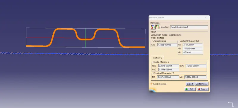
ly= Geometric moment of inertia of roof bow(`mm^4`)(Y cross-section)
Rx=Lateral direction curvature radius of roof panel Y cross-section on roof bow(mm) (roof panel curvature radius of the length Lx in front view)
Ry= Longitudinal direction curvature radius of the roof panel X cross-section on roof bow(mm)(Roof panel x curvature radius of the length 'S' in side view)
Procedure:
1.Checking the class A surface:
- After the file is opened the roof part is not joined together but as the individual surfaces.
-
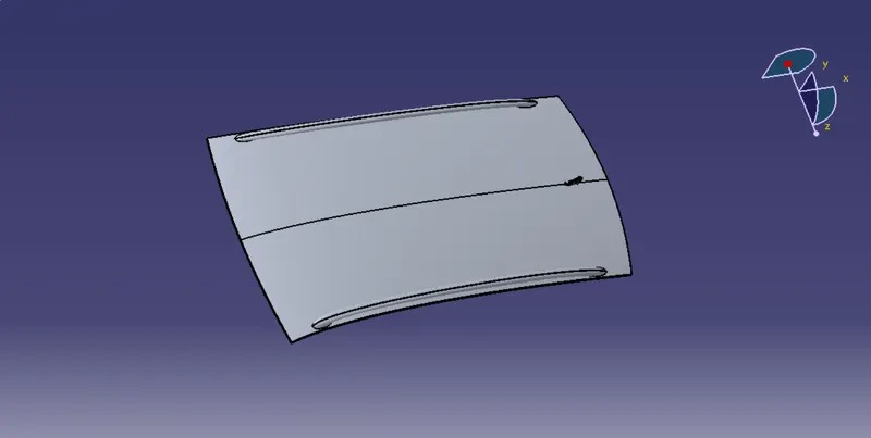
- It is also seen as the surface is perfectly symmentrical in shape which helps us to work on the half of the portion and reflect it which creates the whole roof.
2.Creating the Flange for the roof:
- Extract the upper roof by selecting it.
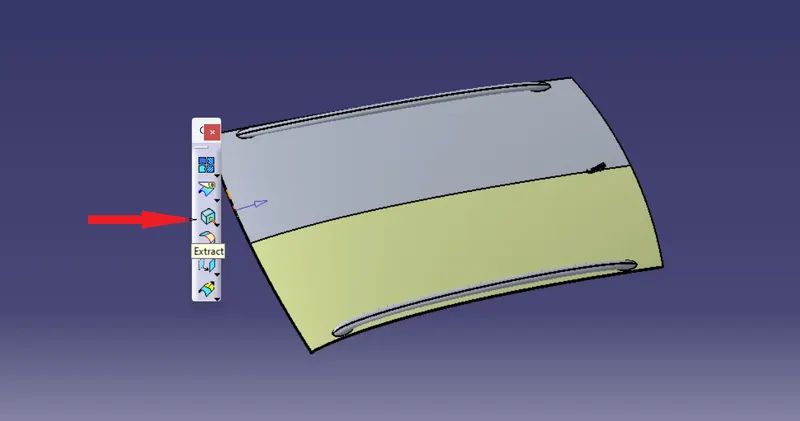
- after extracting it hide the class A surface and modifiy.
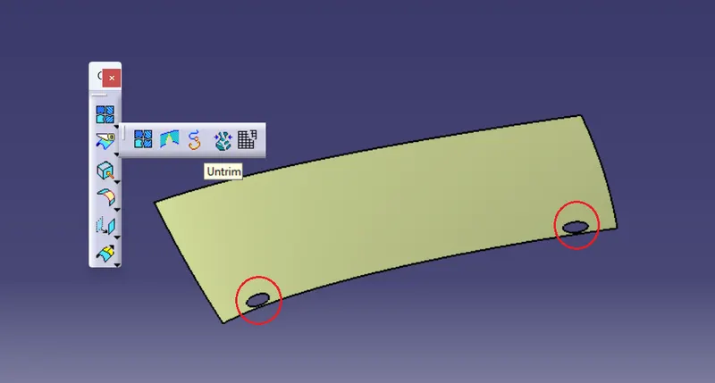
- after extracting the suface we see that there is a cuts in them, so to repair use untrim and modify the extracted.
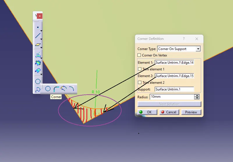
- Now,since it is a shape corner at the end to make it smooth,use the corner option to create a cut on the edges and split it to create the smooth corner.
- Now select an edge and sweep it with the 15deg draft with a length of 15mm.
- From the edge of the sweep take another sweep with the 25deg draft of kength 21.5mm(as shown in the referance dimensions).
- Follow the same procedure with the other edges.
- Now,create the curved edges by using curves as the guide curves as the guide curves and multi-section surface option.
- Join the surface togrther and give the fillets.
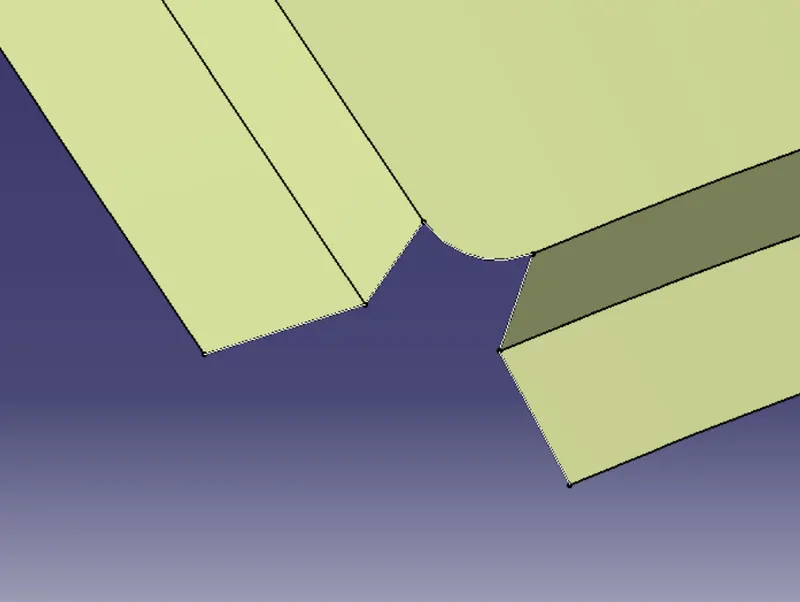
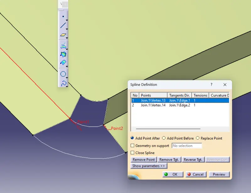
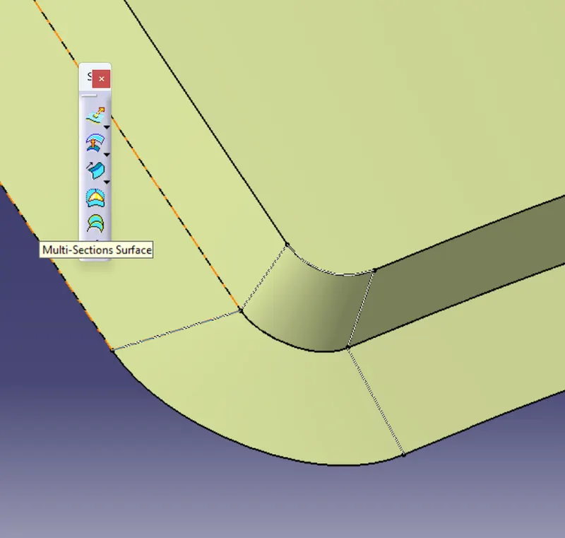
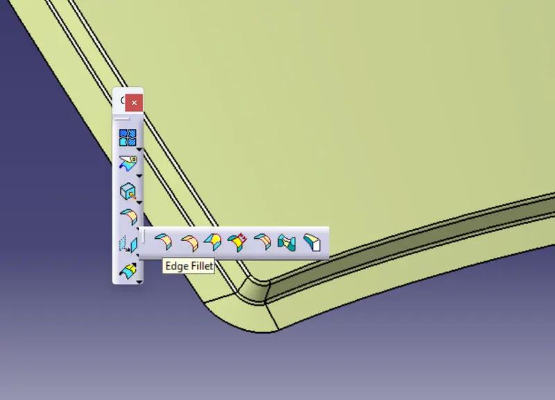
after creating the as the master section create edge fillets as shown in above figure.
- For the rear end there should be an additional area that helps to hold the back door without hitting the roof.
EMBOSES ON ROOF TOP
Frist shep in ctrating emboses is extract the roop top surface and give offset of 5mm for creating emboses.
The steps followed to create emboses are mentioned below..
For creating the embosses on top we have create the profile and project to surface so it will create the same as in roof now by using the smooth curve somoothing opertion is done and after that we have to split so the unwanted surface will be deleted.
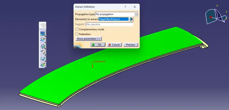
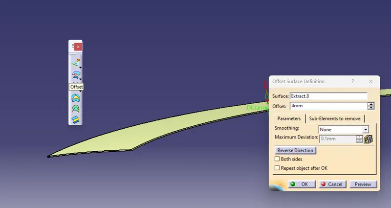
after offset hide the extracted surface and unhide the roof top because we need to cut the roof top to perform the sweep operations.
- Sketching:-
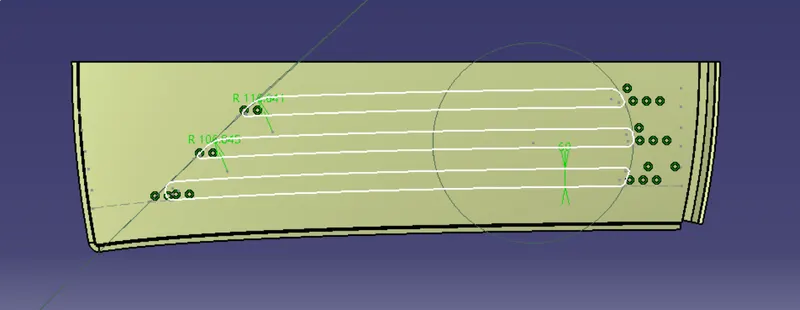
- Projecting and Split:-
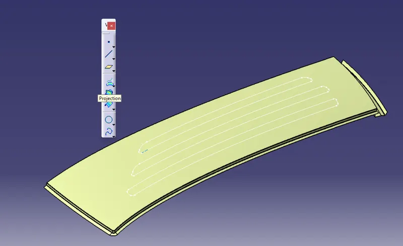
after the sketching we have to project the sketch to the roof top where we need to perform or create the embosses

now using the split we have to cut unwanted surface as shown in the figure.
- Sweep,Trim and Edges:-
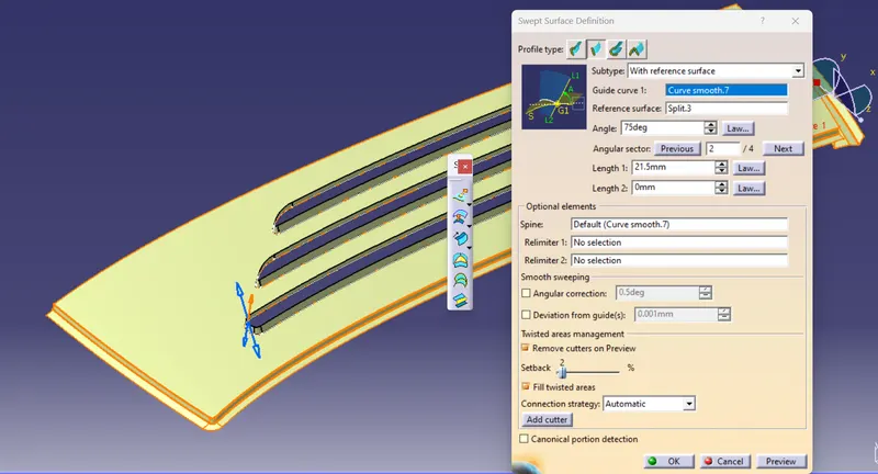
now using sweep give a clear look to the emboses to select the guide curve and give angle
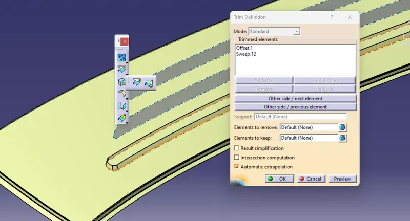
after that by using trim command cut unwanted surfaces. and follow the same procedure for next 2 emboses and apply edges.
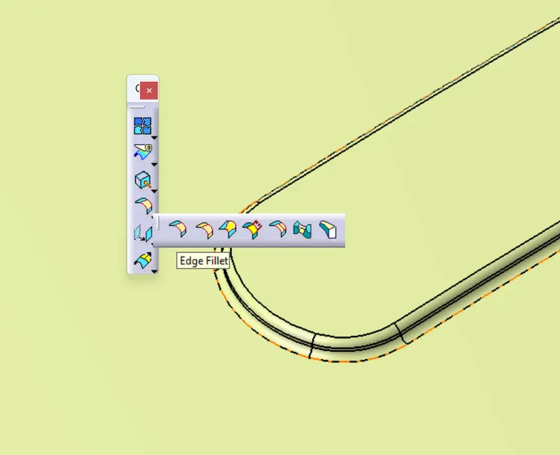
- Boundary--->Curve Smooth---->Extrapolate--->Split--->Symmetry--->Join
- Boundary:-
By using projection command create the projection as shown in the below figure.
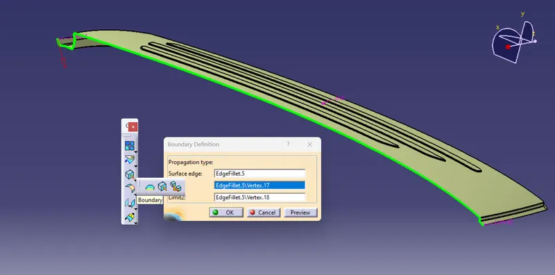
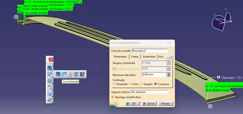
- Curve Smooth:-
Now by using Curve smooth smoothen the curve and give curvature continuity as shown in the figure.
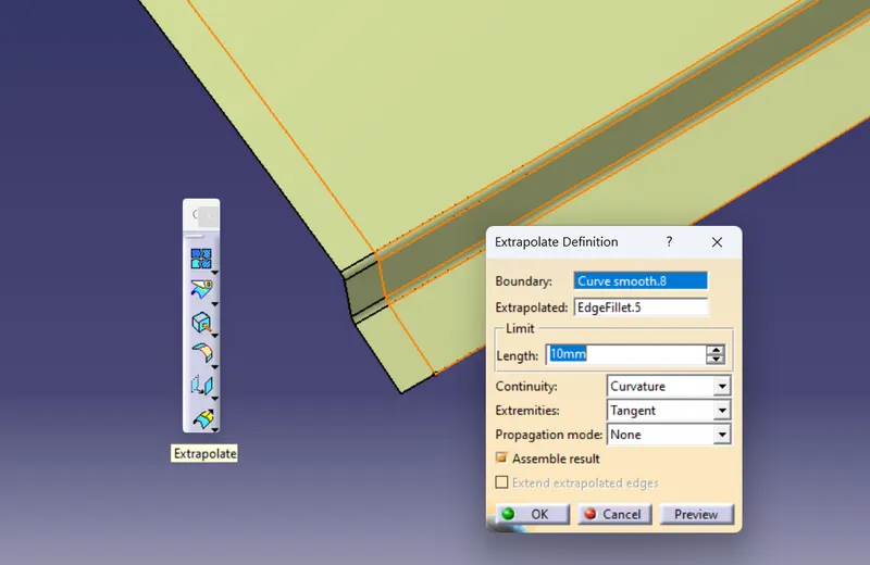
- Extrapolate:-
Create the extrapolate and select continuity as Curvature so that there will be no error while joining..
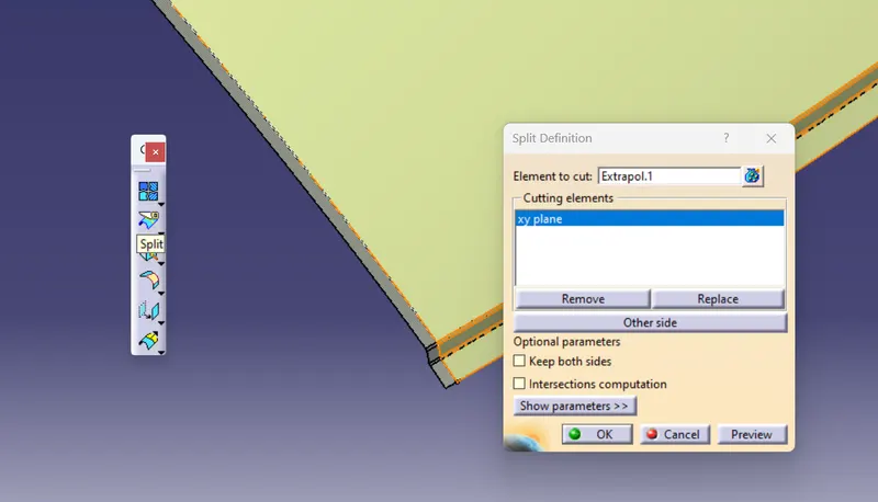
- Split:-
Now select the split and cutting plane as xy plane
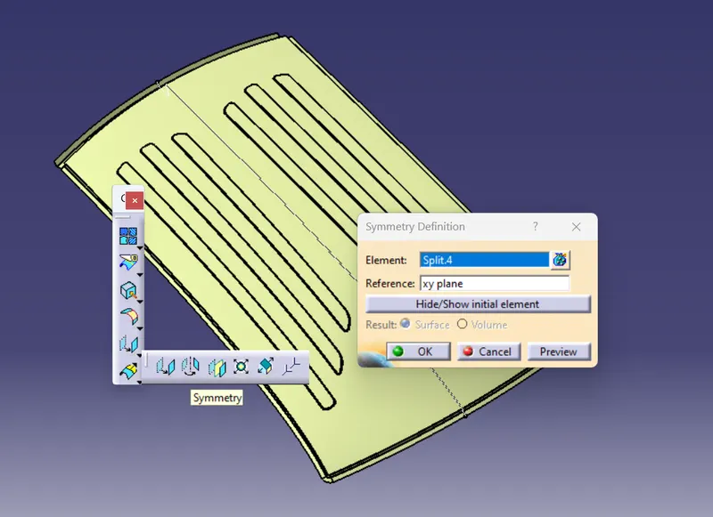
- Symmetry:-
- Join:-
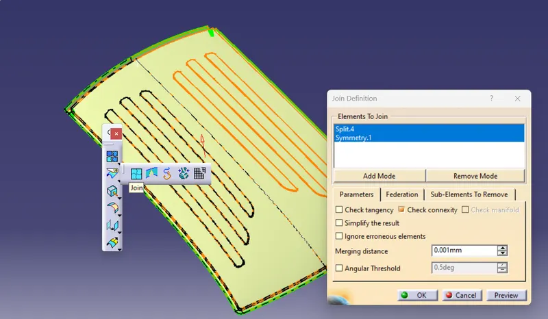
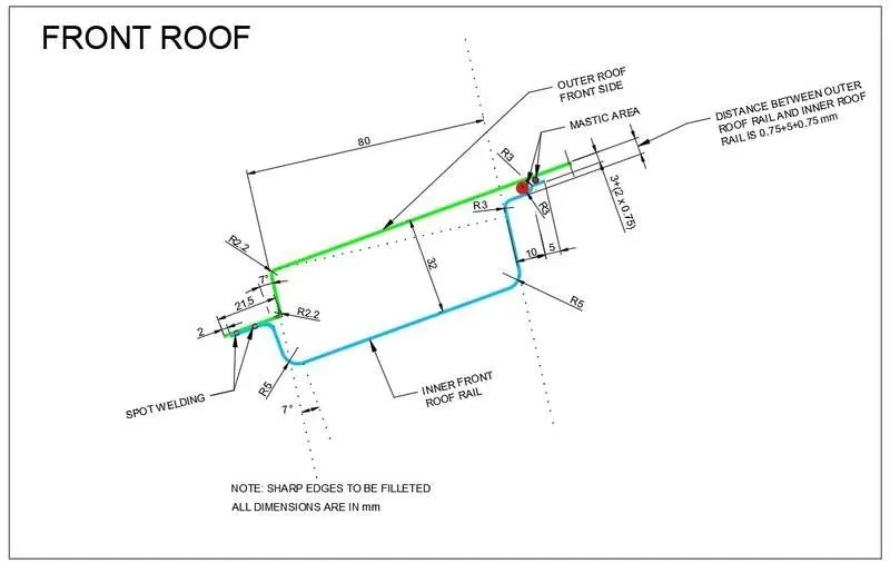
3.Creating the front roof rail:
The below master sedtion is given to create Front Roof so we need to follow this master section.
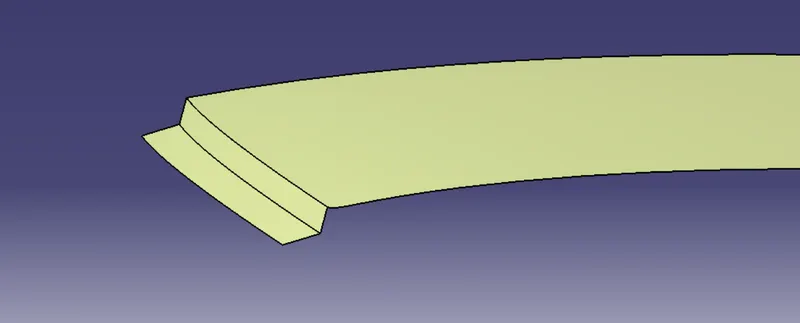
- Extract:-First extract these 3 surfaces from the roof.
- Offset:-
offset the above extracted surfaces as respect to the master section.
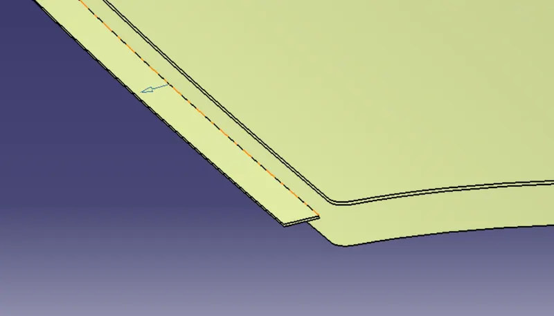
Now create the respective sweep for these offsets and trim them together.Give the edge fillet to it.
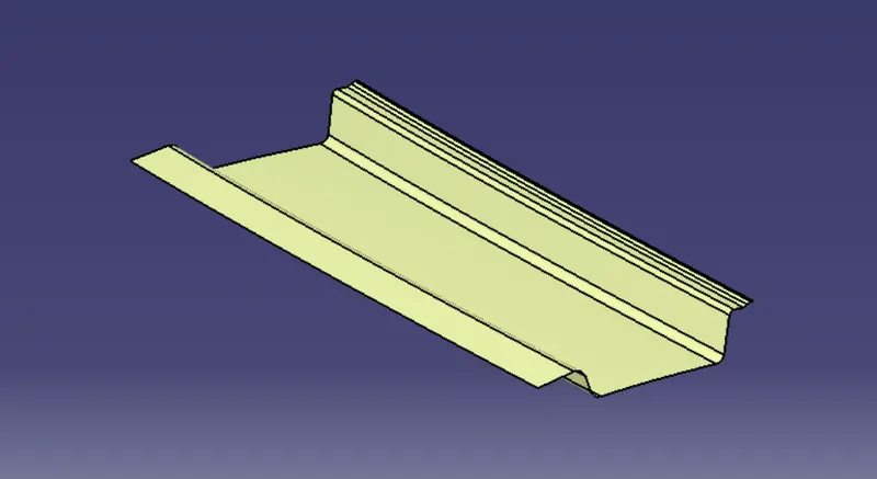
- Embosses
Embosses are created to give strength to the front roof rail, to create that we need to offset the extracted surface that is from roof body and create the skeching and by using split,trim and swwep operatons we can complete the procedure of embosses.
- Sketching:-
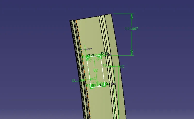
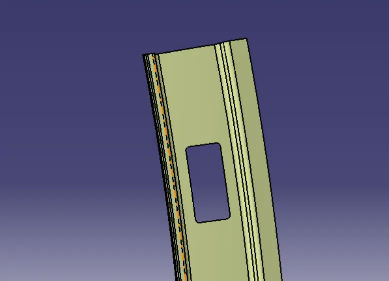
- Split:-
- Sweep:-
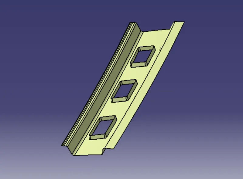
after creating the sweep we should apply edges and symmetry and join the both elements and give thickness to it.
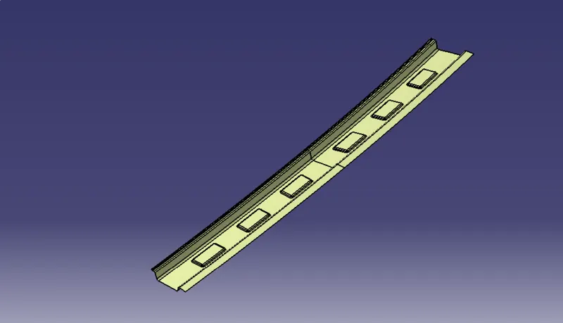
- Thickness
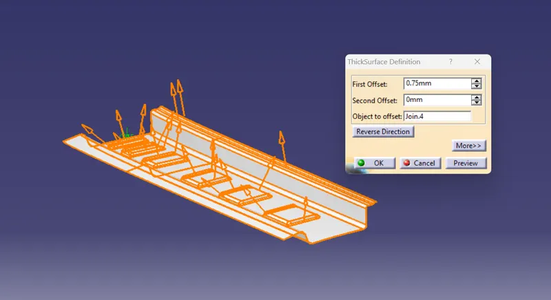
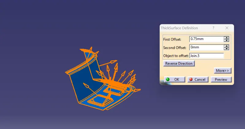
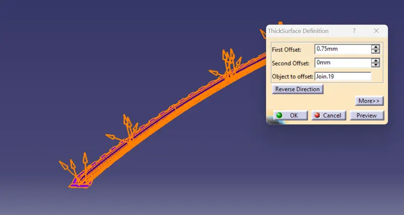
After completing the front roof rail we have to give thickness of 0.75mm as mentioned in master section.
4.Creating the rear roof rail:
- Master section:-
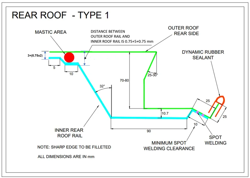
- Extract:- extract required surfaces with respect to master section.
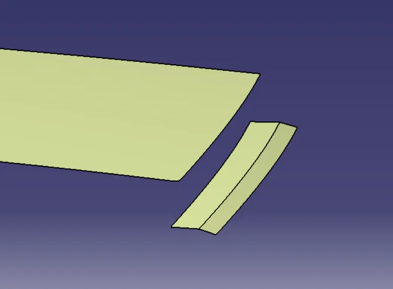
- Offset:-we need to offset with respect to master section for further procedure.
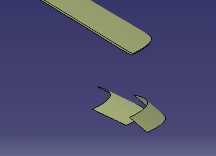
- Sweep:-For the rear roof,rail follows a similar procedure as the front roof and the values for it are given in the diagram.Make sure that the rear surface has a positive draft angle.
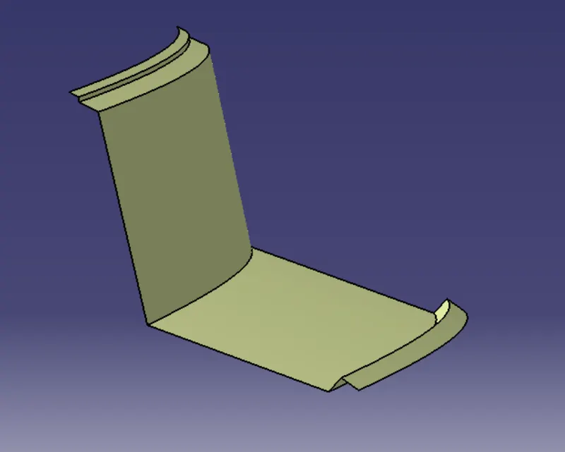
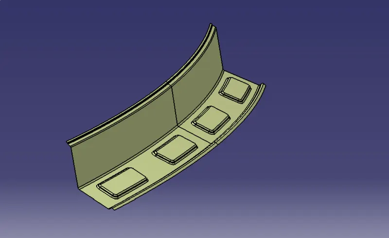
- Embosses:-Follow the same procedure as front roof rail and apply edges
- Thickness:-give thickness 0.75 mm
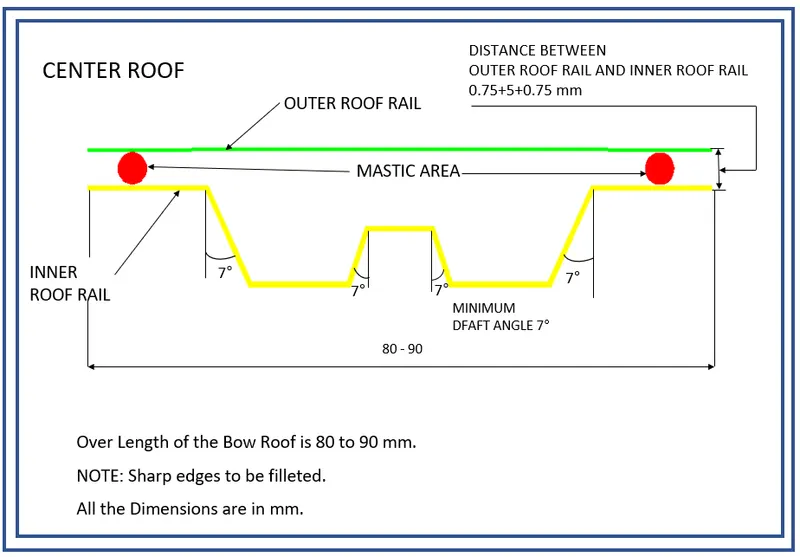
5.Creating center reinforcement :
- Master section
- Extract:-
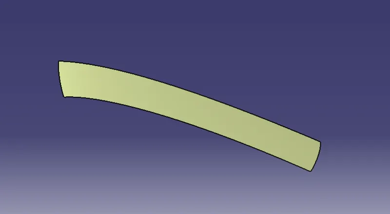
extract the roof outer surface as shown in figure.
- Offset:- offset the extracted as per required by the master section.
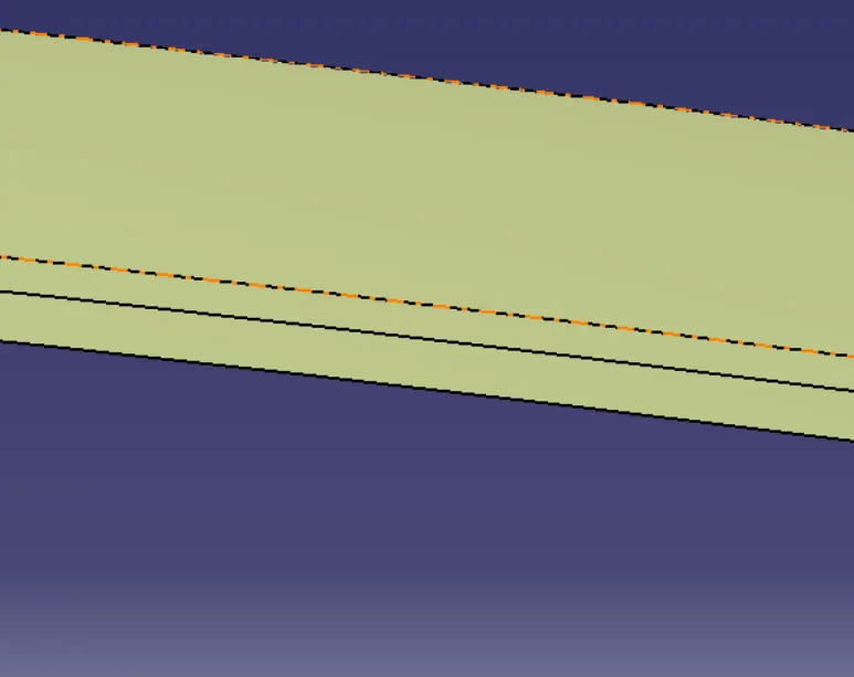
The center reinforcement is attached at the center yet below the roof.
To create the center reienforcement as per the diagram , we use the offset and select the parallel curve option and give an offset value of 50mm on both sides and create a cut on the offset.
Now create the part as per the design standards and make sure that the offset is given considering the thicknss of the component.
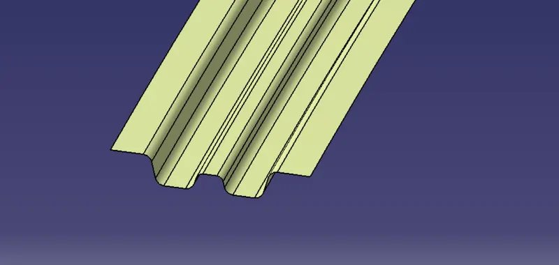
A dip area needs to be created so that reinforcement is attached to the roof flange.
To create that area, select the flange and create an offset to the length including the thickness of the roof and the connecting parts.
Cut the offset to the length which is less than the width of the centre reinforcement.
Create lines on the surface.
Use connect option t join the lines to forms curves.
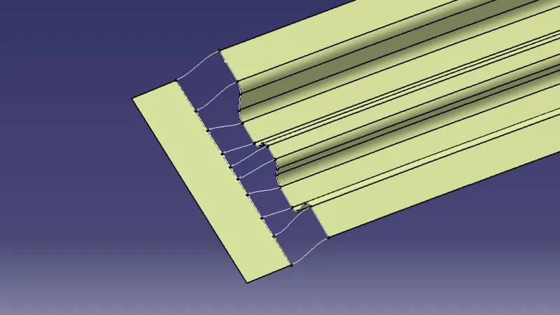
- Multi-section surface :-option to select the edges and the curves crated as the guide curves to create a body.
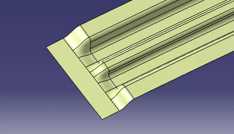
- Join:-
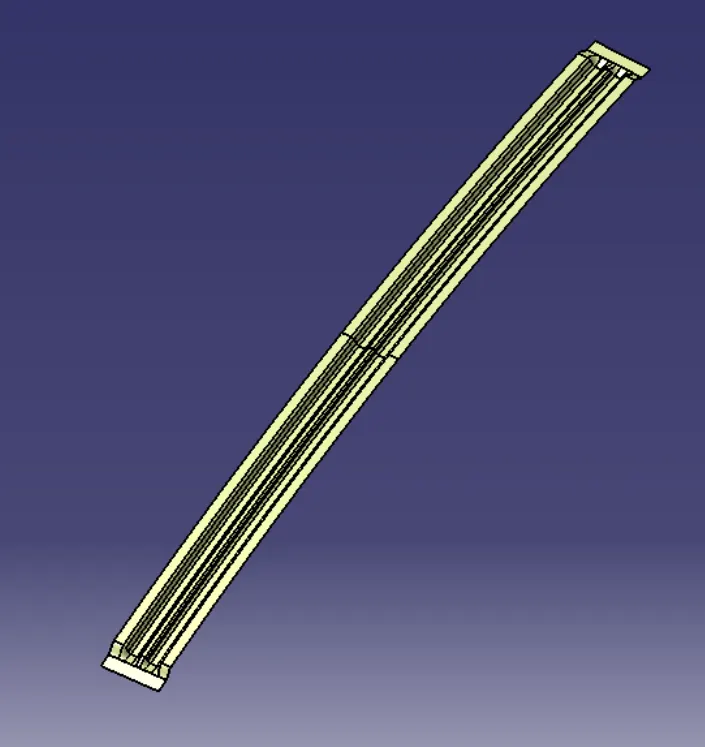
- Thickness:-
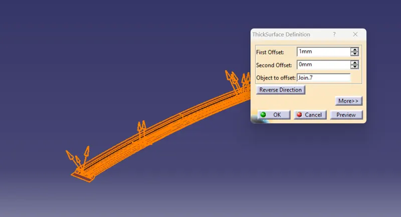
6.Creating the Bow roofs:
- Master section
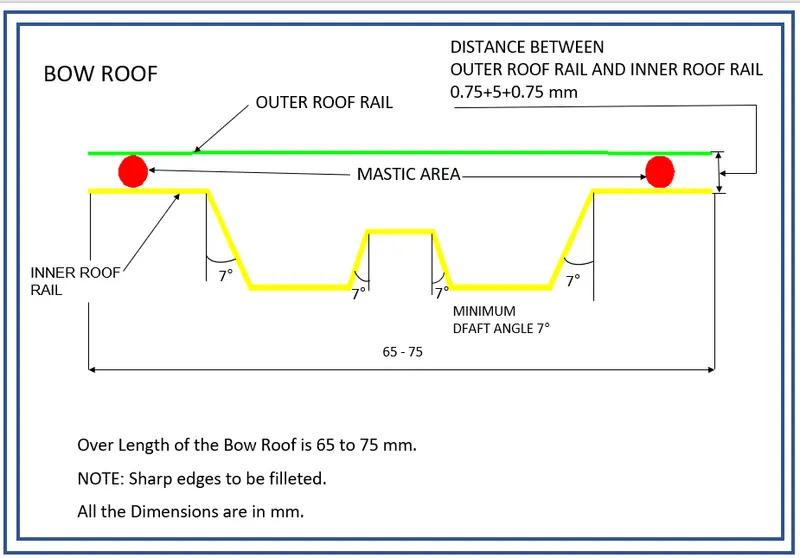
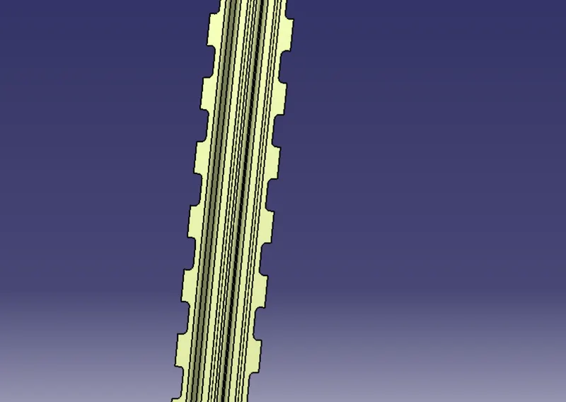
2 bow rofs are created to give the strength to the roof.Follow the same method as with respect to center reinforcement to create the bow roof.Now, after the bow roof is created. the mastic points need to be created.Use the parallel curve and connect the outer edge and parallel curve to cut the elements.
- Cutouts for Mastic Points:-
- Thickness:-
7.Checking the Heat Distortion Criteria :
To calculate the heat distortion criteria, we have to take note of few values and note it down.
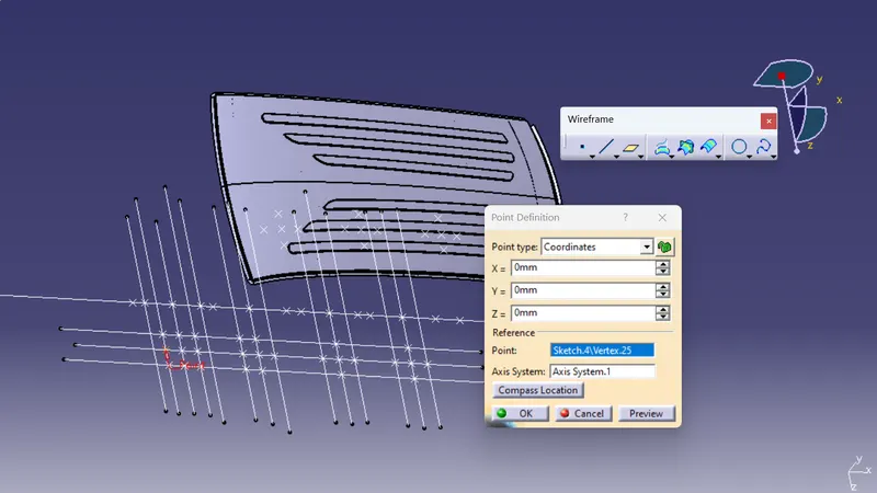
to note down, first we need to create a sketch.
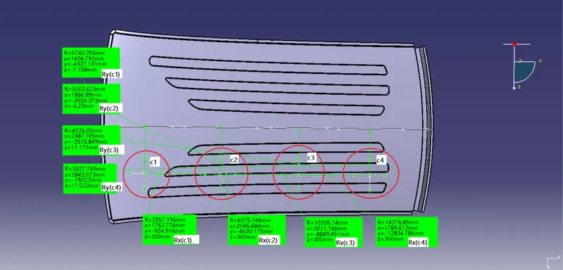
Create a line at the center of roof part in the roof part in the 0-Y axis and then draw another line with the distance of 300mm
Now create the line between the rails in the X-direction and create 2 lines with a distance of 100mm on both sides.
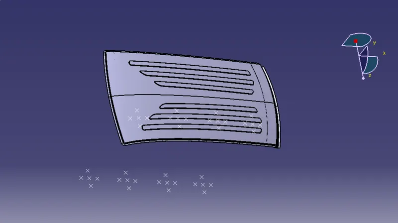
Now cretate a point coinciding with both the lines.
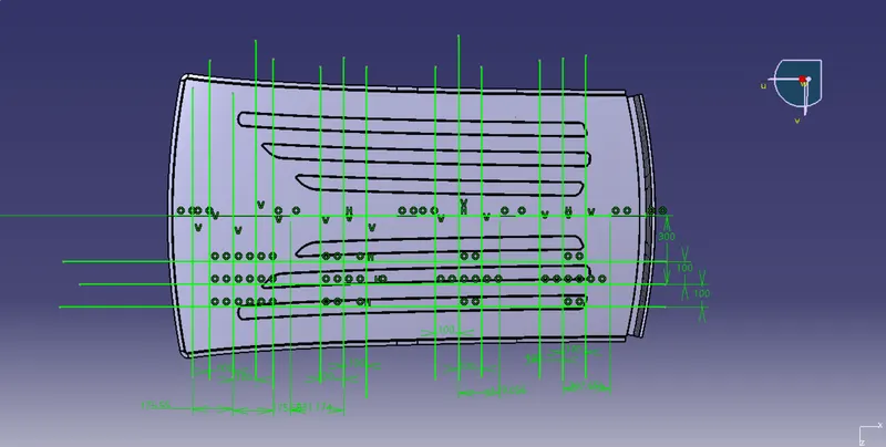
Extract the points to the roof and create the arc using 3 points by creating two lines intersecting with each other.
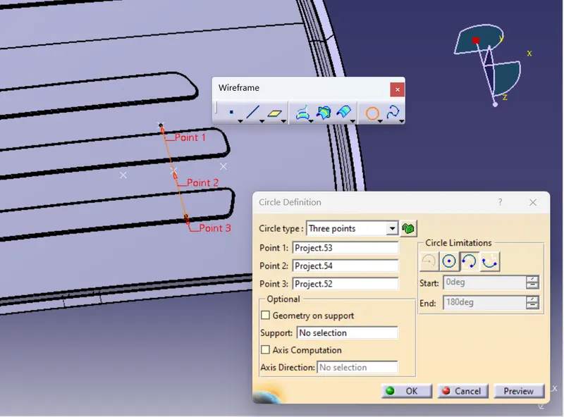
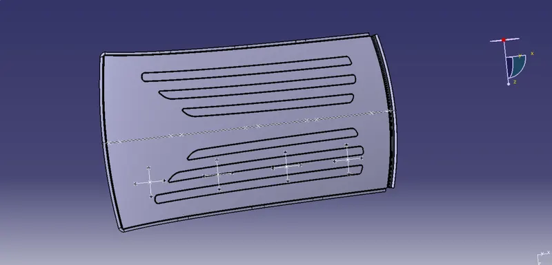
Measure the radius of the arc in the Y direction as Ry and x direction as Rx
- Cases:-
8.Checking the snow load criteria:
To calculate the snow load criteria, we have to take note of few values and note it down.
To note to take of few values and note it down.
To note down,firet we need to create a sketch.Create a line at the center of the roof part in the 0-Y axis.
Now create the line with a distance of 100mm on both sides
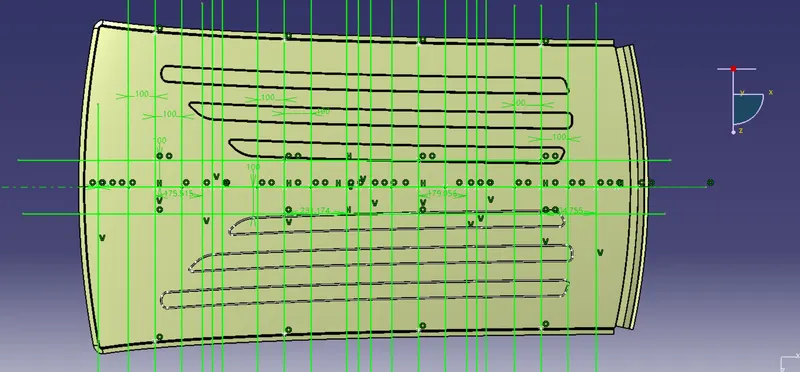
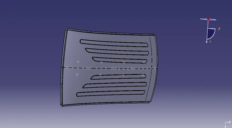
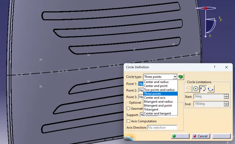
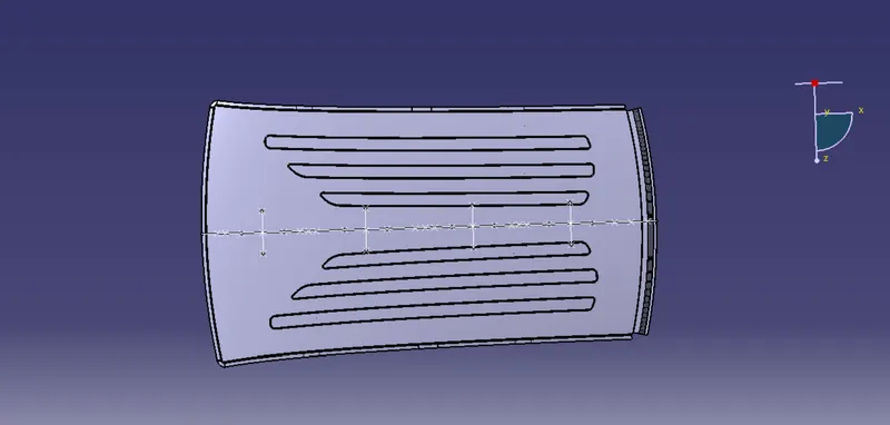
create the lines between the rails in the X direction and create 2 lines with a distance of 100mm on both sides
Now create a point coinciding with both the lines.
Extract the points to the roof and crate the arc using 3 points bt creating two lines interseting with each other..
Measure the radius of the arc in the Y direction as Ry and X direction as Rx.
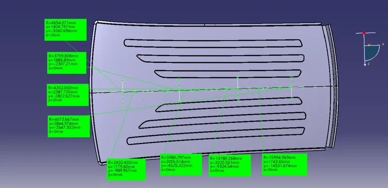
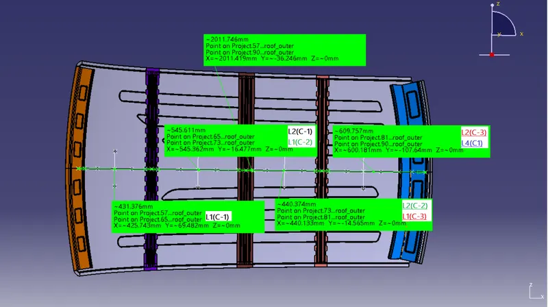
Lx value
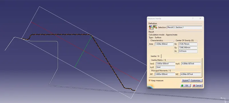
Moment of inertia:
Boow roof 1:-
Boow roof 2:-
Center roof:-
Rear Roof:-
RESULT
Calculation:
Heat Distortion Criteria:
`W=[1.73*10^(-3)*L]+[1.85*10^(-8)(R^2/t)]+[1.10*10^(-3)*l]-2.68`
| Cases | Roof length 'L' in mm | Rx (X curvature) | Ry (Y curvature) | R'Roof curvature | Roof thickness 't' | Boow Roof span'l' | Heat distortion | Judgment ConditionResult |
| 1(front_roof-Boow_roof_1) | 2048.57 | 2357.2 | 5740.29 | 3342.02 | 0.75 | 355.583 | 1.53067 |
OK |
| 2(Boow_roof_1-Centre_roof) | 2048.57 | 6075.15 | 5002.62 | 5486.96 | 0.75 | 462.55 | 2.11546 | OK |
| 3(Centre_roof)-Boow_roof_2) | 2048.57 | 10335.1 | 4026.05 | 5794.76 | 0.75 | 358.315 | 2.08645 | OK |
| 4(Boow_roof_2-Rear_roof) | 2048.57 | 14276.9 | 3327.77 | 5397.46 | 0.75 | 410.477 | 2.03415 | OK |
Snow Load Criteria:
Qr = [Iy x t2] / [α x s x [(Rx + Ry)/2]2 x 10-8]
| Cases | Thickness | Ly | Lx | Y | ly | Rx | Ry | L1 | L2 | S | Alpha | My | Snow load criteria | |
| 1(front_roof-Boow_roof_1) | 0.75 | 2011.746 | 1154.252 | 431.376 | 2060 | 2432.432 | 4654.171 | 431.376 | 545.611 | 488.4935 | 0.908272 | 681733.7 | 20.80169 | PASS |
| 2(Boow_roof_1-Centre_roof) | 0.75 | 2011.746 | 1100.076 | 974.902 | 2148 | 5980.297 | 3759.808 | 545.611 | 440.374 | 492.9925 | 1.223263 | 1010821 | 8.447524 | PASS |
| 3(Centre_roof)-Boow_roof_2) | 0.75 | 2011.746 | 1071.781 | 1413.043 | 3357 | 10780.27 | 4252.002 | 440.374 | 609.757 | 525.0655 | 0.971805 | 845993.1 | 6.55077 | PASS |
| 4(Boow_roof_2-Rear_roof) | 0.75 | 2011.746 | 1057.004 | 2011.746 | 36650 | 15994.97 | 4072.667 | 609.757 | 2011.746 | 1310.752 | 0 | 0 | #DIV/0! | |
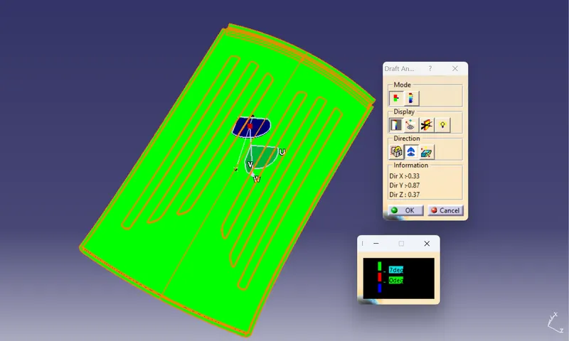
DRAFT ANALYSIS:-
Roof Top:-
Front Roof:-
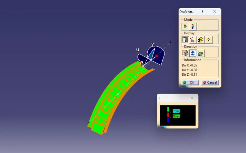
Boow Roof 01:-
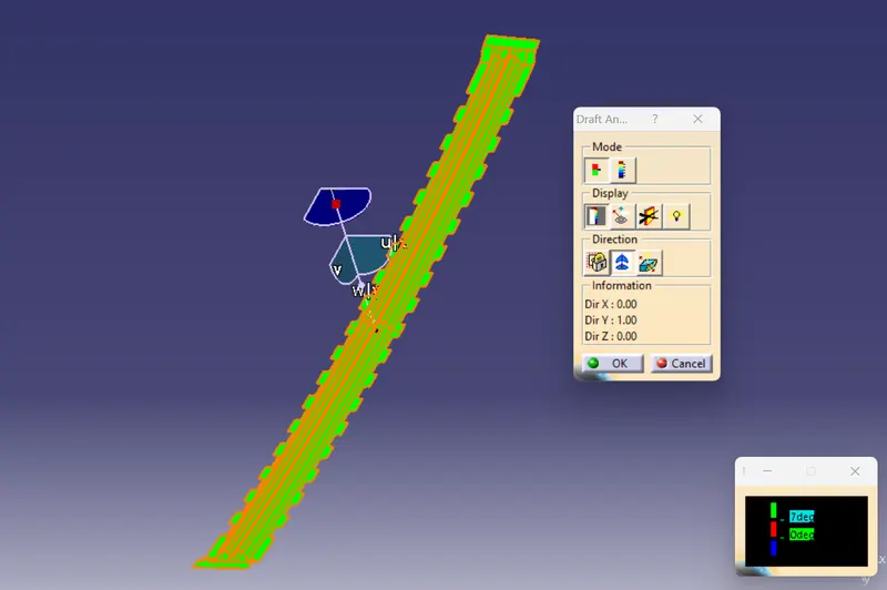
Center Roof:-
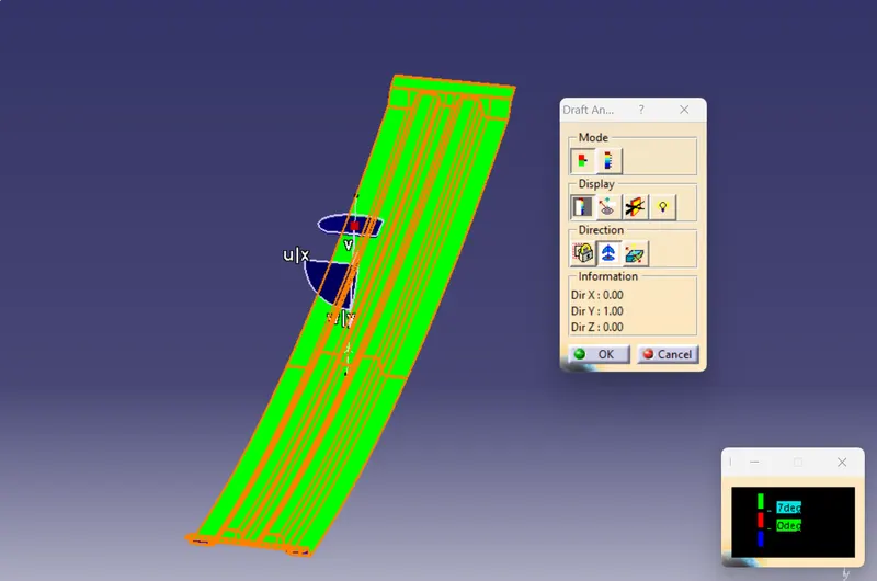
Boow Roof 02:-
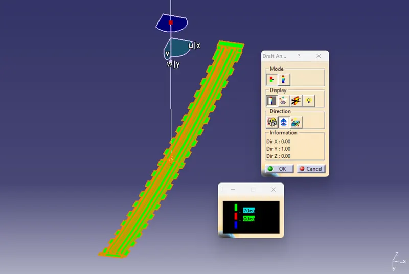
Rear Roof:-
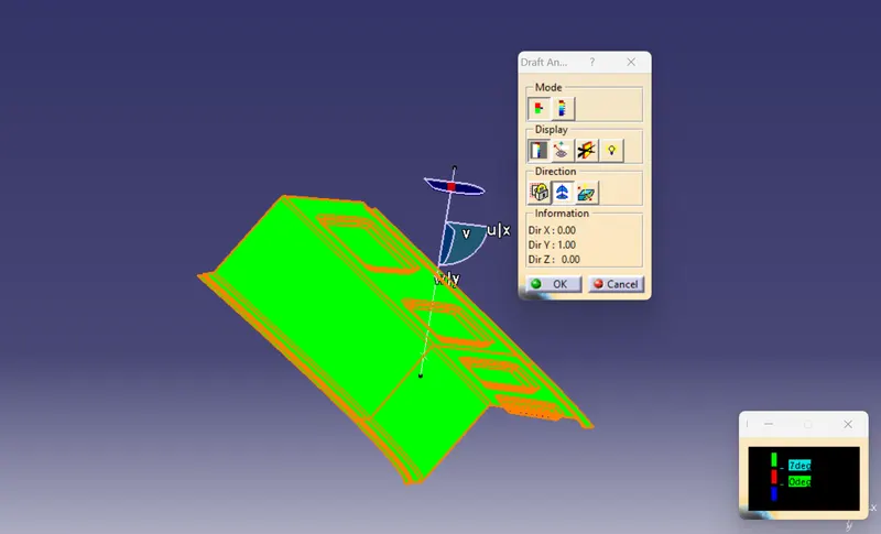
By Draft analysis all parts came positive
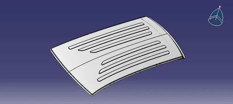
Assembly Model:-
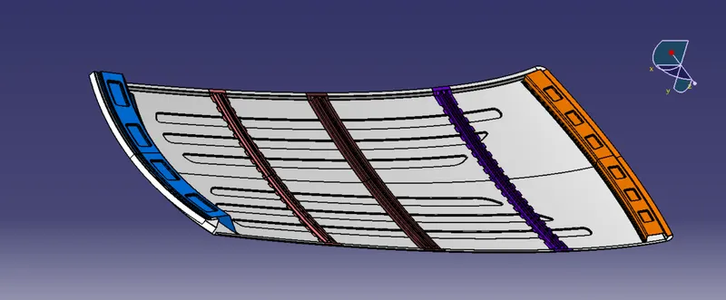
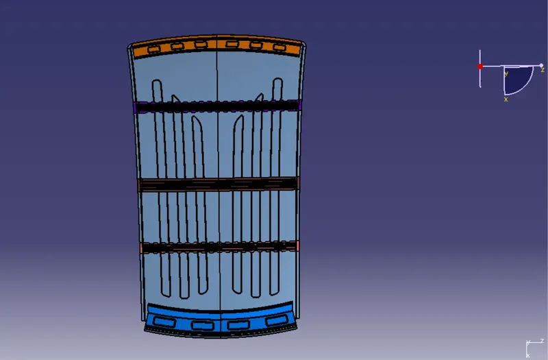
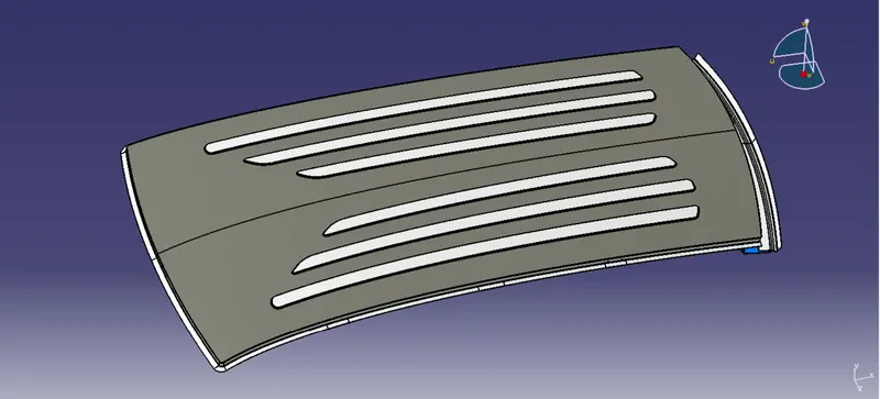
Section Views:-
Front Roof:-
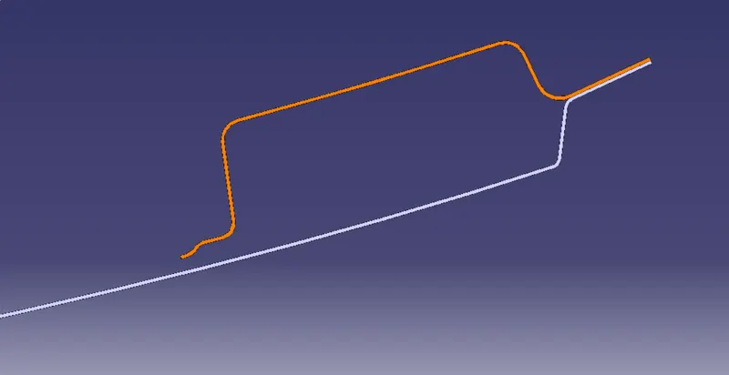
Boow Roof 01:-
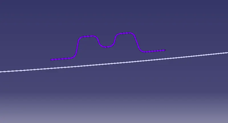
Center Roof:-
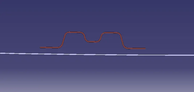
Boow Roof 02:-
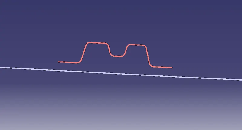
Rear Roof:-
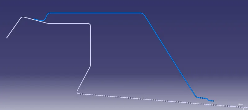
Learning Outcomes:-
1. Learned how to create rails as per the master design.
2.Learned how to calculate and what are the criteria for the Heat Distortion and Snow Load Conditions