Week 8 - Challenge 1 - Base Bracket Design
Week 8 - Challenge 1 - Base Bracket Design
AIM:- To create a Base Bracket Plastic Component using a Class 'A' Surface and by using the Closed Surface Feature to create a solid part from the surface.
OBJECTIVE:-
- To create a Plastic Surface Using Class A surface.
- To create Tooling Axis for Class A surface to check draft angle for Draft analysis.
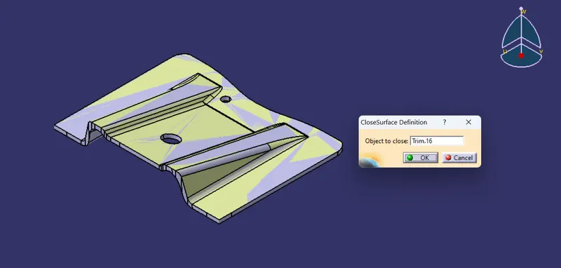
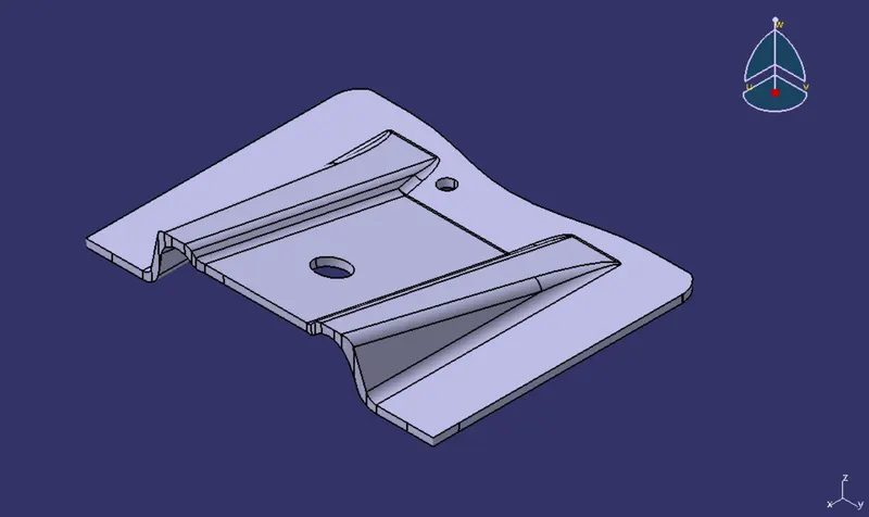
- To create solid model from the Surface Using Closed Surface Feature.
- To Draft analysis of solid part using draft tooling axis.
Draft Analysis :-
The Draft Analysis command enables you to detect if the part you drafted will be easily removed. This type of analysis is performed based on color ranges identifying zones on the analyzed element where the deviation from the draft direction at any point corresponds to specified values.
In the molding process the molded parts have to eject from the die so there are some issues while removing the molded parts it may get sticky with the die, or while removing chances to get damaged, so we need to set up is the draft angle this draft angle helps the molded parts to eject from the die easily. the standard of OEM for the plastic components draft angle should be in 3 degrees and if it is sheet metal component 7 degree should be the draft angle, This draft is get analyzed and ensuring the part is with proper draft angles.
OEM Rules for Features Draft Analysis
The truth is no single draft angle can be applied to all part designs. Factors like wall thickness, material selection, ejection, shrink rates, finish/texture, wall depth, and manufacturing capabilities all come into play. But fear not, some simple rules can be followed that can help.
When designing a part, apply as much draft angle as possible a general rule of thumb is 1 degree of draft per 1 inch of cavity depth, but that can change with the aforementioned factors. Try following these general guidelines:
- 0.5 degrees on all vertical faces is strongly advised.
- 1 to 2 degrees works very well in most situations.
- 3 degrees is minimum for a shutoff (metal sliding on metal).
- 3 degrees is required for light texture.
- 5 or more degrees is required for heavy texture.
CLASS A SURFACE
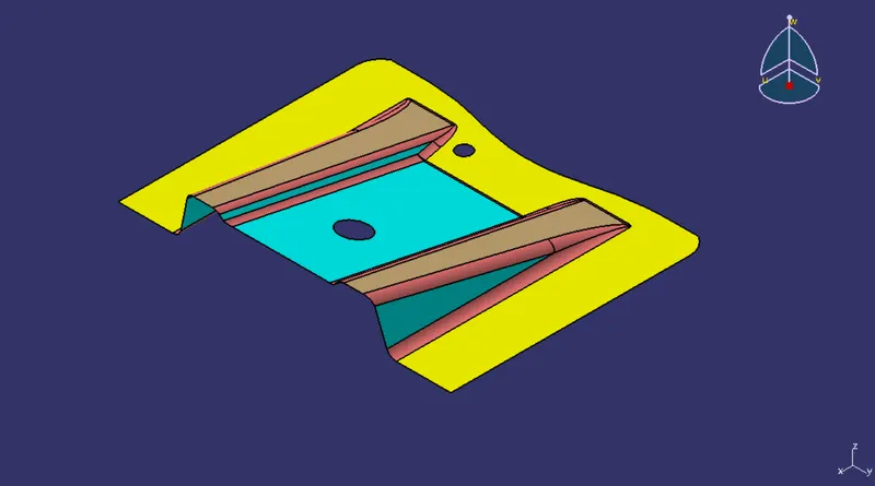
We have to first check the given Class A Surface for continuity this is done by using JOIN Feature or Boundry feature.
JOIN
The Class A Surface are Checked Visually by using the Join Feature or by using the boundary feature the Class A surface are selceted and Disassembled the Surface to check the surface are created without the gaps.
The Class A Surface should be created without the boundary Gaps. By using the Join Definition with the Merging distance of 0.001 mm the Class A surface are Joined Together to check the connectivity.
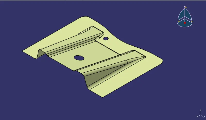
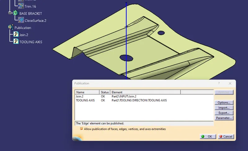
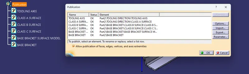
PUBLISHING THE CLASS A SURFACE:
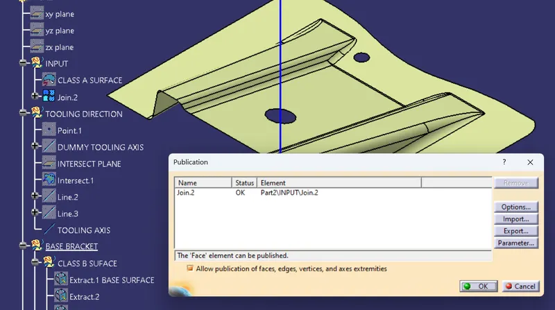
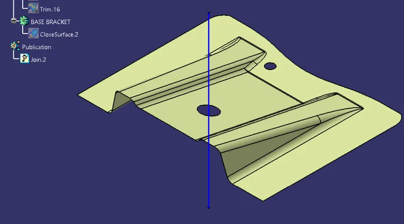
By using the Publication option the Class A Surface are Published. The Publication is used to retrive the Class A surface in the easier way to use from the Structured Tree Implementation.
TOOLING AXIS
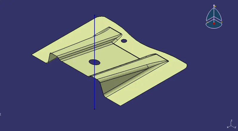
tooling axiis is created in the direction where the part is ejected by the mould.
For creating Tooling axis first we have to intersect the given Class A surface and then we have to draw to lines on each side by using bisecting line the tooling axis is obtained as shown in the below figure.
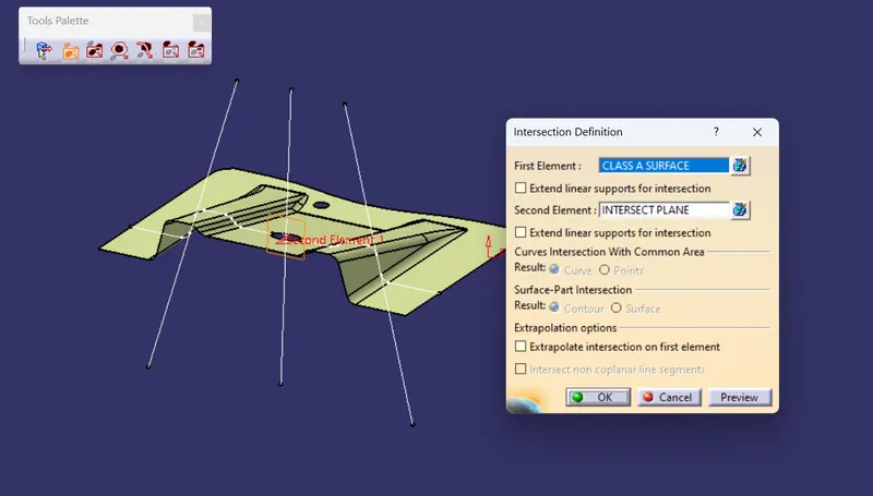
the line below shown is Tooling Axis
PUBLISH TOOLING AXIS
DRAFT ANALYSIS OF CLASS A SURFACE
DRAFT ANAYSIS:
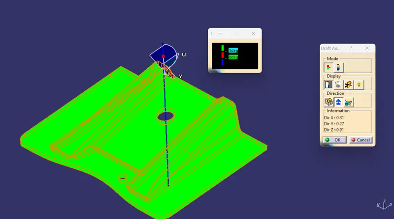
For a Class A Surface, The Draft analysis are to be performed in order to meeting te requirement of the draft angle to the required Tooling Axis. For Plastic component the Minimum angle required for the daft to be 3 degrees.
The Direction compass are to be selected and placed it on the Main Tooling Axis line and the comass are been locked using the lock feature in te direction.
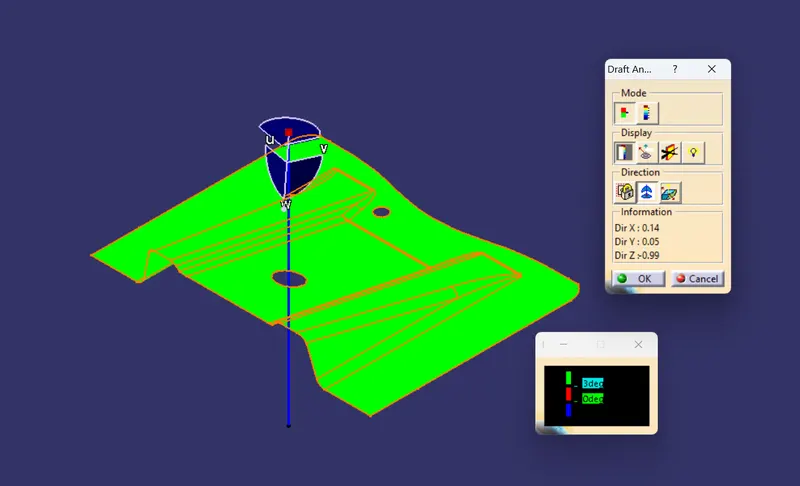
In the Display window the clour code varients are been selected, to know the range of the draft in the Class A surface. In the Display Window the colour varient shows,
- For 3 degeree - Green Colour Varient (Positive)
- For 0 degeree - Red colour varient.
- For Negative degeree- Blue colour Varient.
By Using the pointer feature in the Display the draft are been analysed for each individual points. The points perpendicular to the toling axis are displayed as 90 Degeree Direction and the Rib faces are analysed as 15.102 degeree angle.
The drafting are been performed in both the core and cavity side of Class A Surface. The Green colour Implies the draft angle are in the positive region. if The draft angle are been inverted the colour of the surface are imled as Blue colour.
CREATING CLASS B SURFACE
OFF SET AND EXTRPOL

TRIM
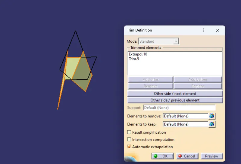
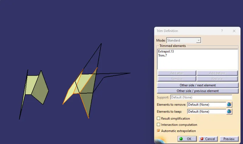
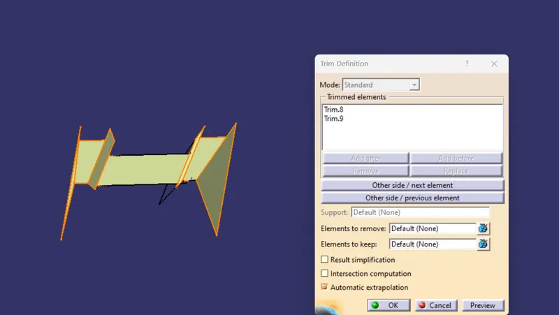
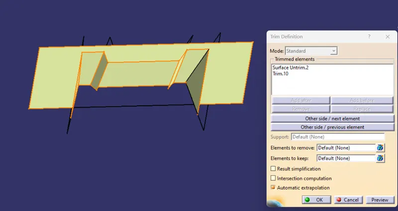
FINAL CLASS B SURFACE
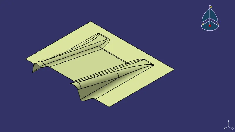
CREATING CLASS C SURFACE
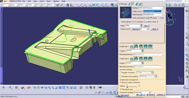
By using sweep Class A and Class B , class c surface created and trim is applied to get surface model.
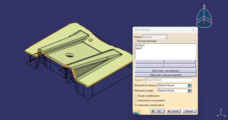
BASE BRACKET SURFACE MODEL
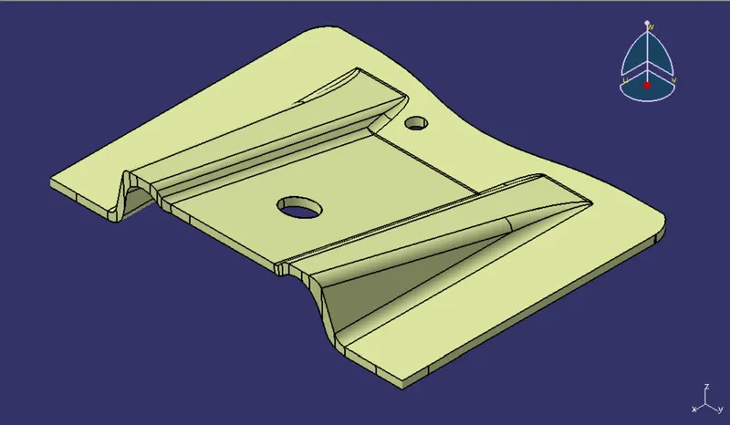
Close Surface Feature
DRAFT ANALYSIS OF FINAL MODEL
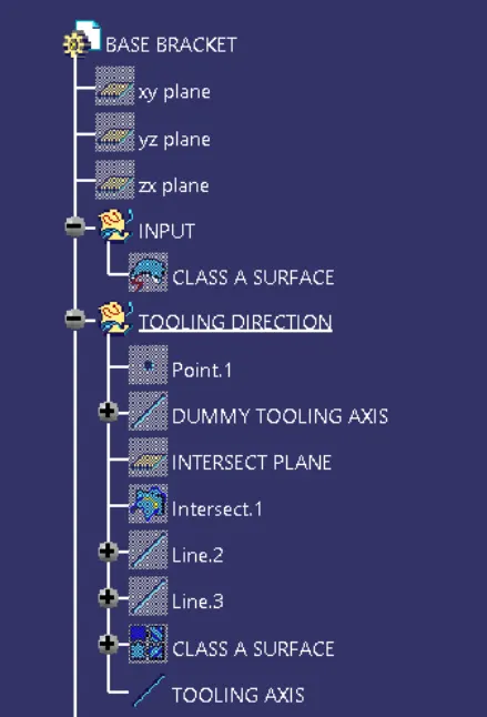
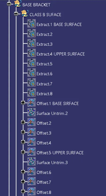
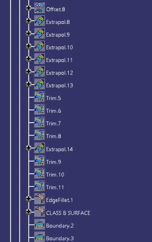
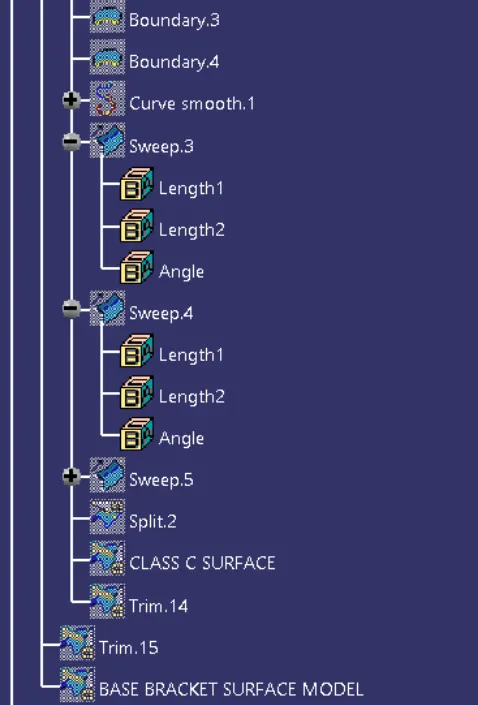
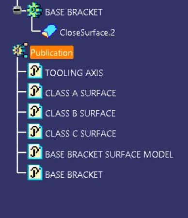
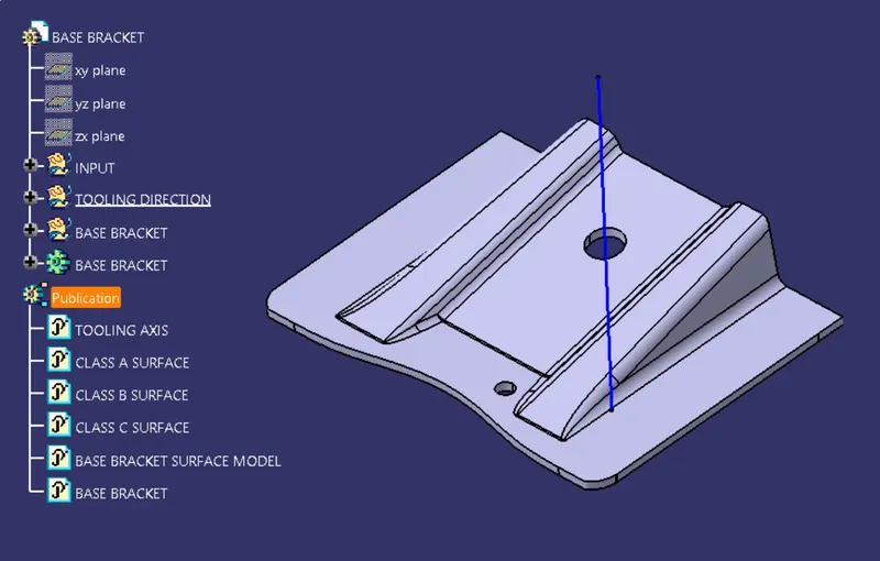
TREE STRUCTURE
CONCLUSION:
- The Base Bracket Plastic Part Component using the Class 'A' surface are Created.
- The Tooling axis for a class 'A' Surface, which meeting the requirement of the draft angle are analysed and perfrmed.
- The solid model from the surface are created by using the Closed Surface Feature.
- The detailed report which explains the Draft analysis and Tooling Axis cration and colour scale varient are explained.
- The Class A, B and C surfaces are Published using the publication option.
- The expanded Tree Structure for the Geometrical Sets are explored .
- The expanded tree structure for part design are explored.
- The 3D part Model with various orientations are attached.