Week 8 - Challenge 6 - Core & Cavity Design
Challenge 6 - Core & Cavity Design
Aim: To create core and cavity block for switch Bezel considering all plastic design rules.
Steps Followed:
- Creating parting Surface
- Creating Core Side
- Creating cavity side.
Parting Surface:
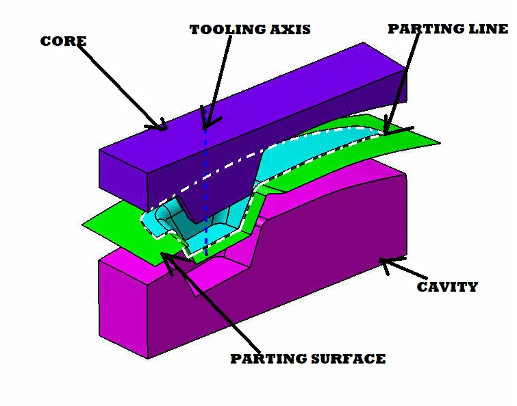
Generally, injection mold has two major components: the movable halves and fixed halve. During injection molding process these halves are pressed tightly from a sealed hollow to avoid the melt flow leakage and maintain certain holding pressure, the pressed surface called as parting surface, usually parting surface is the biggest projection outline surface of the part.
Parting surface design directly affects the product quality, ease of construction and operation of the injection mold.
Parting Line:
Parting line are where the two halves of the mold meet. This generally create a physical line on a part that is both visible and noticeable to the touch. These lines however can be hidden or minimized when placed along edges of the part. It is represented by dotted line in the below picture.
PARTING SURFACE CREATION
we have to create the parting surface at the B side surface for that we have to take SURFACE B as reference.
we have to trim between class B and Class C Surface
the surface which is voilate is CLASS C and other one is CLASS B
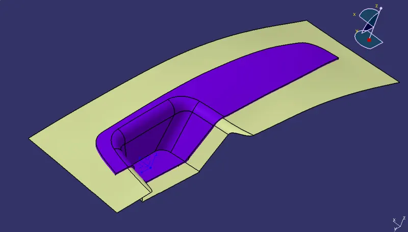
TRIM
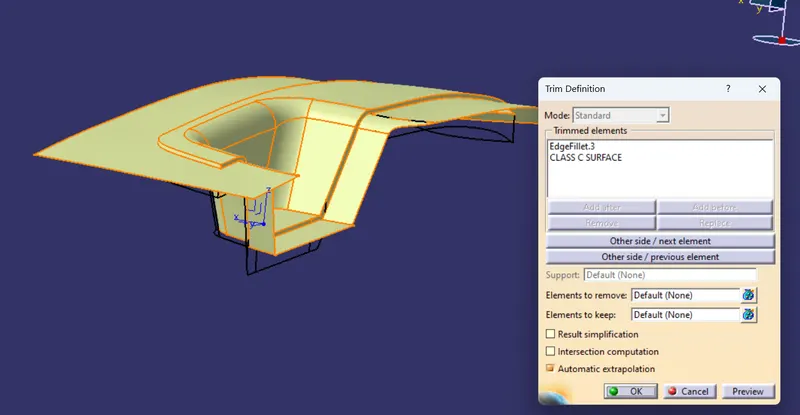
PARTING SURFACE
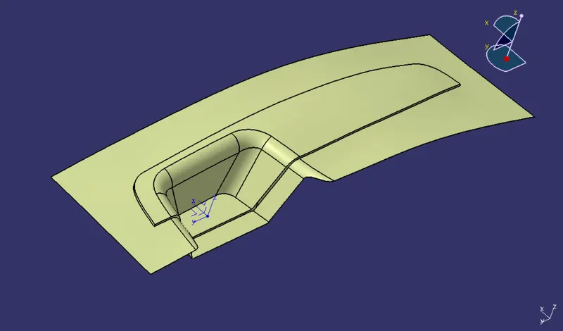
CORE CREATION
For core creation we have to create the Rectangle sketch and extrude them and trim with respect to Parting Surface
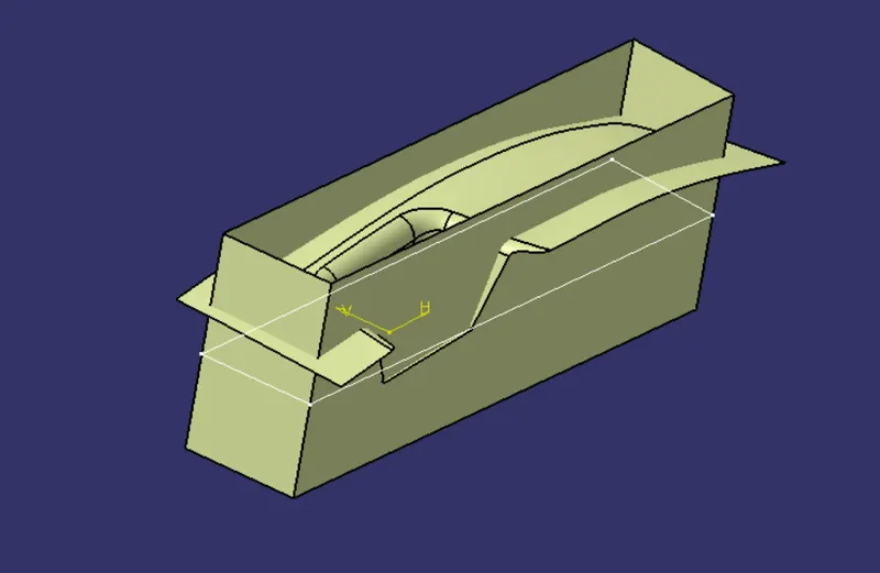
TRIM
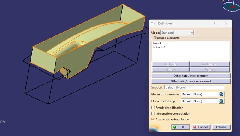
FILL
boundry is created at top portion
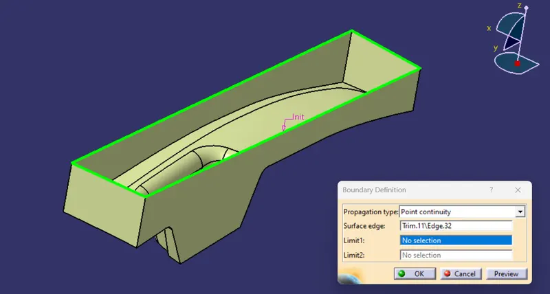
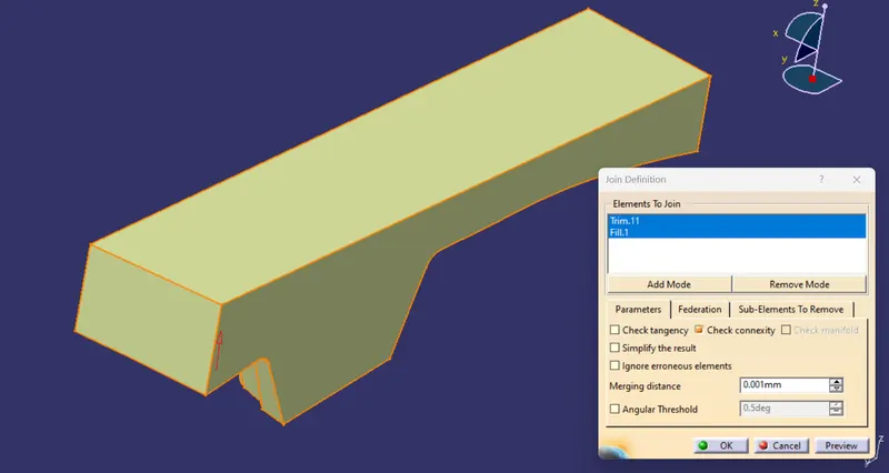
using the fill feature close the top surface and join .
CAVITY CREATION
for cavity CLASS B Surface is taken as reference to trim with extruded surface as in core.
surface which is shown in green is CLASS B surface
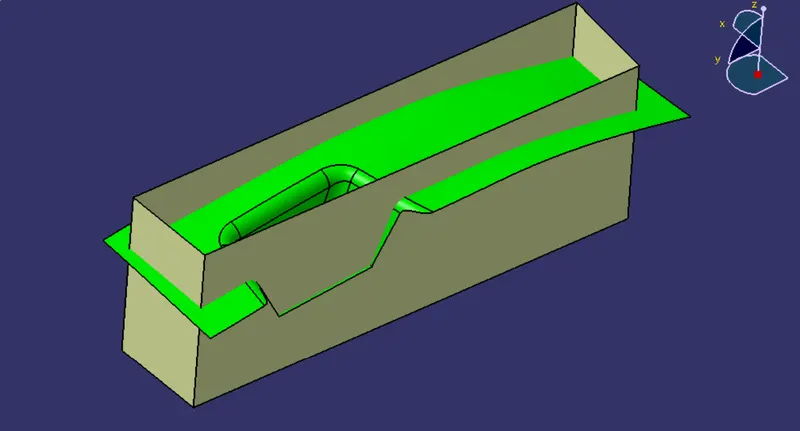
TRIM
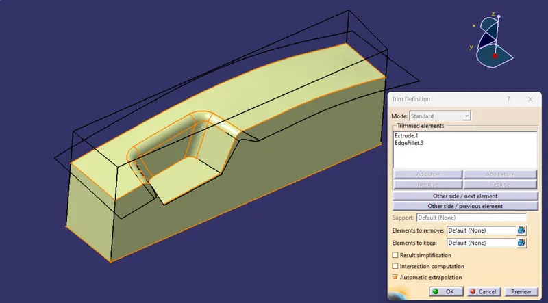
FILL
boundry is created on bottom
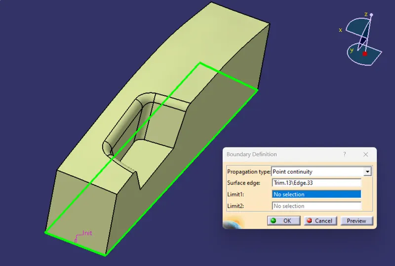
Using fill feature surface is created and joined
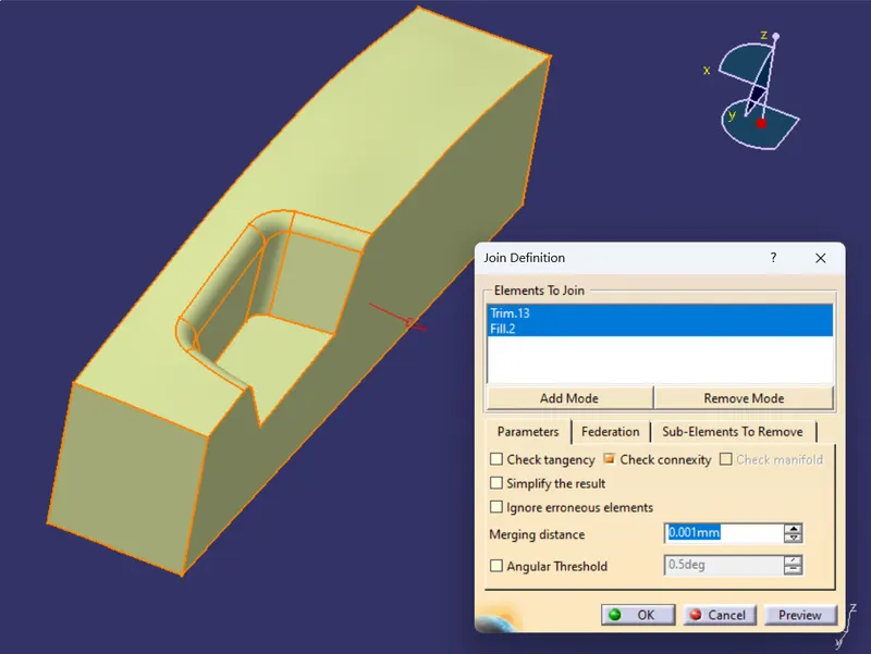
INTER SECTIONS
GREEN IS CORE
YELLOW IS CAVITY
BLACK IS PART
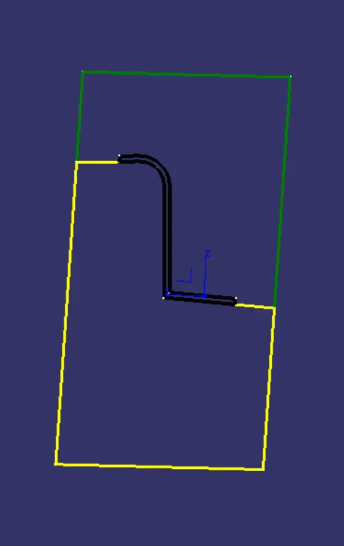
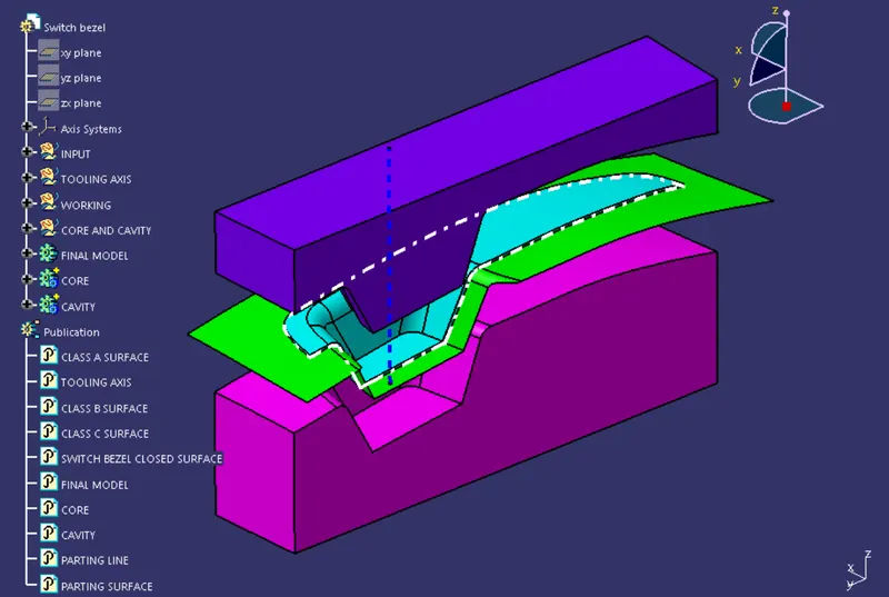
DETAIL CORE CAVITY AND PARTING SURFACE
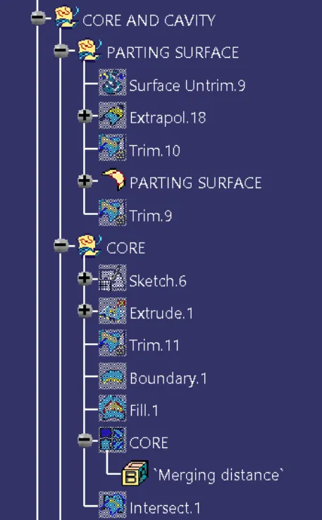
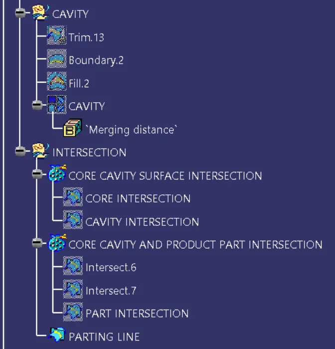
TREE STRUCTURE
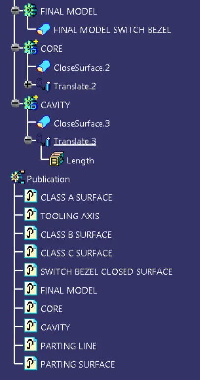
CONCLUSION
CORE AND CAVITY IS CREATED WITH REFERENCE TO TOOLING AXIS