Week 9 - Project_1 - Door Trim Lower with Engineering Features
Project_1 - Door Trim Lower with Engineering Features
Aim : To create B Side Engineering Features for Given Class A Surface.
OBJECTIVES:
- Creating Tooling Axis with proper draft.
- Creating Surfaces (B&C)
- Creating B side Engineering Features i.e Heat Stakes and 4 way locators as shown in the sample figure.
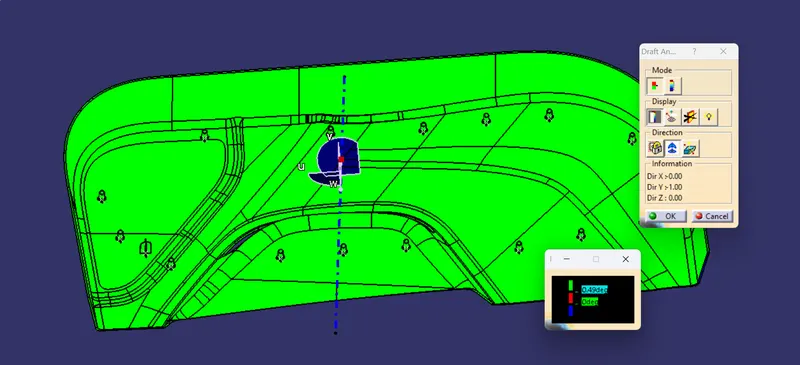
- Draft Analysis.
INPUT:
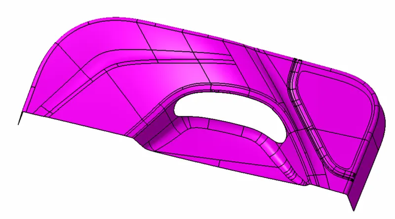
CLASS A SURFACE:
we have to check the given Class A Surface for any discontinuity present if there are means we have to modify.
so in this surface there is no such issues .
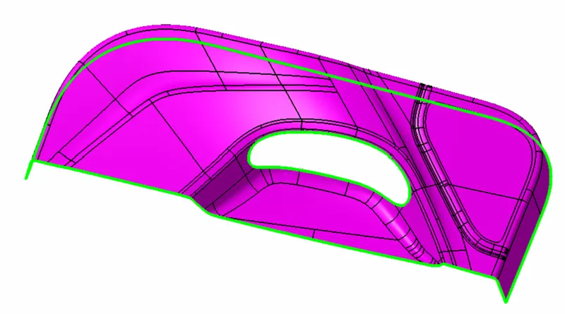
To check we have to methods one is by using boundry feature and another one is by join tool.
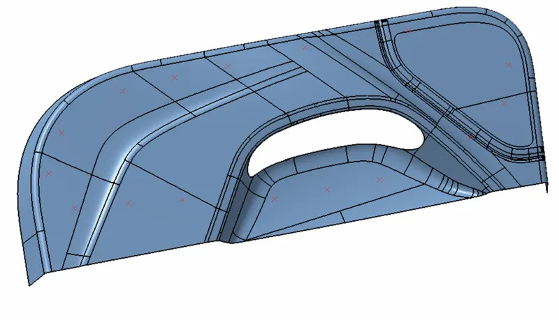
CLASS A SURFACE WITH HEAT STAKE REF POINTS
Checking by Boundry Method
Boundries are created at Edges it ok.
After checking we have to look from Manufacturing Feasibilities
TOOLING AXIS CREATION
tooling axis plays main importannt role while designing any plastic compont because the correct draft angle results in smooth operation and easy to manufacture .
if the tooling axis is not maintrd properly whole mould will be scrap. so while designing any plastic component we have keep manufacturing process in maind.
Creat points
Poiints are created on the Class A Surface at desired poisition considering Tooling Direction
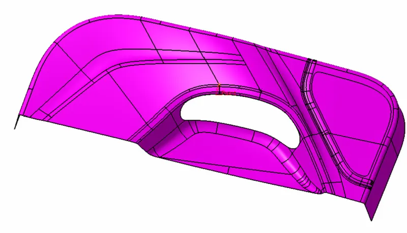
After point creation Axis System is created by the same Point,
Intersect lines are created on the surface with reference to the planes of the Axis system,
now lines are created on either ends of the intersect lines as shown in the fig
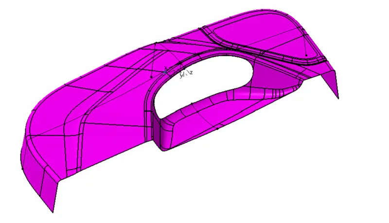
Bisecting lines are Created
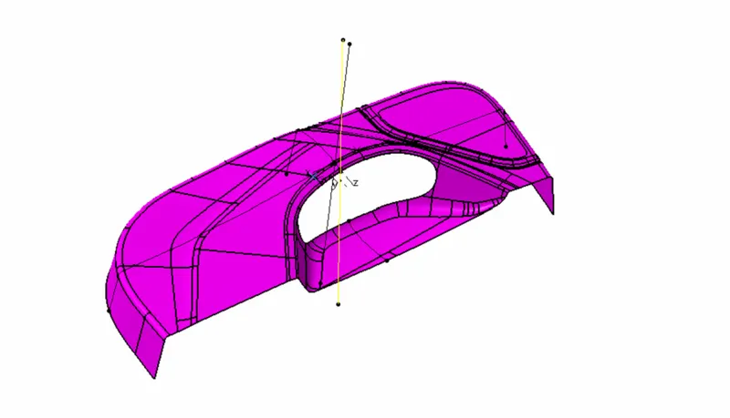
final tooling axis creation
TOOLING AXIS
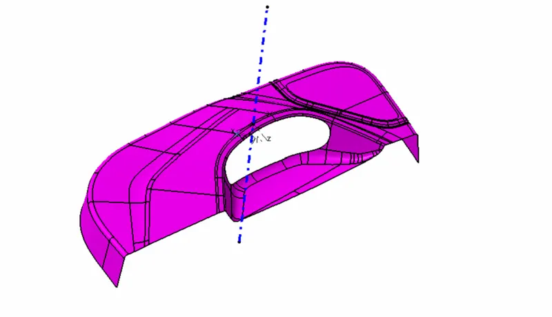
VIEW NORMAL TO TOOLING AXIS
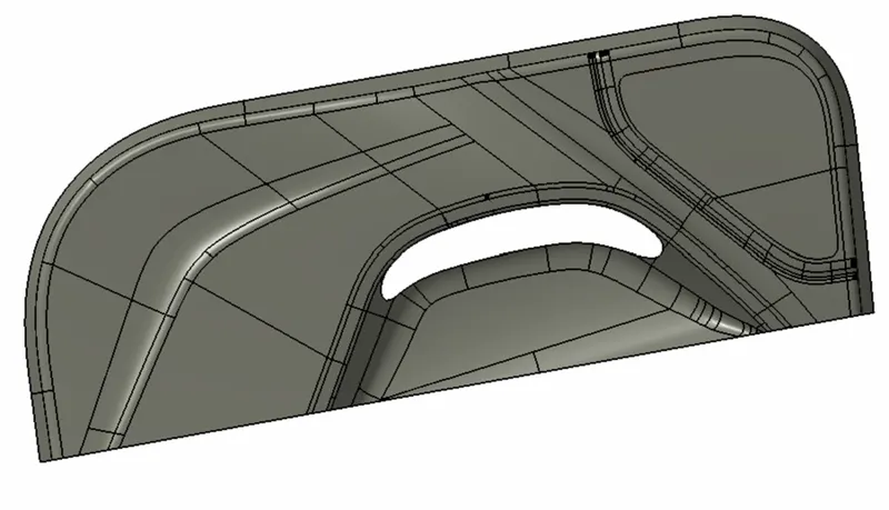
In this view we can see that all the portion are cleared by tooling direction.
B SURFACE CREATION
For creating B Surface first we need to offset the A Surface for 2.5mm by considering wall thickness
OFFSET
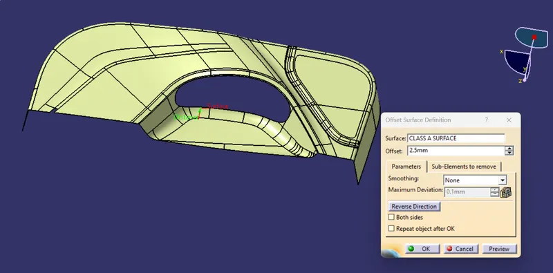
after offset there will be some surface not cleared so we need to check by using boundry feature
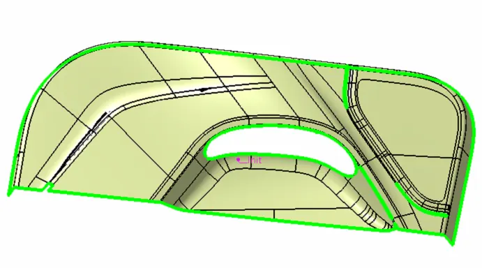
we can see the surface which are not formed correctly after the offset operation
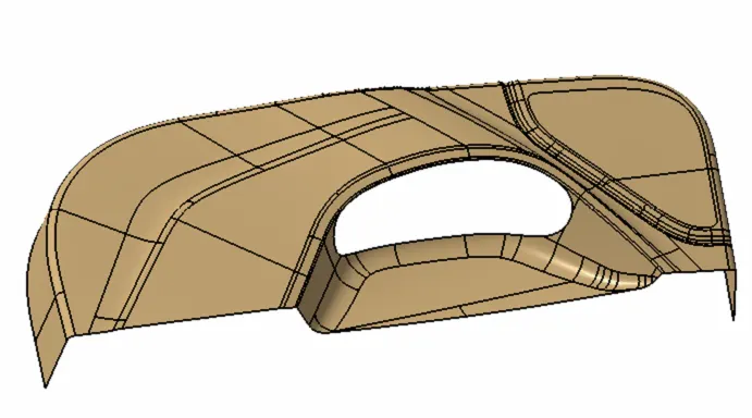
soo we need to do correction by following certain operations like Offset,Extract,Multisurface,Fill as per required.
after performing all the operations we will get B Surface as shown in the figure.
CREATING C SURFACE
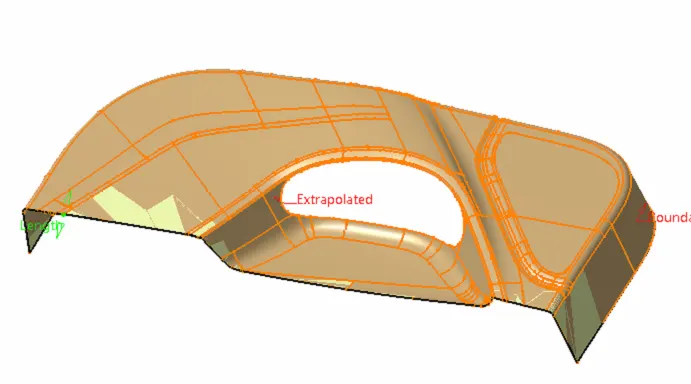
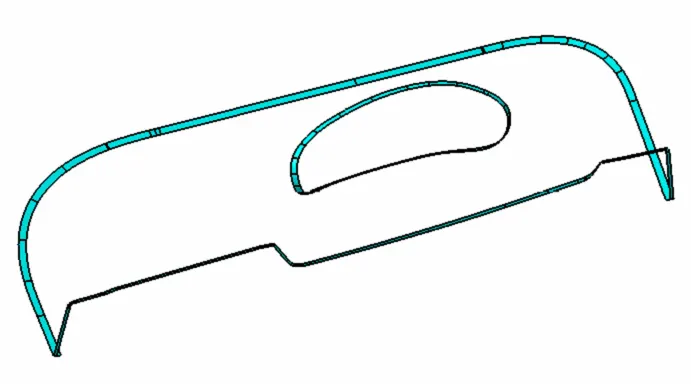
C Surface is created to join between A and B surface
For that we need to extraplote the B Surface for 0.5mm and Extract Boundries of Class A Surface to perform Sweep operation
EXTRAPLOTE
SWEEP
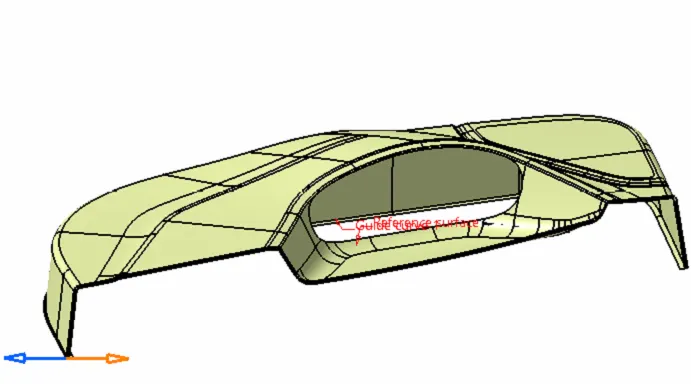
JOIN THE SWEEP
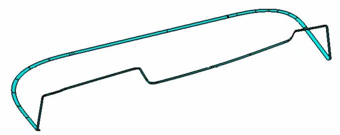
C SURFACE
CLOSED SURFACE
After generating Class C Surface we need to Trim the surface with respect to Class A Surface and B Surface
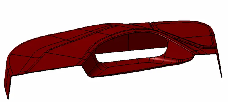
GIVING THICKNESS
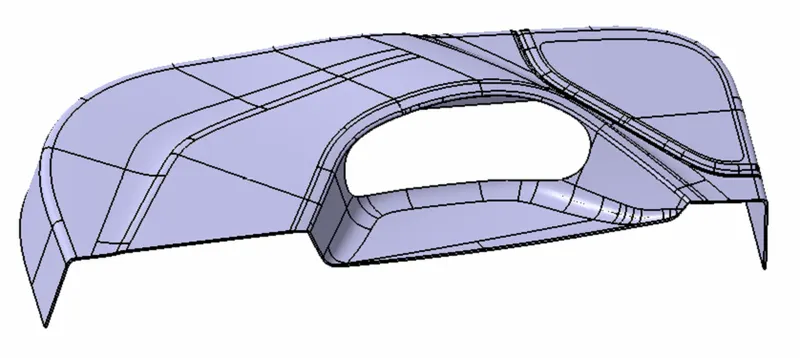
CREATING B SIDE ENGINEERING FEATURES
For creating B side features i.e Heat Stakes Ref Points are given so we need create them with ref to that points.
Reference Points
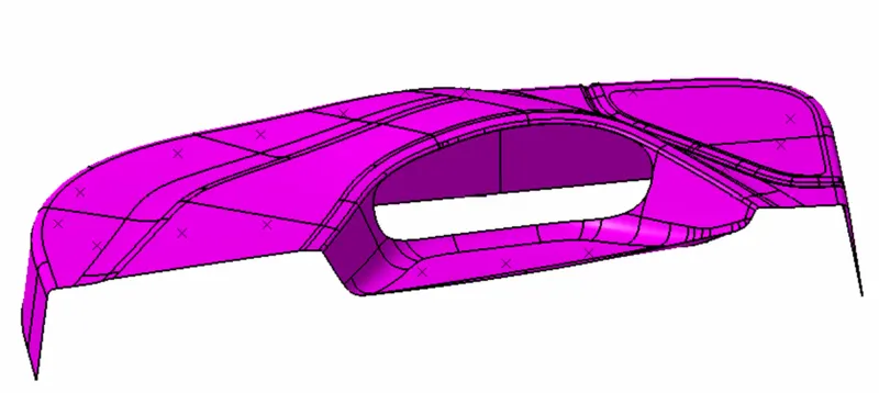
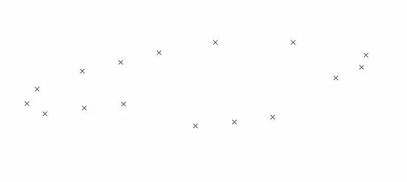
on this ref points we need to create heat stakes and Four Way Locators.
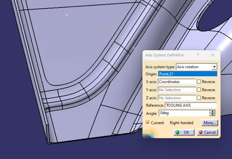
First create Axis System On one perticular point with reference t tooling axis as shon in the below fig
So that while doing Draft Analysis it Won't create any issues.
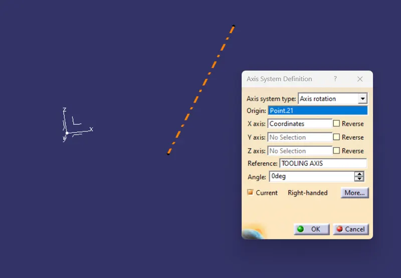
Now create Sketch on the plane of the axis system
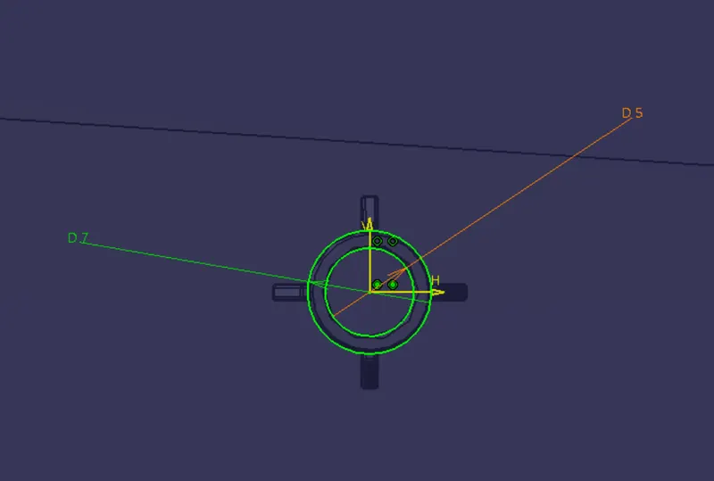
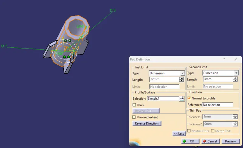
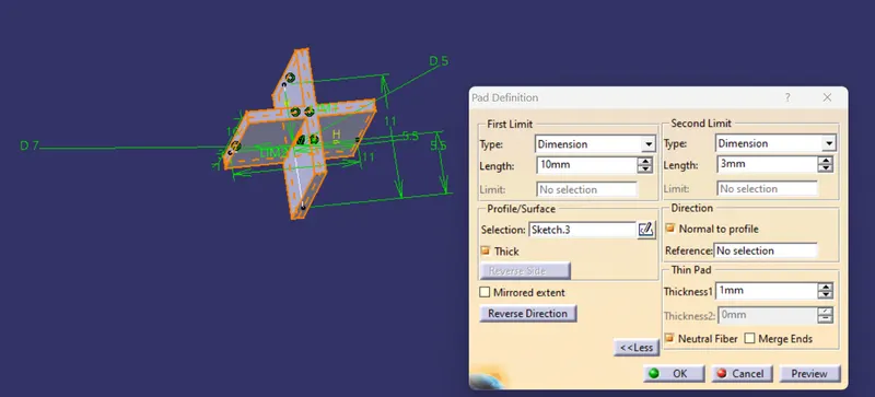
PAD
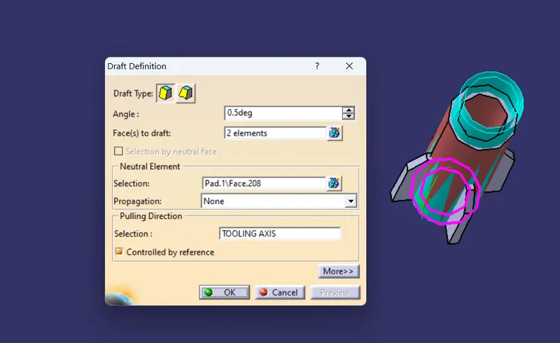
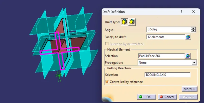
DRAFT
min draft angle is 0.5deg
CREATE RIBS
For creating Ribs we need to create part in Different Body and then using Boolean Operation we need to Unitrim with respect to heat stake body.
Sketche for Ribs
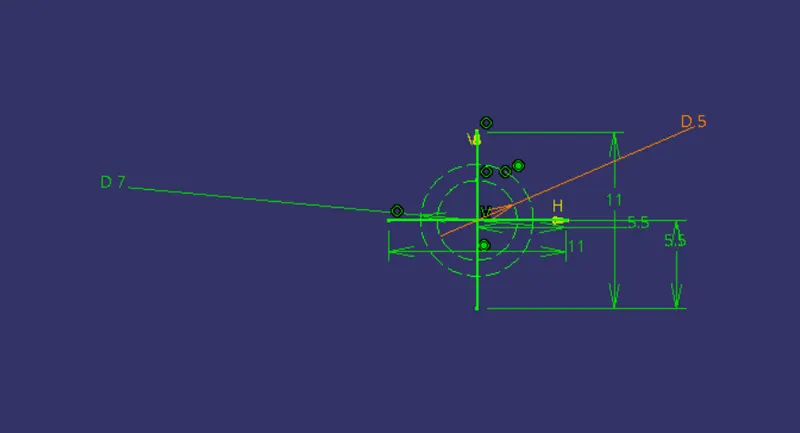
PAD
Draft
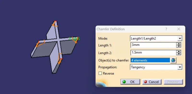
CHAMFER
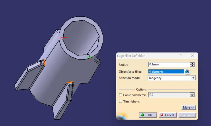
Edge fillet
BOOLEAN OPERATION
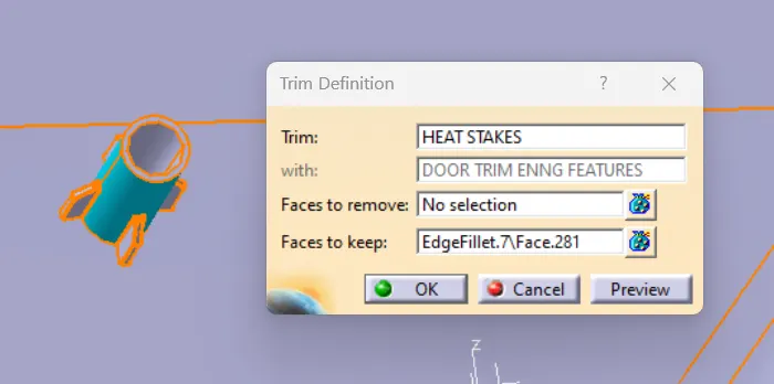
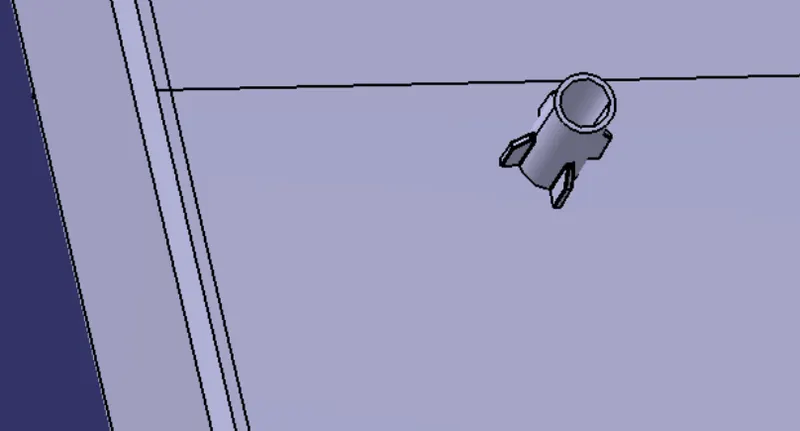
After creating Heat stakes we need to Create same at given Points for that we need to use Power Copy tool
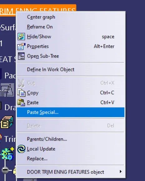
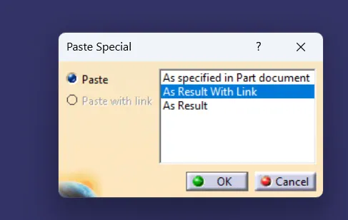
we need to copy and paste Using Paste special
COPY--> PASTE SPECIAL
As Result with link
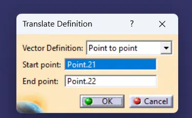
After that we need to translate the part with point to point as shown in the figure
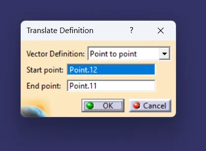
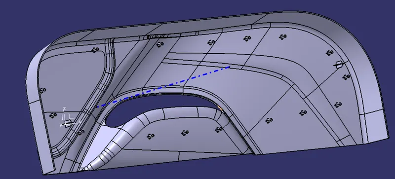
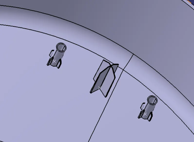
After all parts are pasted using power copy tool and translated we need to perform Boolen opetation to the Door Trim part by Union Trim
as shown in fig
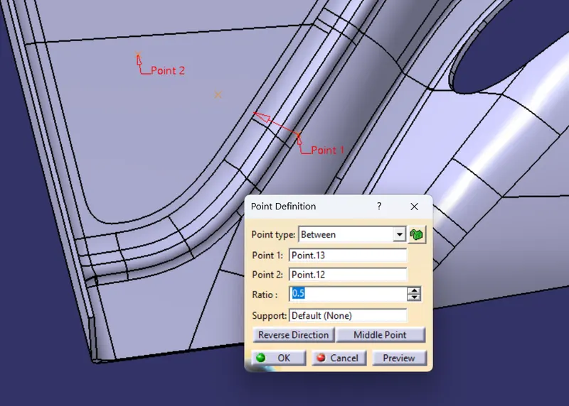
Creating way locators
create points between points using between option in point feature as shown below
create Axis System on this point with reference to tooling axis
Sketch
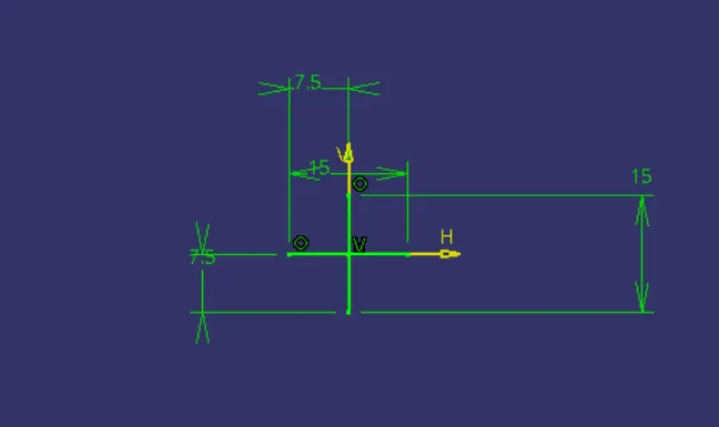
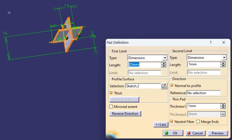
PAD
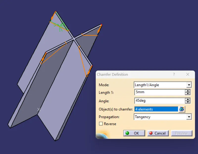
CHAMFER
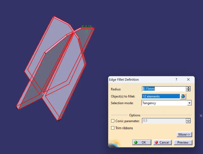
Edge fillet
Translate
By power copy generate another 4 way locator and translate to point at required location
Boolean Operation
After fully Creating 4 way Locators we need to Union Trim with respect to Door Trim
DRAFT ANALYSIS
TREE STRUCTURE
CONCLUSION
the model is created by engineering features