Project 1 Mechanical design of battery pack
Mechanical design of battery pack
Battery pack capacity: 18 kWh
Cell: ANR26650M1-B
Prepare a detailed battery pack drawing along with its enclosure. State your assumptions
EV battery pack design
The high voltage battery it is one of the most important components of an electric vehicle (EV).
The battery parameters have a significant influence on other components and attributes of the vehicle, like:
- maximum traction motor torque
- maximum regeneration brake torque
- vehicle range
- vehicle total weight
- vehicle price
- A battery consists of one or more electrochemical cells (battery cells) which are converting chemical energy into electrical energy (during discharging) and electrical energy into chemical energy (during charging). The type of elements contained within a battery and the chemical reactions during discharging-charging events define the chemistry of a battery.
- Individual battery cells are grouped together into a single mechanical and electrical unit called a battery module. The modules are electrically connected to form a battery pack.
- There are several types of batteries (chemistry) used in hybrid and electric vehicle propulsion systems but we are going to consider only Lithium-ion cells. The main reason is that Li-ion batteries have higher specific energy [Wh/kg] and specific power [W/kg] compared with other types.
Mechanical design
- Safety and reliability are the two key challenges for large-scale electrification of road transport sector. Current Li-ion battery packs are prone to failure due to reasons such as continuous transmission of mechanical vibrations, exposure to high impact forces and, thermal runaway. Robust mechanical design and battery packaging can provide greater degree of protection against all of these.
CELL Parameters (ANR26650M1-B )
- In order to choose what battery cells our pack will have; we’ll analyse several battery cells models available on the market.
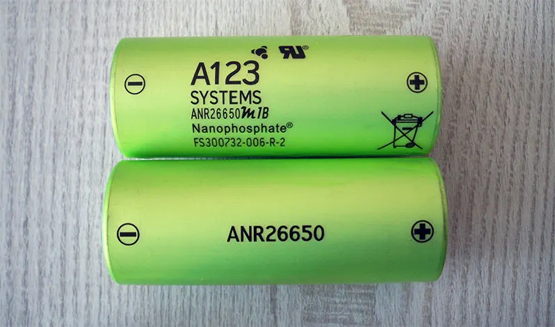
- Here, we choose the ANR26650M1-B battery model for our battery design.
.
 .
.

- Nominal capacity: 2.5Ah at 0.5C rate
Minimum capacity: 2.4Ah at 0.5C rate
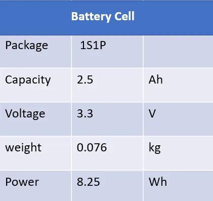
Nominal voltage: 3.3V
Charge end voltage: 3.6V
Standard charge current: 2.5A (1C)
Fast charge current: 10A (4C)
Max continuous discharge current: 25A (10C)
Max pulse discharge current (10 sec): 60A (24C)
Discharge cut-off voltage: 2.0V
AC impedance at 1KHz: 6mΩ
Weight: 76g
- High-performance Nanophosphate® lithium iron phosphate (LiFePO4) battery technology delivers high power and energy density combined with excellent safety performance and extensive life cycling in a lighter weight, more compact package.
- Cells have low-capacity loss and impedance growth over time as well as high usable energy over a wide state of charge (SOC) range, allowing systems to meet end-of-life power and energy requirements with minimal pack oversizing.
Battery pack calculation
Based on the cell parameters provided by the manufacturers, we can calculate the energy content, volume, gravimetric density and volumetric density for each cell.
| Manufacturer | A123-Systems |
| Type | cylindrical |
| Model | ANR26650m1-B |
| Source | [5] |
| Length [m] | 0.065 |
| Diameter [m] | 0.026 |
| Height [m] | 0 |
| Width [m] | 0 |
| Thickness [m] | 0 |
| Mass [kg] | 0.076 |
| Capacity [Ah] | 2.5 |
| Voltage [V] | 3.3 |
| C-rate (cont.) | 10 |
| C-rate (peak) | 24 |
1. Volume of each cell, Vc [m3]
Vc =π⋅(Dc)24⋅Lc">Vc =π⋅(Dc)24⋅LcVc =π⋅(Dc)24⋅Lc
Lc - battery cell length [m]
Dc - battery cell diameter [m]
Vc = (π * 0.0262 /4)* 0.065 = 0.034510 m3
2. Battery cell energy, Ebc [Wh]
Ec = Cc .Uc
Cc = Battery cell Capacity[Ah]
Uc = Battery Cell Voltage[m]
Ec = 2.5*3.3 = 8.25Wh
3.Battery cell energy density
Volumetric energy desity,Uv[Wh/m3]
uV = Ec/Vc
Uv = 8.25 / 0.034510 = 108.55Wh/m3
Gravimetric energy density

Ug = 8.25 / 0.076 = 239.06 wh/Kg
* with the above cell parameter and the core reqirments for the battery(Nominal voltage,avarage energy consumption and vechicle range).We calculate the main parameters of the high vlotage battery.
High Voltage battery
1.The battery Pack total energy Eb [Wh]
- The required battery pack total energy Eb[Wh] is calculated as the product betwen the average energy consumption E avg [Kh /Km] and vechicle range Dv[km]
- Here well desigh the high voltage battery pack of 18Kwh for avechicle range of 250Km
Therfore Eb = 18Kwh Dv = 200km
Eavg = Eb /Dv = 18000 / 200 = 90Wh/km
2.The Battery pack Voltage Ub[V]
- The Battery PAck voltage is considered to be 300V high voltage
Ub = 300V
we are going to consider that the battery pack is madeup only from serveral Strings connected in parallel
3.The number of battery cell connected in series Ns
- Ns in a string is calculated by dividing the nominal battery pack voltage Ub [V] to the voltage of each battery Cells Uc [v].The number of strings must be an integer.
Ns = Ub /Uc
Ns 300/3.3 = 90.90 = 91s
4.The energy content of a string Es[Wh]
- Eb is equal with the product between the number of battery cells connected in series Ns [-] and the energy of a battery cell Ec [Wh].
Es = ns .Ec
Es = 91 * 8.25 = 750.75 Wh
5.THe number of battery cells connected in parallel Np
- The total number of strings of the battery pack Np [-] is calculated by dividing the battery pack total energy Eb [Wh] to the energy content of a string Es [Wh]. The number of strings must be an integer. Therefore, the result of the calculation is rounded to the higher integer.
Np = Eb / Es
Np = 18000 /750.75 = 23.9 24p
We can now recalculate the battery pack total energy Eb [Wh] as the product between number of strings Np [-] and the energy content of each string Es [Wh].
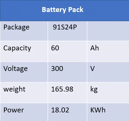
Eb = 24 * 750.75 =18.02Kwh
6.The Battery pack Capacity Cb[Ah]
- Cb is calculated as the product between the number of strings Np [-] and the capacity of the battery cell Cc [Ah].
Cb = Ns .Cc
Cb = 24*2.5 = 60Ah
7. The total number of cells of the battery pack Nb
- The total number of cells of the battery pack is calculated as the product between the number of strings Np [-] and the number of cells in a string Ns [-]
Nb = Np . Ns
Nb = 91.24 = 2184 cells
The size and mass of the high voltage battery are very important parameter to consider when designing a battery electric vehicle (BEV). In this example we are going to calculate the volume of the battery pack considering only the battery cells. In reality there are other factors to consider, like:electronic circuits, cooling circuit, battery casing, wiring, etc.
8.The volume of the battery pack (cells only) Vb [m3]
- The volume of the battery pack (cells only) is the product between the total number of cells Nb [-] and the mass of each battery cell Vc [m3].
- This vvolume is only used to estimate the final volume of the battery pack, since it does not take into account the auxiliary components/systems of the battery.
Vb = Nb .Vc
Vb = 2184 *0.034510 = 75.37M^3
- The volume can be also calculated function of number of strings and number of cells in a string. This calculation method is more appropriate for cylindrical cell, since the volume occupied by a cylindrical cell must take into account the air gap between cells.
10.The String peak Current Ispc [A]
- The string peak current is the product between the peak C-rate of the battery cell C-ratecp [h-1] and the battery cell capacity Cb [Ah]
I sp = C rate Cp . cb
Isp =24*2.5 = 60A
11.The battery pack peak current Ibp [A]
- The battery pack peak current is the product between the string peak current Ispc [A] and the number of strings of the battery pack Np [-].
Ibp = Isp .Np
Ibp =60 * 24 1440A
12.The battery pack peak power Pbp [W]
- The battery pack peak power Pbp [W] is the product between battery pack peak current Ibp [A] and the battery pack voltage Ub [V]
Pbp = Ibp . Ub
Pbp = 1400*300 432Kw
13.The string continuous current Isc [A]
- The string continuous current is the product between the continuous C-rate of the battery cell C-ratebc [h-1] and the battery cell capacity Cb [Ah].
Isc = Crate .Cb
Isc = 10 *2.5 25 A
14. The battery pack continuous current Ibc [A]
- The battery pack continuous current is the product between the string continuous current Isc [A] and the number of strings of the battery pack Np.
Ibp = Isc .Np
Ibp = 25*24 = 600A
15.The battery pack continuous power Pbc [W]
- The battery pack continuous power is the product between battery pack continuous current Ibc [A] and the battery pack voltage Ub [V].
Pbc = Ibc .Up
Pbc = 900*300 180Kw
The mass and volume are calculated only at cell level, taking into account the cell dimensions and mass. The battery pack which will be in the vehicle will have additional components (wires, electronic components, soldering, case, etc.), which will increase both the final volume and mass
The Result
| Manufacturer | A123-Systems |
| No of cells in string [-] | 91 |
| String energy [Wh] | 750.75 |
| No of strings [-] | 24 |
| BP energy [kWh] | 180.2 |
| BP capacity [Ah] | 60 |
| No total cells [-] | 2184 |
| BP mass [kg]* | 165.98 |
| BP volume [l]* | 75.37 |
| BP peak current [A] | 1440 |
| BP peak power [kW] | 432 |
| BP continuous current [A] | 900 |
| BP continuous power [kW] | 180 |
BATTERY MODULE
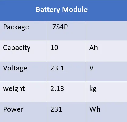
- The Battery Requirements is 18.02KWh battery pack, the required configuration of the pack is 91S24P, i.e., 91 series, and 2184 cells connected in parallel.
- To build such a large grid, we need to slip the battery packs into the battery module, which reduce the complexity of monitoring and optimizing battery management and minimizing battery damage
So, we are Splitting the 91S24P 2184cells into no of 7S4P Cell Modules
No of Cells in Battery Pack, 91 * 24 = 2184 cells
No of Cells in a Battery Module, 7 * 4 = 28 cells
No of Modules = 2184/28 = 78 no of Modules
Modules Configuration = 13 x 6 = 78
Cell Configuration in a module = 7S4P
no of Modules in the Battery Pack = 78
Module Configuration in the Battery pack = 13 x 6
CELL DIMENTIONS
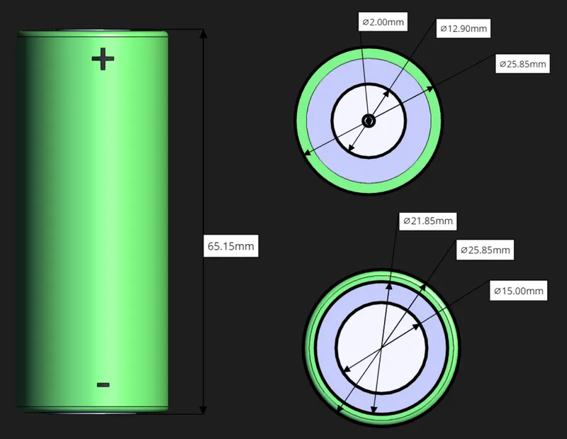
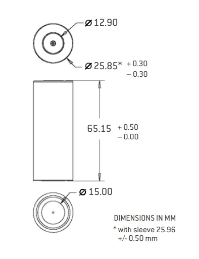
Length 65.15+0.05 mm
Diameter 25.85±0.30 mm
Weight 0.076 Kg
Cell holder:
- Each Cell holder can hold up to 4 battery cells, and can hold the battery pack with more holders connecting together, holder improves the stability of the battery back and reduces vibrations.
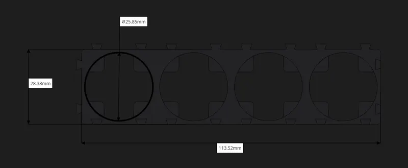
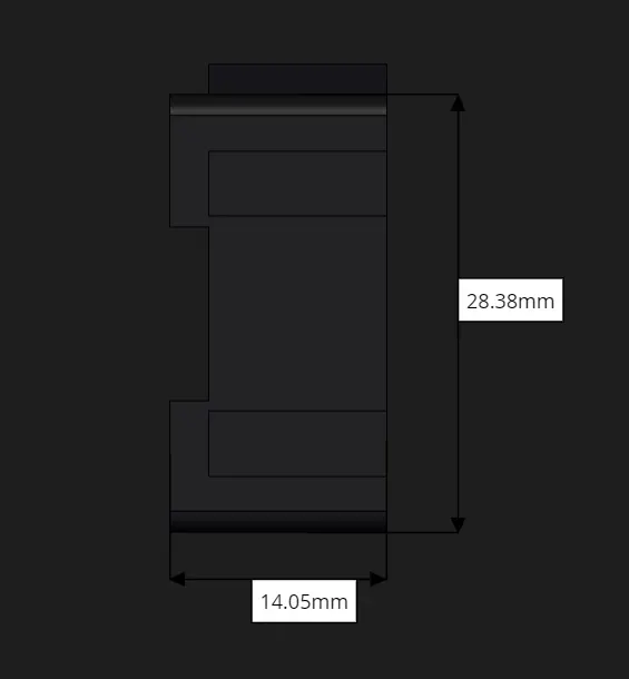
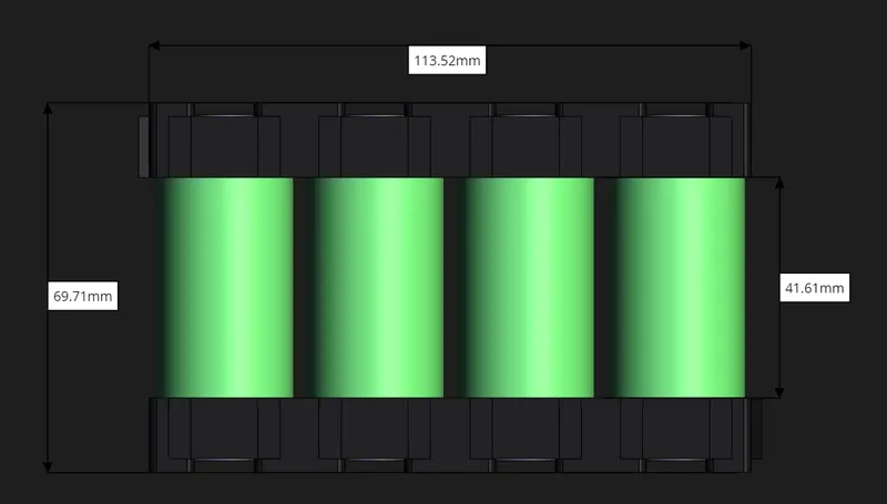
- By connecting more holders to each other we can make the battery grid according to the required battery back configuration.
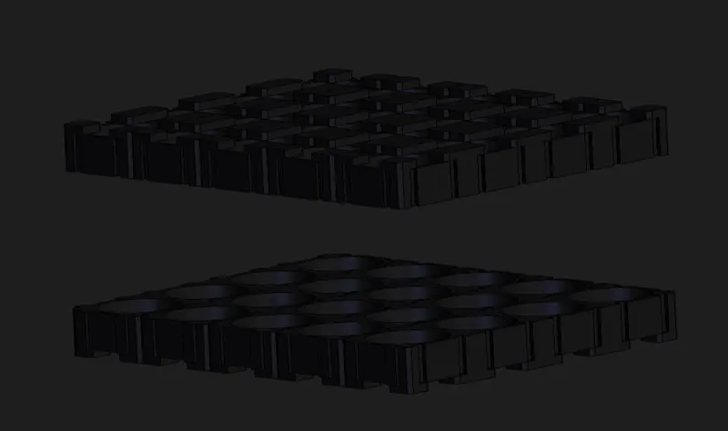 .
.

- Here we are going to make 7S4P battery, therefore a battery holder can use to hold 4cells of parallel connected cells and 7 such holders can be implement to achieve 7S4P Battery module.
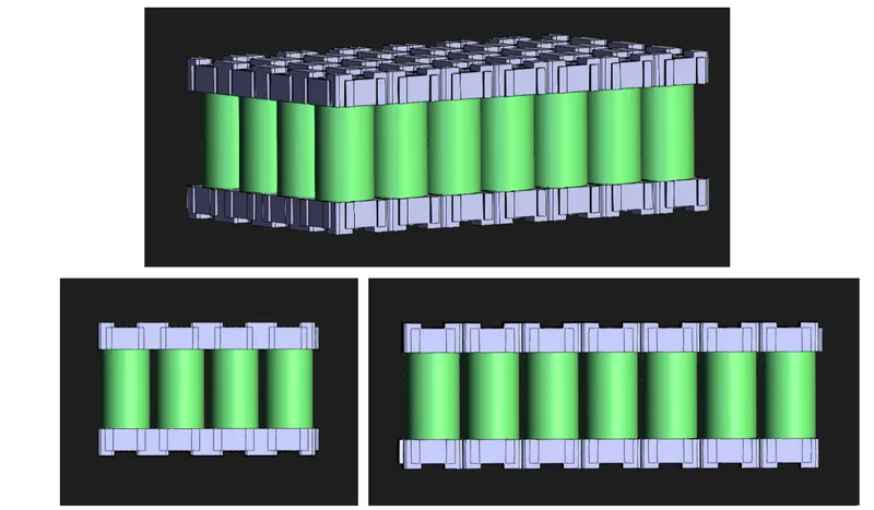
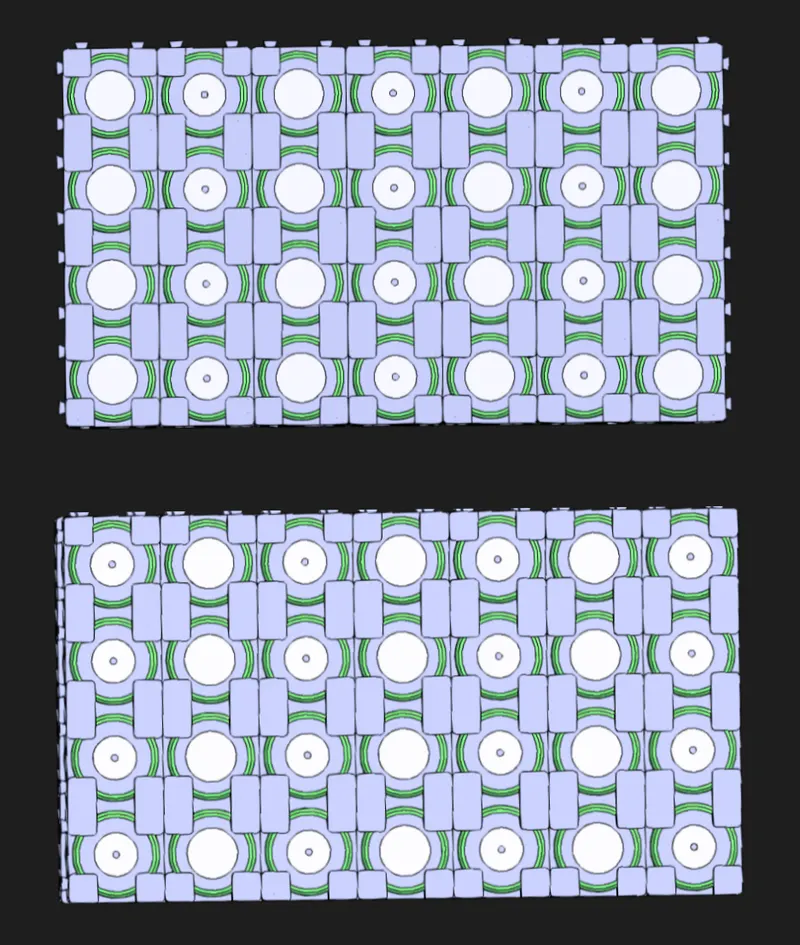
- The holder is designed to have adequate air gap between each cell and can be used to implement thermal management strips or plates
Dimensions:
Length = 198.66mm
Width = 113.52 mm
Height = 69.71mm
Weight = 0.076 * 28 2.13kg
Electric Connection:
Nickle Strips/Tabs:
- Conductivemetal strips are spot welded between all the cells of an electric bicycle battery pack. Nickel is the material of choice due to its low relative resistance and ease of spot welding.
- Pure nickel strip is ideal for use in the building of batteries. As the alloy has high corrosion resistance, can be efficiently spot welded and soldered and offers good conductivity with low electrical sensitivity, it allows battery sources to perform well, even in highly corrosive environments
- Resistance Spot welding, micro TIG welding, and laser welding processes all enable high quality volume production. The selection of one technology over another is usually made based on the application’s specific requirements and the alignment of the technology to these needs.

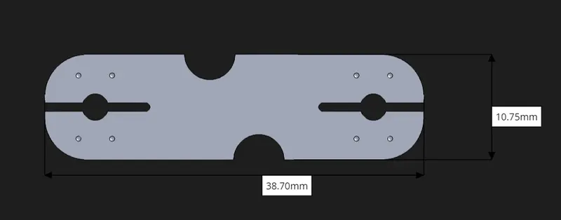
- We use a nickel tab to connect the cells to make a battery pack. It has 4 markings, which can be spot welded between the battery and the trip using any spot weld technique.
- The thickness of the strip is 0.3 mm, length and width are 38.7 mm and 10.7 mm.
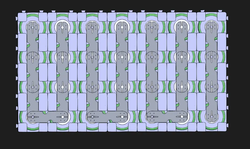
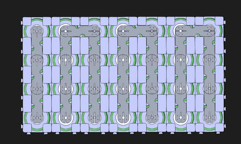
- Connections are made by connecting parallel and in series.
BMS ( Battery Management System)
- A Battery Management System (BMS) is said to be the brain of a battery pack. The BMS is a set of electronics that monitors and manages all of the battery’s performance. Most importantly, it keeps the battery from operating outside of its safety margins.
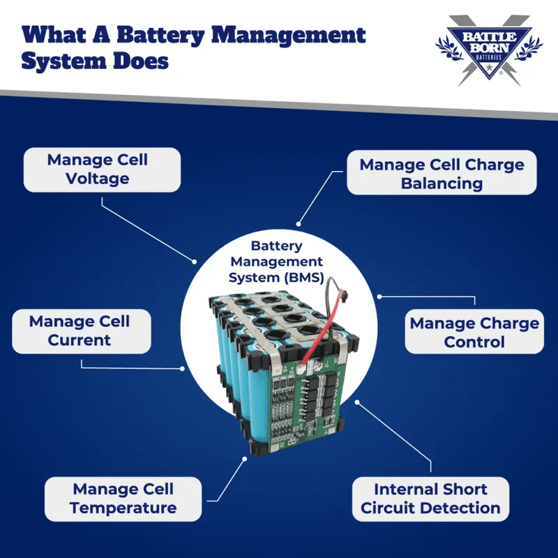
- If it detects any unsafe conditions, the BMS shuts the battery down to protect the lithium-ion cells and the user. The BMS also monitors the remaining charge in the battery.
- Therfore,the BMS component of the battery pack is essential, and each module in the battery pack requires a dedicated BMS to monitor and protect the cell set. Therefore, BMS needs to be given enough space in the battery module design and connections are made with BMS to perform the required functions.
BTMS (Battery Thermal MAnagement System)
- For battery thermal modelling, a reliable thermal model of the battery is required. Starting from the heat generated from the battery, the thermal management system can be modelled by applying the correct boundary conditions. Battery thermal models are realized by considering the electrical/electrochemical characteristics and the thermal behaviour of the battery. Heat generation inside the batteries is governed by complex electrochemical reactions depending on temperature and state of the battery. Coupled, uncoupled or partially coupled models of the battery can be realized.
- There enough gap between the cells in our design to implement thermal strips or fins.
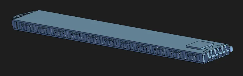
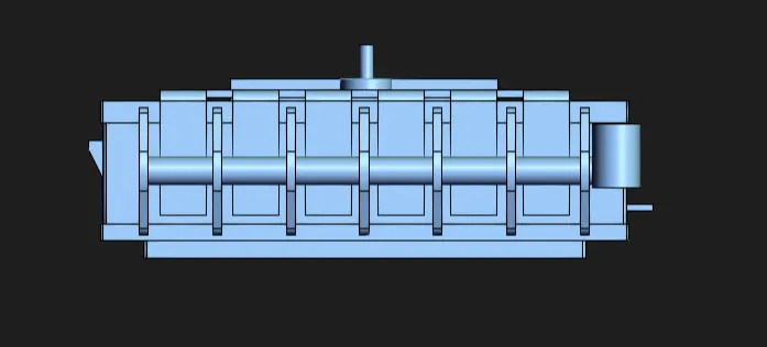
Battery Pack Enclosure
- Lithinum-ion Battery pack which is comprised of assembly of battery modules is the main source of power transmission for electric vehicles. During the actual operation of electric vehicle, the battery packs and its enclosure is subjected to harsh environmental conditions such as the external vibrations and shocks due to varying road slopes. This will result in stresses and deformations of different degrees.
- The vehicle safety heavily depends on the safety of battery pack which in turn is dependent on its mechanical features, such as the ability to resist deformation and vibration shocks. In addition, lighter weight vehicle is preferred because it can increase the range of vehicle and the life cycle of a battery pack.
- Enclosure must be design in a manner with lot of structural analysis and lot of optimisation processes.
- A wall thickness of 3 mm, which requires a gap of 1.5 mm, is recommended as the battery compartment is flush with the wall surface. Adjust the required gap or screw length for larger wall thickness.

Identification
- The pack design must incorporate some form of identification to indicate the manufacturer's name, the cell chemistry, the voltage and the capacity as well as the country of manufacture. Most manufacturers will also include a date stamp and or serial number to assist traceability in case of problems. This information is usually provided on a label but it may also be printed directly on to the battery casing.
Module Configuration in Battery Pack = 13 x 6
Length of module = 198.66mm + BMS (PCB) = 200mm
Battery Pack Length = 13* 200mm = 3600mm + 2*(3+1.5) = 3610mm = 3.61 m
Battery Pack Width = 6* 114 = 684mm + 2*(3+1.5) = 695mm = 0.695m
Battery Pack Height = 70mm + 2*(3+1.5) = 80mm = 0.08m
Conclusion
From the single-cell technical data sheet, I have designed a battery pack here for the electric vehicle with a total power of 18 kWh. The total number of cells in the 91S / 24P configuration is 2184cells. And, the nominal voltage from the 91 series connection of the battery is 300V, and the capacity we get from the configuration of 24 parallel cells is 60 Ah. The vehicle uses all the design to achieve a range of 200 km, which is an assumption to calculate the battery pack. The entire battery pack is divided into 78 modules, of which there are 28 cells in each block, and this configuration is designed to accommodate the 915 / 24P cell configuration.
Reference