Fender Design
FENDER :
Fender is the American English term for the part of an automobile, motorcycle or other vehicle body that frames a wheel well (the fender underside). Its primary purpose is to prevent sand, mud, rocks, liquids, and other road spray from being thrown into the air by the rotating tire. Fenders are typically rigid and can be damaged by contact with the road surface.
There are two types of fenders , they are
1) full bumper type
2) half bumber type
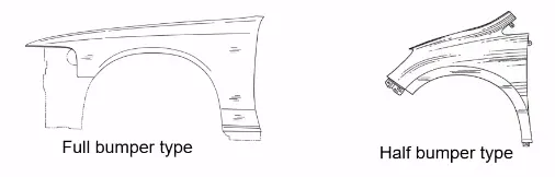
- Presently we are using the half bumper type , the reason for choosing the half bumper type is that when we choose the full bumper type the blank used for creating it is very large and also has the lot of wastage , but in the case of the half bumper type we have the possibility to reduce the scrap . This is what we called as scrap management
- In half bumper type we reduce the usage of the steel material and uses the lots of plastic on the bumper which in term decreases the cars weight and increases the performance
Manufacturing process
The manufacturing of the fender majorly involves these operations.
1.Embossing
2.Bending
3.Cutting and Blanking
Embossing
Embossing is a metal forming process for producing raised or sunken designs or relief in sheet material using matched male and female roller dies, theoretically with no change in metal thickness, or by passing sheet or a strip of metal between rolls of the desired pattern.
Bending
Metal bending is a process by which metal can be deformed when applying force to the subject, which causes it to bend at an angle and form the anticipated shape, which often results in it being in a ‘V’ or a ‘U’ shape. This is done through the application of force on a workpiece. The force on the work piece can be mechanical, pneumatic or hydraulic.
Cutting and Blanking
Cutting processes are those in which a piece of sheet metal is separated by applying a great enough shearing force to cause the material to fail.
Blanking is a steel manufacturing process in which a flat, geometric shape is created by feeding a coil of sheet metal into a press and die. In this process, the blank is punched out from the large metal sheet.
MOUNTING REGIONS ON FENDER :

There are 5 mounting regions on the fender , they are
- A- pillar mounting
- Body mounting
- Sill mounting
- Bumper mounting
- Drip mounting
GIVEN DATA :
DESIGN 0F DRIP AREA MOUNTING :
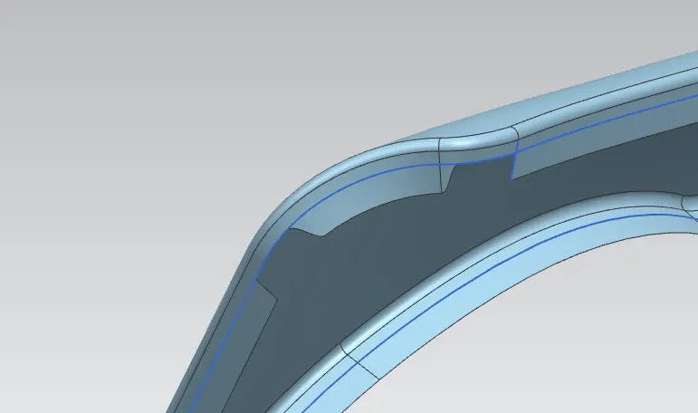
From the given data Drip area we have to initially leave 200-300 mm for cowl top and have to leave at least 150 mm at the front .
For that firstly we have to create the a piller flange from we have to leave the 200mm.

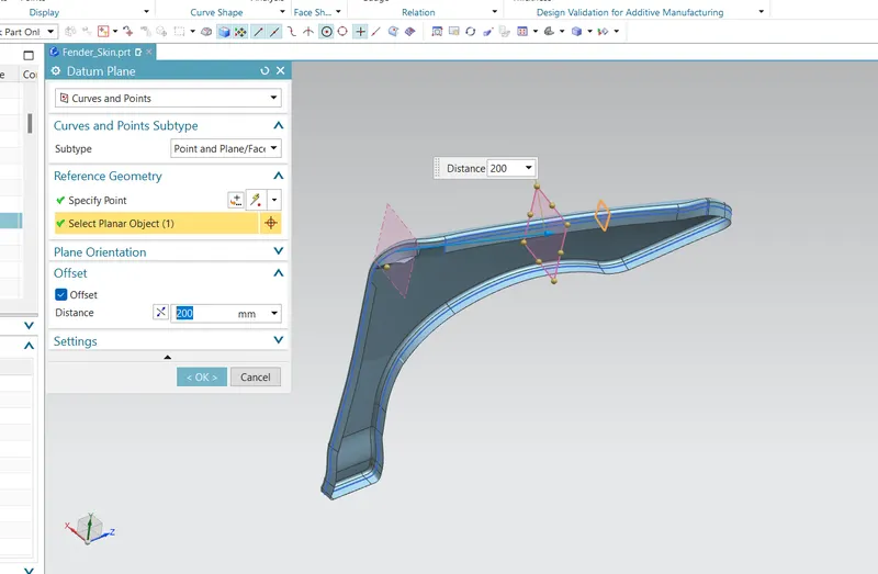
Now i create a datum of 200 mm and create a another datum plane of 150 mm from the other side.
next by intresetin curve command make intersection to datum and sheet so we get required legnth of flange as given in the master section.
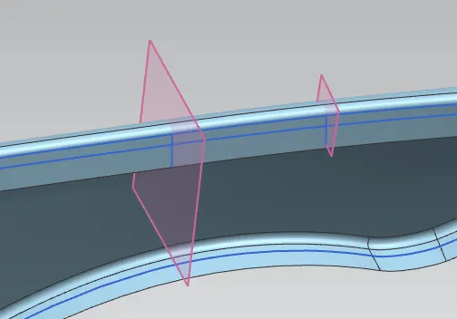
now trim the sheet.
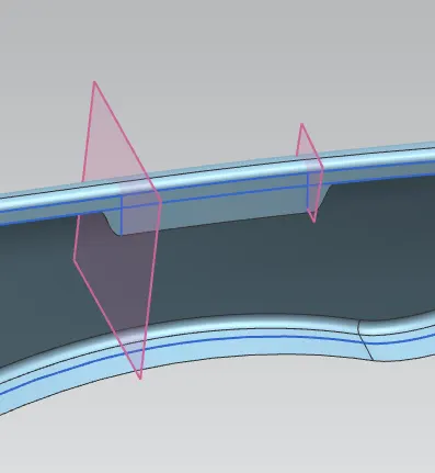
By useing law extension created the drip area by following the master section dimensions.
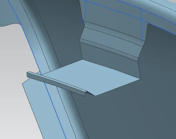
here the legnth of the flange is long for stiffiness of the sheet i create a drat.
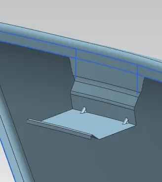
Now i create a sketch to emboss.
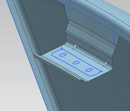
create a emboss.
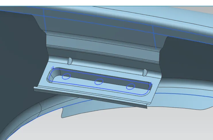
After that i gave all the fillets to avoid the sharp corners.
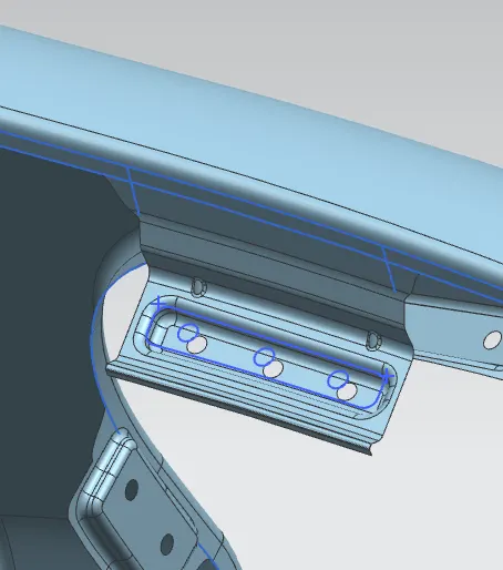
So the my drip area is created as for the give master section.
DESIGN OF A-PILLAR MOUNTING AREA :
For this there is not master section is provied so that i create the A piller mounting mounting by geberal design codserdations.
- Firstly i used law if extenstion to extent the sheet and trin corner by create curve.
- After create a skecth and make emboss
- Gave fillets to avoid the all the sharp corner with maximum radius without over laping the falnges.
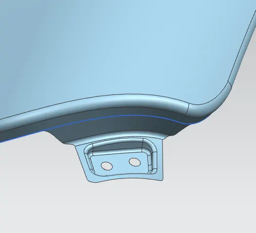
DESIGN OF SILL MOUNTING AREA :
- Firstly i used extent the sheet and trim corner by create curve.
- After create a skecth and make emboss
- Gave fillets to avoid the all the sharp corner with maximum radius without over laping the falnges.
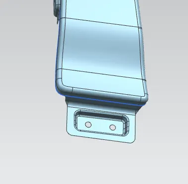
DESIGN OF BUMPER MOUNTING AREA :
- Firstly i used law if extenstion to extent the sheet and trin corner by create curve.
- After create a skecth and make emboss
- Gave fillets to avoid the all the sharp corner with maximum radius without over laping the falnges.
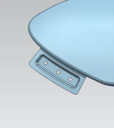
DESIGN OF BODY MOUNTING AREA :
- Firstly i used extent the sheet and trim corner by create curve.
- After create a skecth and make emboss
- Gave fillets to avoid the all the sharp corner with maximum radius without over laping the falnges.
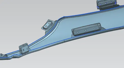
After creating all the flange thicken to 0.75mm.
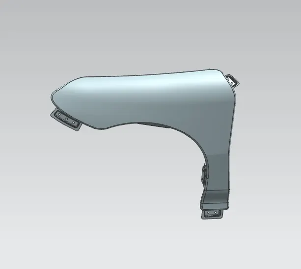
Finally my fender is completed.