Advanced Sheet Metal Design Using NX Cad Challenge_1_Casing Design
1.Title of the Project
MODELLING OF SHEET METAL CASING
2.Objective
Design a sheet metal casing using Siemens NX Sheetmetal application.
3.Introduction
The sheet metal application provides an environment for the design of sheet metal parts used in machinery, automotive and aerospace application etc. Enclosures, brackets and other parts normally manufactured with a brake press. Through this project we are able to design a sheet metal casing using the digital CAD tool (Siemens NX 12).
4.Design methodology / approach (To be explained with the help of Flowcharts only)
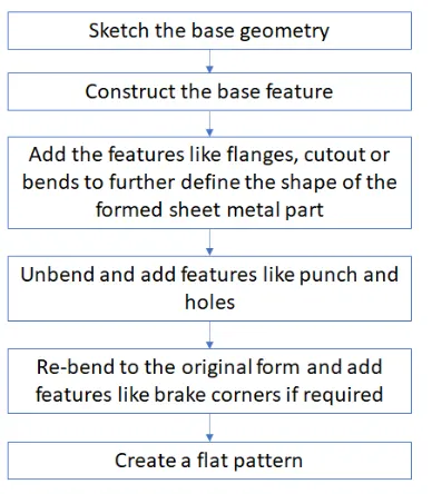
5.Description (Need to explain tools/ Features used while designing)
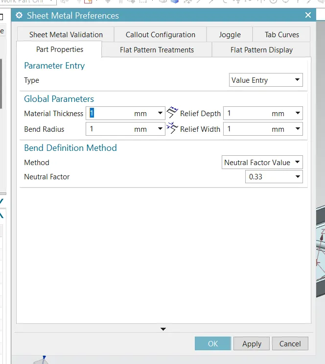
Create new file of sheet metal model
Then set the Sheet metal preference to 1mm
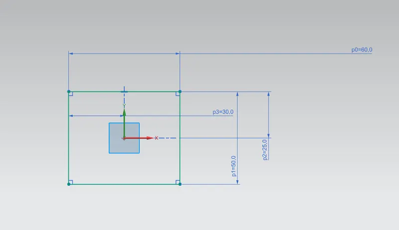
First we have create the sketch to create the tab
select sketch option adn define axis and draw the rectangle of 60X50 Dimensions and finish the sketch.
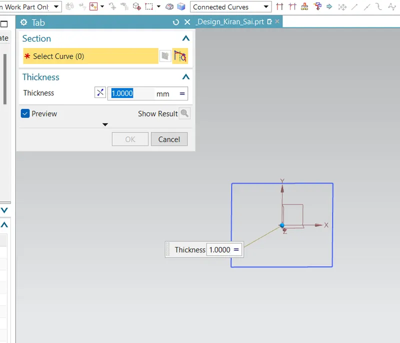
Now we will choose the tab command and select the sketch and define the thickness 1.0 mm
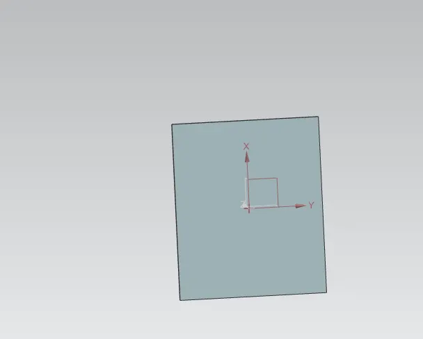
Now i will created a another sketch on XY axis
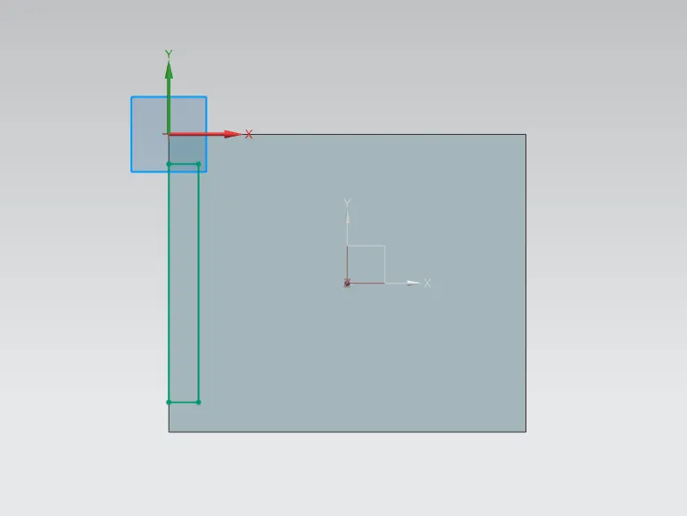
then i use normal cutout command to cut the sheet according to the sketch.
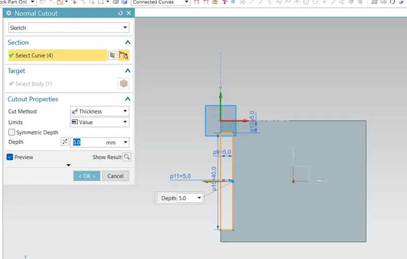
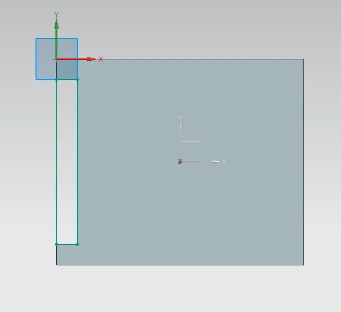
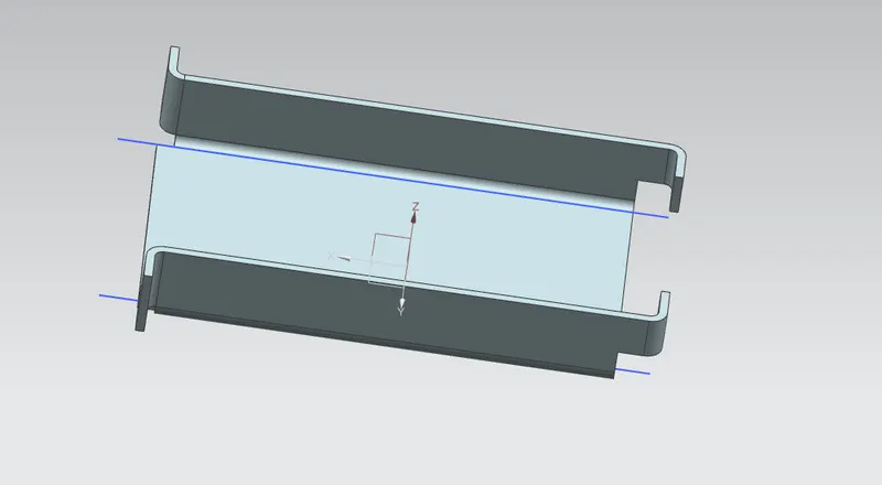
Then i used another sketch to use the bend command
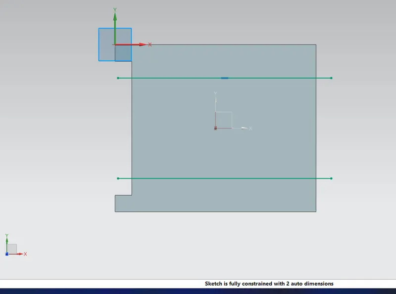
Then bend the sheet according to sketch
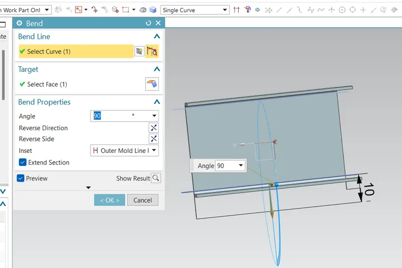
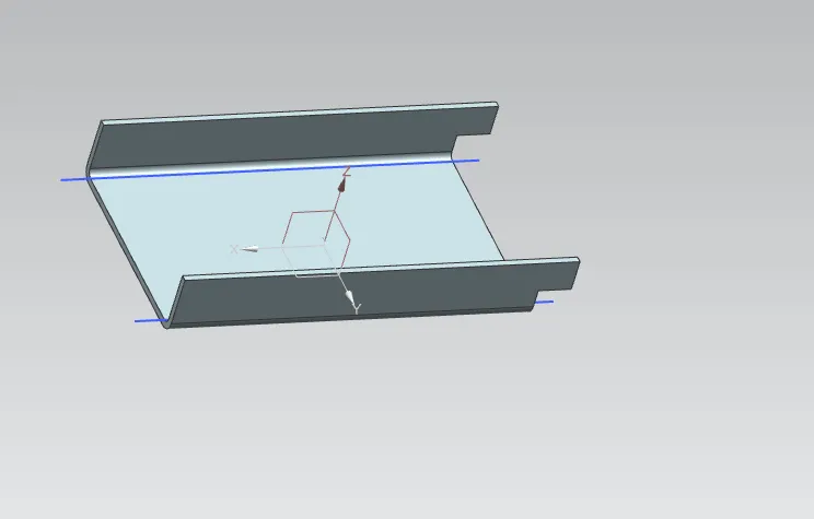
create the flane on the other side by using the same flange command.
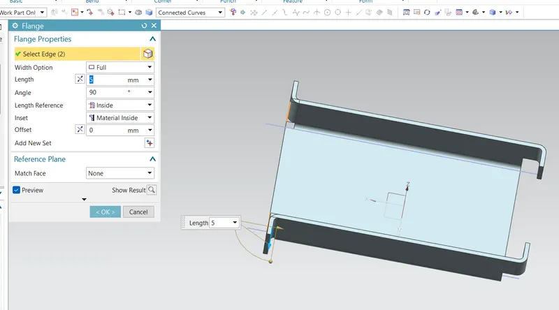
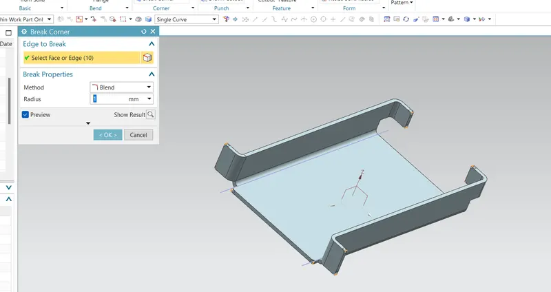
Filet the sharp corner by usin g the break out cirner command.
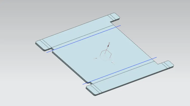
Unbend the feature by using ṭhe unbendcommand.
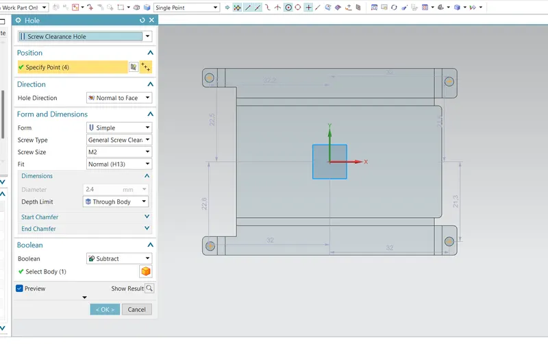
Create the sketch for the hole make points
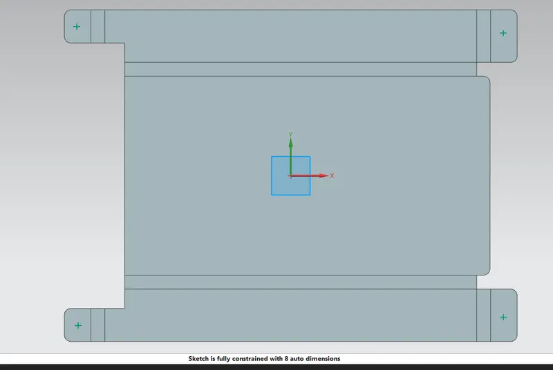
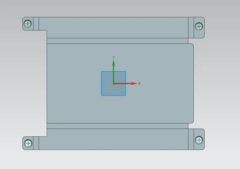
Using the hole command make four hole by selecting the point and parameters as shown in below image
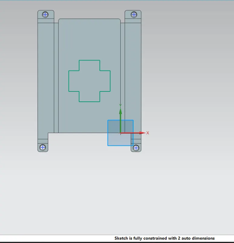
Draw the sketch for the emboss
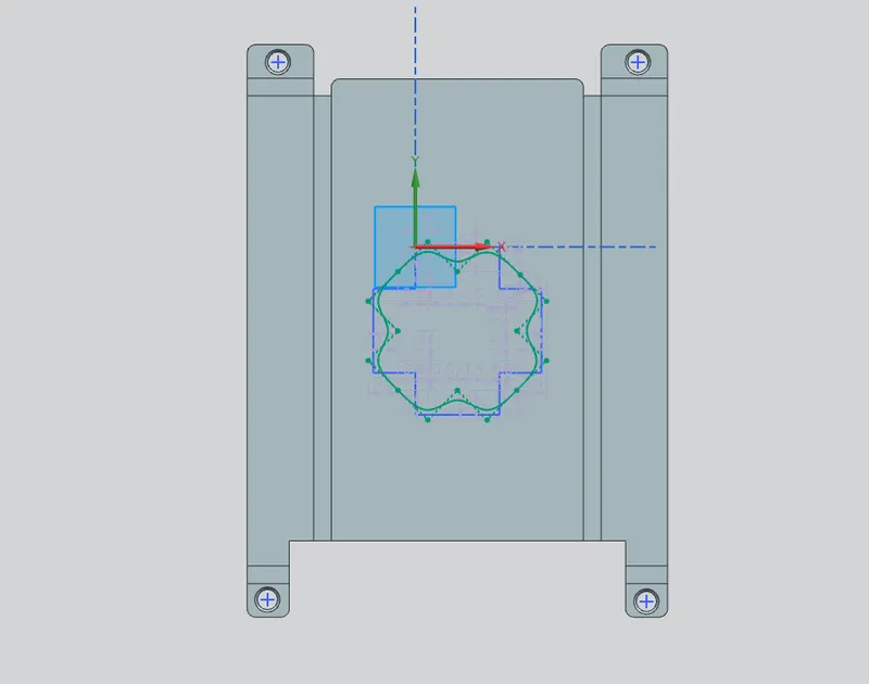
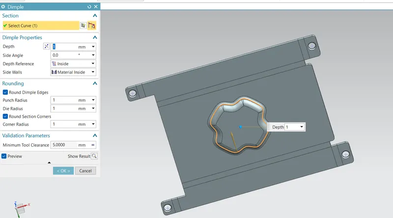
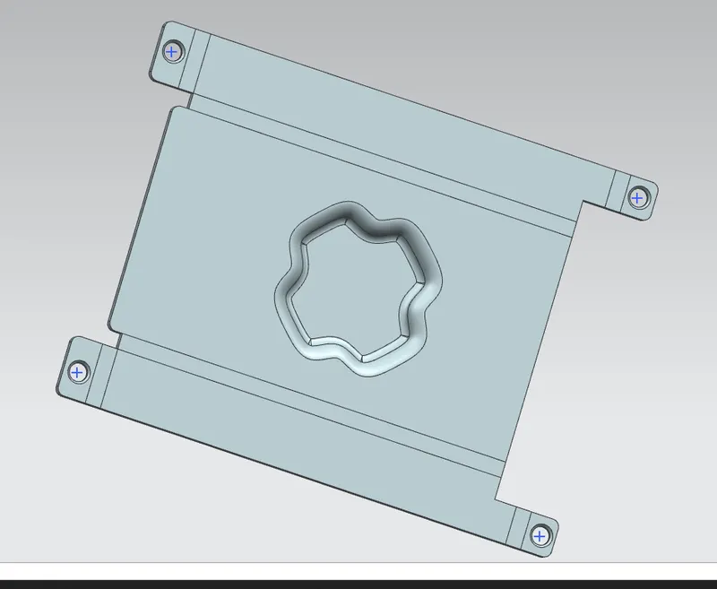
Add dimpel for the emboss
Dimple in the sheet metal component provides more strength and rigidity to the flat structure of the component. Dimple features is created using the sketch created in any face or any flange in the sheet metal components.
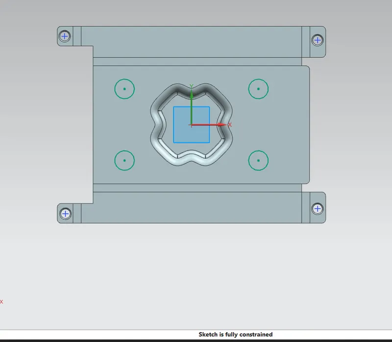
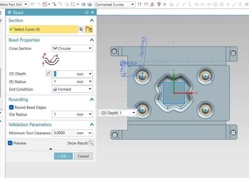
Create another sketch for bead operation with diameter 5mm
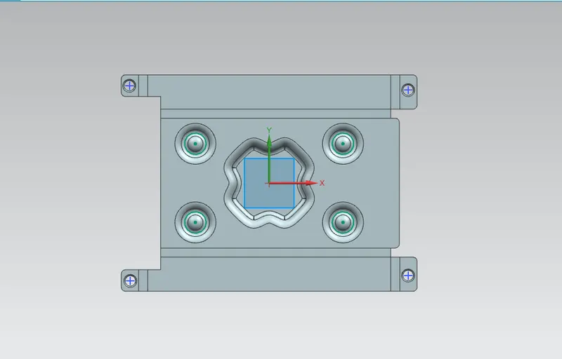
Then rebend
All feature added after the unbend feature are added in the unbend state itself. After the addition of sketches and additional features are completed, the sheet metal components has to be re bend to the required position.
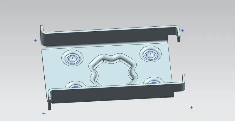
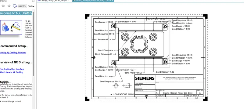
then do flat pattern and create the drafting
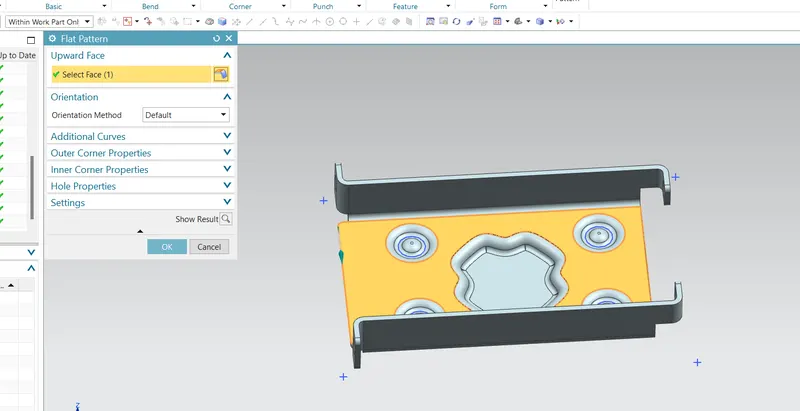
Flat pattern is the representation of the entire sheet metal component in the 2D form of the flat sheet metal with all the additional feature in the form of lines or edges. It removes the possible errors such as interference or collision with in the same component.
After the design is complete, the execution or the manufacturing of the component requires a technical drawing of the component with the provided scale and with accuracy
6.Upload a min of four screenshots of Model in the report. (Front View, Side View, Isometric View and the Top View)
Front View
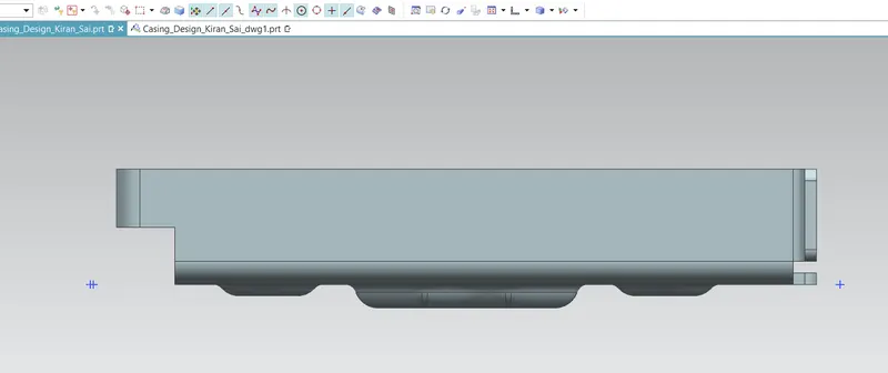
Side View
Right side
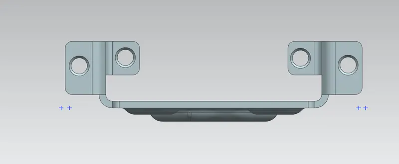
Left Side
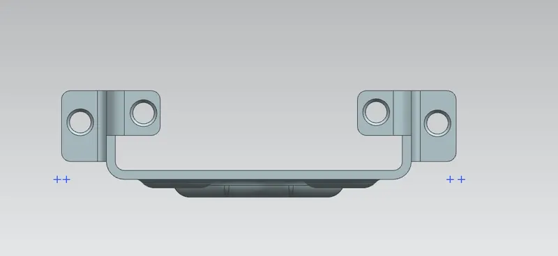
Isometric View
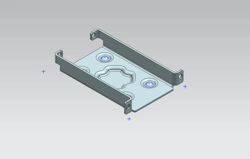
Top View
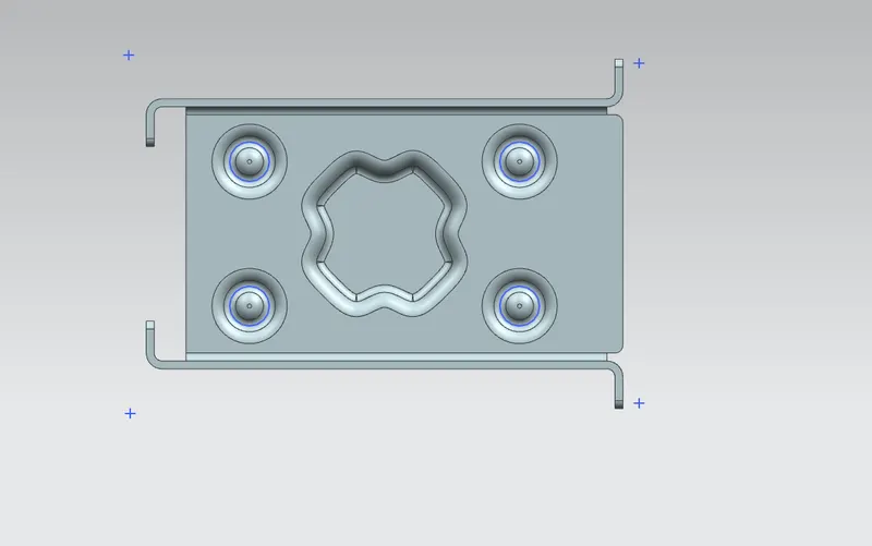
7.Attach Detailed Drawing Sheet Image
Open new sheeet of drawing and select the flatpattern
8.Conclusion
Finally the modelling of the sheet metal casing using NX CAD has successfully completed and though this project I can able to know the various GUI of NX and different comments and tool use in various sheet metal modelling.