Week - 4
Q1. To implement the control logic of a washing machine using stateflow in simlink
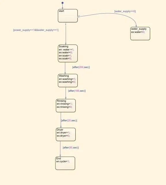
- If power supplyis available,the syatem is activited
- If the water supply is not available,stop the process& indicate throught the LED
- Soaking time happens for next 20s & dryer runs 50s
Afer all the process have completed turn on the finished LED
The model contains following attachments
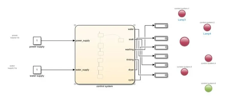
Chart Diagram:
Parameters:
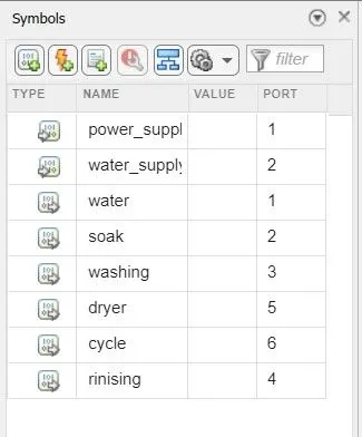
Here we are giving water ,soak, washing, rinsing ,dryer ,cycle and sufficient time to solve the parameters. And also we are gving water_supply and power_supply as input of the chart
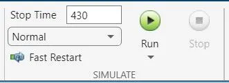
Simultion time parametres:
Output:
Condition 1
When we not provide water supply and check output
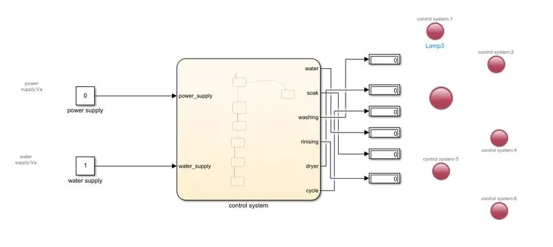
Fropm thr above block diagram we can see that indicator of water is showing is red i.e when there is no water supply the process is terminated and red LEd indicator is use to indicate state
Condition 2
When water supply is on
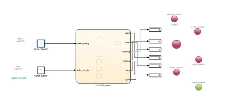
As we observe that from above figure all the states have been executed and indicating the process completion done and the indicator showing the green
conclusion
The simulation of the Washing machine using state floe is done and the result is staisfactory.
*****************************************************
Q2. Simulate the gear shift logic by simlink .
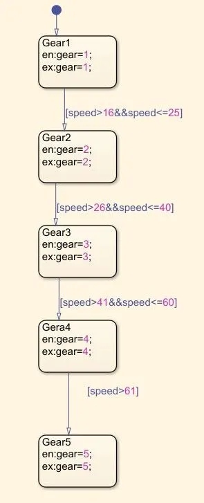
Making a simlink chart to the gear shift for the menstioned parameters
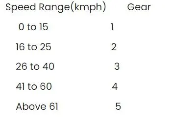
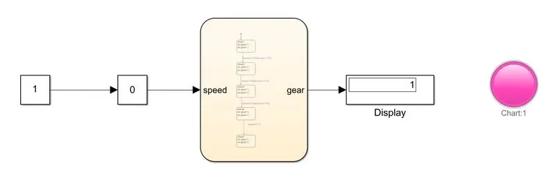
Chat diagram:
Parametrs:
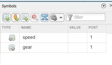
Here we give speed as input for the chart and speed is the ouput for the chart
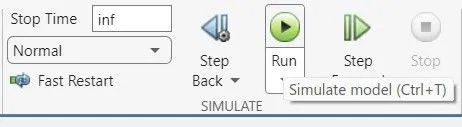
Simulation Time parameter:
Here are gave time as inf for our simulation should run untill we stop it
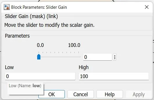
Input
we use Slidergain to provide input the chat
output
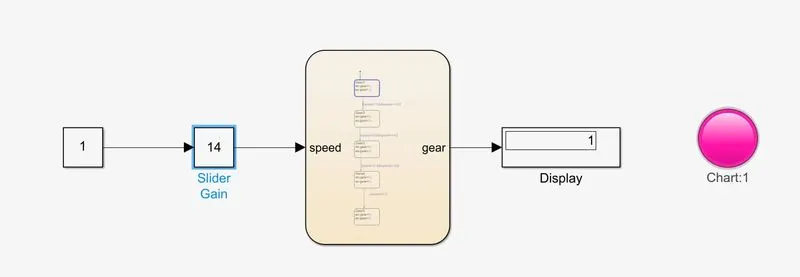
Gear:1
Speed range 0 to 15 Kmph
Input speed :10kmph
color :pink
Gear :2
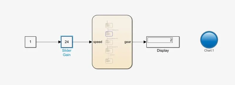
Speed range 16 to 25 Kmph
Input speed :20kmph
color :blue
Gear :3
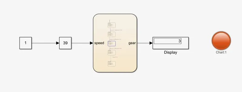
Speed range 26 to 40 Kmph
Input speed :30kmph
color :orange
Gear :4
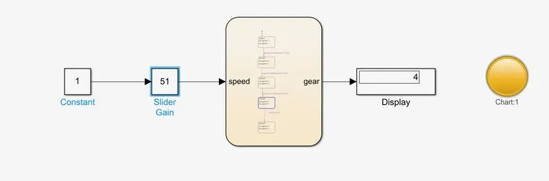
Speed range 41 to 60 Kmph
Input speed :50kmph
color :yellow
Gear 5
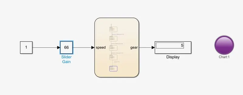
Speed range: above60 Kmph
Input speed :80kmph
color :violet
Conclusion
gear box state flow is crated by using simlink and results satisfactory.