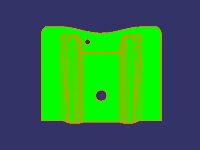
Week 8 - Challenge 1 - Base Bracket Design
Class A surface:
It is input surface.
It is the visible aesthetic surface which have curvature and tangency alignment to ideal aesthetical reflection quality of any automotive component. Class A surface refers to those surfaces which are visible It is a required where aesthetics has a significant contribution.
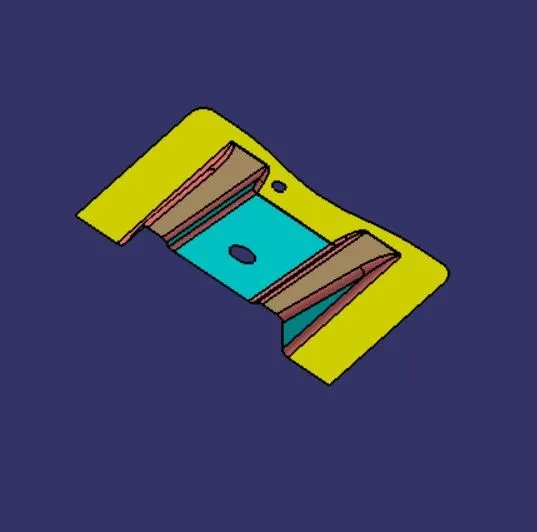
Class B surface:
It is a surface which is offset below a certain thickness from the class A surface. All the features of the product are to be performed on the class B surface with respect to class A surface
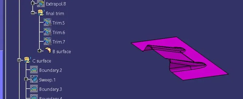
Class C surface:
class c surface is the surface which is used to join both the Class A and Class B. This surface connects both A and B surfaces along the Tooling Axis. It contains the draft as per the design. It is basically the thickened surface between both A and B surface
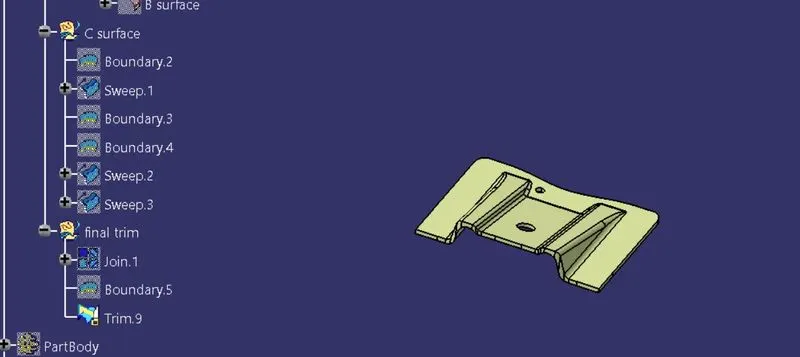
- Screenshots of the Draft analysis report for both the given Class-A surface and the final plastic component
- Image of the complete Draft analysis
DRAFTING ANALYSIS:
The Draft Analysis command enables you to detect if the part you drafted will be easily removed. This type of analysis is performed based on color ranges identifying zones on the analyzed element where the deviation from the draft direction at any point, corresponds to specified values.
class A Surface Draft Analysis
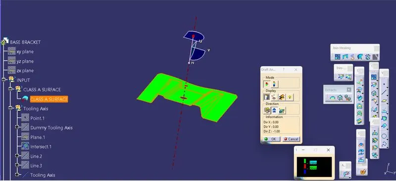
The Above Draft Analysis is done after Creating the Tooling axis.
To Create the Tooling Axis
- Firstly create the dummy axis and intersection on the base bracket.
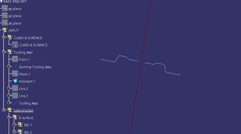
- Now create lines through the walls of a base bracket using point to point option with the help of intersect 1 where you think the tooling might create problem. And using these 2 lines create a bisecting line from reference point in Z direction. This will form a main tooling axis in Z direction
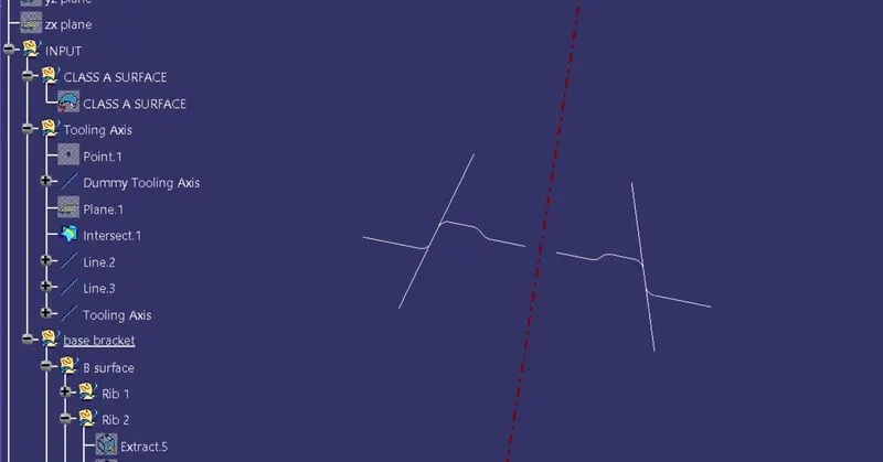
- After Creating the Tooling AXis Draft analysis is done on class A Surface.
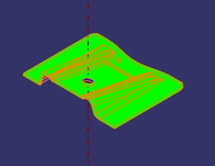
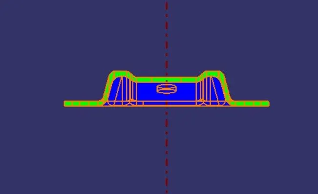
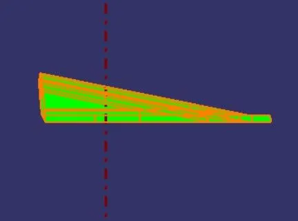
- The green colour in this analysis shows that our model is passed in the analysis.And Maximun Draft Analysis 3 degree.
- Red color indicates the angle 0 degree draft angle.
- and blue color indicates the negative draft angle
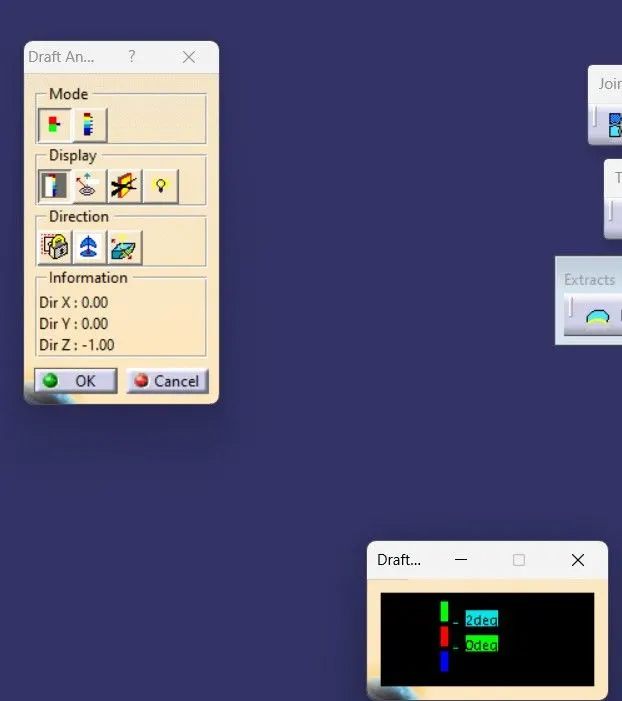
Class B surface Creation:
- After completation of Class A draft ananlysis
- Now we are going create the class B surface by taking class A surface as input data.
- Now extract Ribs from the Class A surface and do untrim and Explotation to the surface and trim the surface for required output and offset the surface to 2.5mm .
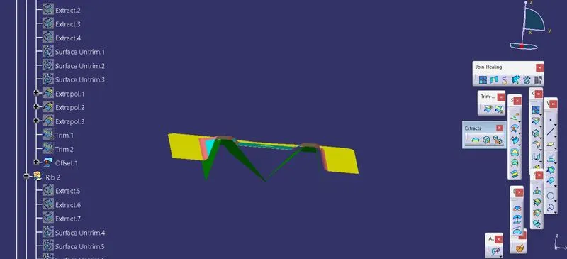
- As the same we have to create base
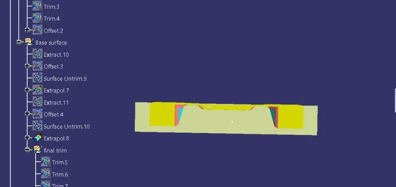
- After extracting all the surfaces we will done final trim of the offset surface .
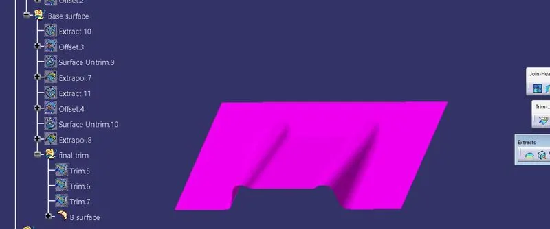
- Now the class B surface is created and check if it fully closed or not but using boundray command.
Class C surface
- Now we have boh class A and B surface .
- Firstly create a boundry by using class A surface.
- And using sweep command create the Class C surface.
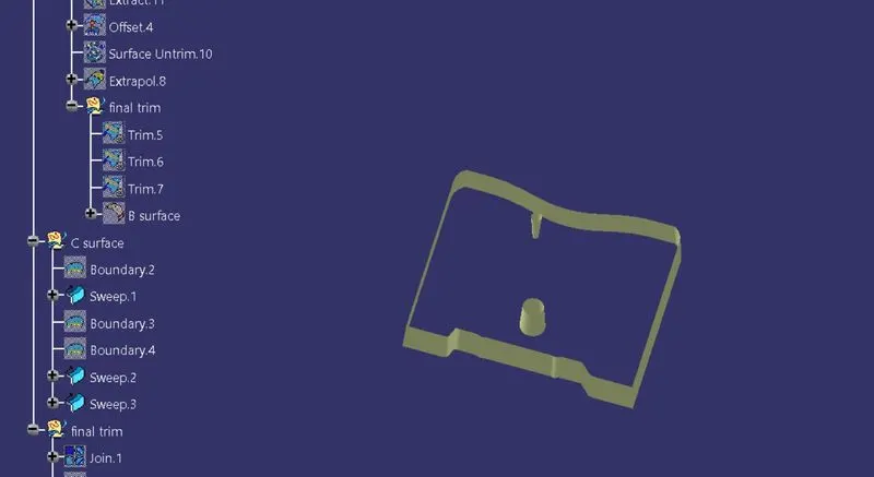
- BY Class A and Class C join together
- Now we trim wit both A+c +B
- Now we check the if it is fully closed surface or not by using boundry command.
- If it is fully closed Switch to part drawing and used close surface crete the close surface.
Part Body
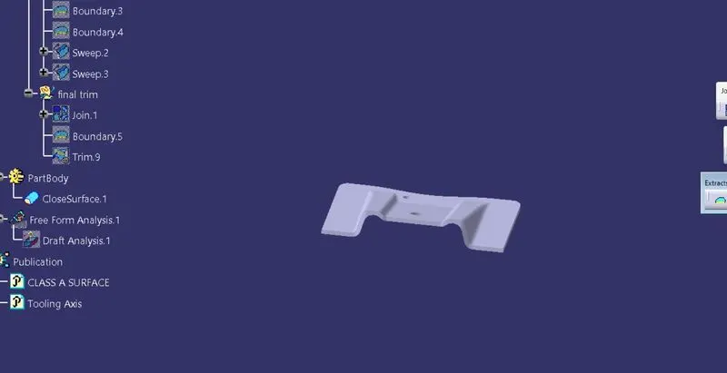
- Screenshots of the solid model with the proper color code of the draft angle in various orientations (Isometric, Front, Side, and Top View)
Isometric View
Front View
Side View
Top View