Wiring harness routing & packaging Rules Week 3 Challenge
Q1. Download following cad data & define it as Electrical support using Electrical Part design Workbench. Define all the necessary properties.
Note: if you face any issue with point definition, point selection, Right-click on the point definition window and use the reset option.
- Download the P clamp from the above link as .stp file abnd save as .CATPart file.
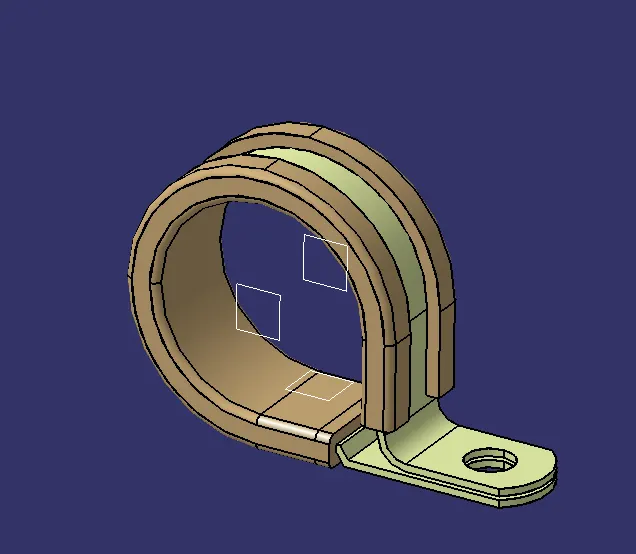
- Now we have to define the geometry parameters.
- In order to define the geometry parameters, we need to navigate to the Part Workbench.
- Then we need to create points and plains at the entry and exit points.
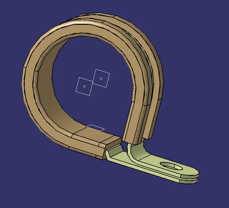
- Now in order to define the P-Clamp as a Electrical support we have to navigate to the Electrical Part design Workbench.
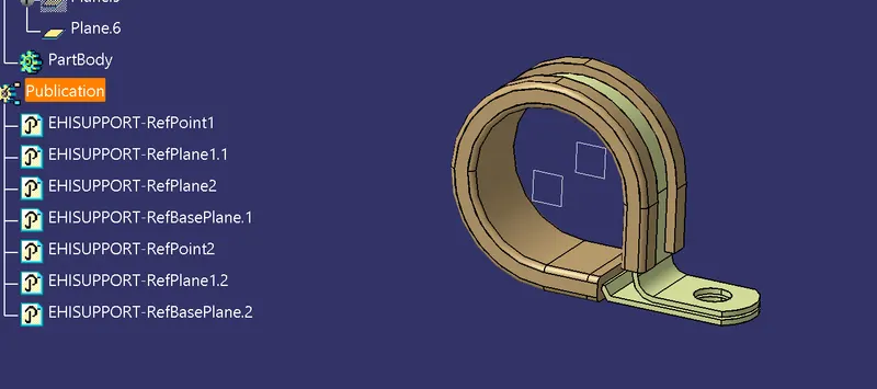
- Now using the 'Define support part' option we can define the P-Clamp Entry and Exit points.
- As the P-Clamp is Bi-directional so we need to define the support two times.
Q2. Download following Back shell cad data & define it as Electrical back shell using Electrical Part design Workbench. Define all the necessary properties.
Tyco 1738312-1 https://www.te.com/usa-en/product-1738312-1.html
- A backshell is an accessory that mounts to the rear threads of a connector to enhance its operational characteristics. The primary function of a backshell is to provide strain relief, which minimizes stress from the cable, on the junction where the wires terminate to the contacts.
- Backshells come in a variety of finishes, materials, and angle configurations. For material compatibility and aesthetics, backshells and connectors should have a matching material and finish. And to provide simple cable management, most backshells may be ordered in 45º and 90º angles.
- Download the P clamp from the above link as .stp file abnd save as .CATPart file.
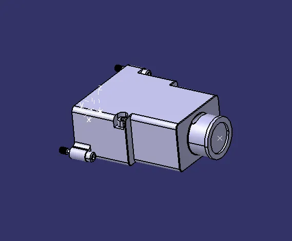
- Identify from which side the bundle will enter and the side which will mate with the connector.
- Create mid-point at the bundle entry side
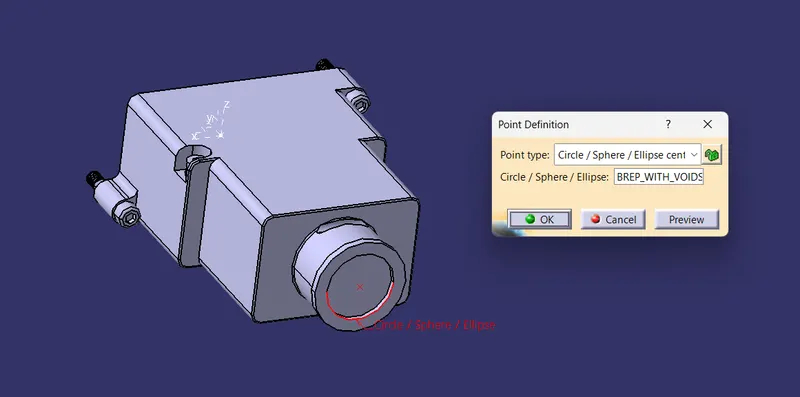
- Connector mating side:
- Create mid-point at the connector mating side.
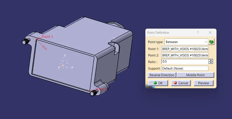
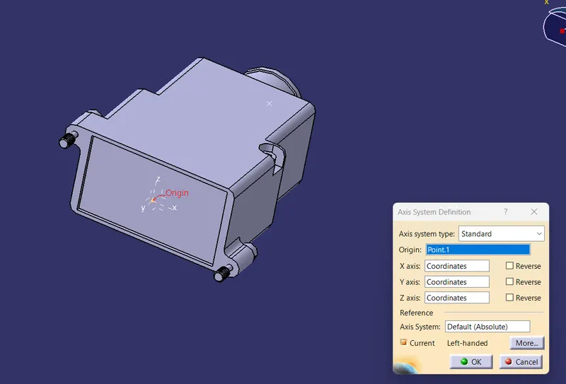
- Create an Axis system at the Connector mating side.
- The axis system should be created at the center of the mating surface.
- The axis must be defined as defined for the connectors show that it will connect easily.
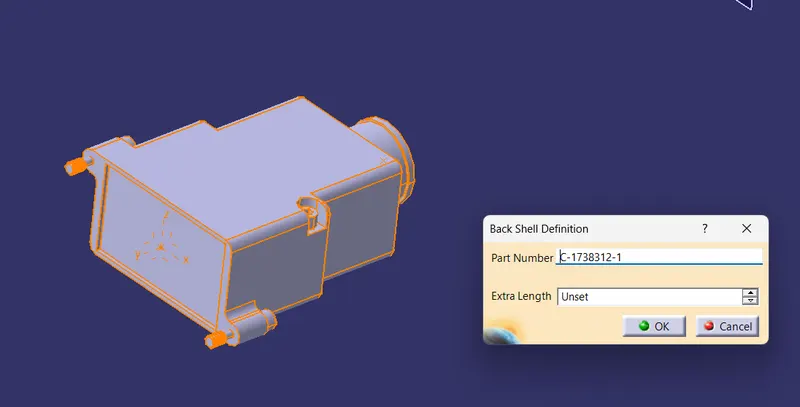
- To define the Electrical properties, we need to navigate to the Electrical Part design workbench.
- There we need to define the component as the 'Backshell'.
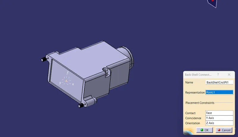
- Define the Backshell connection point.
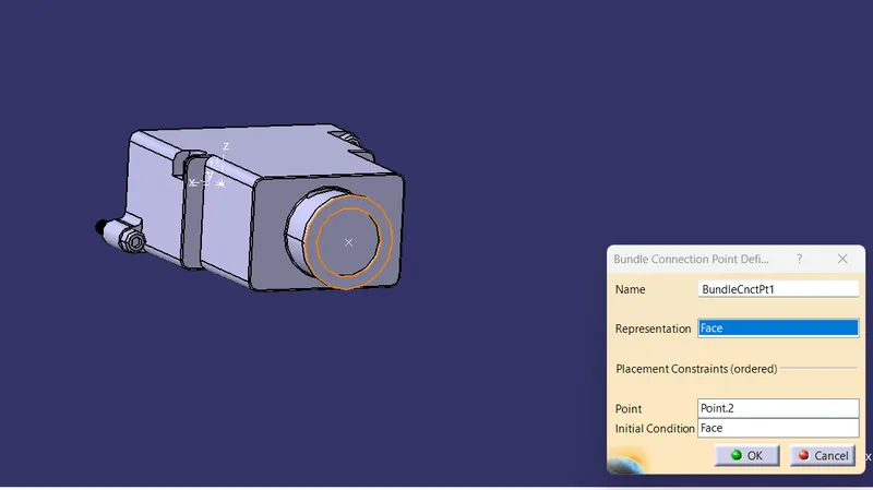
- Then define the Bundle connection point.
Q3. Create Following Corrugated tubes & Add them in Catalogue under “Slit COT” family.
|
Name |
ID (mm) |
OD (mm) |
Thickness (mm) |
|
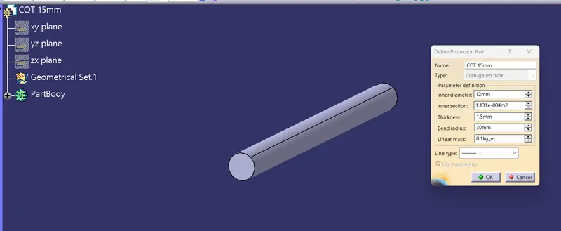
15mm COT |
12 |
15 |
1.5 |
|
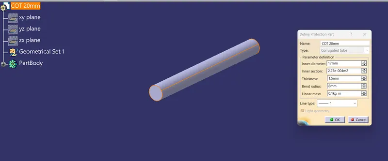
20mm COT |
17 |
20 |
1.5 |
|
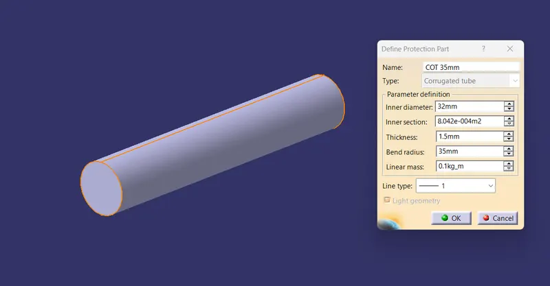
35mm COT |
32 |
35 |
1.5 |
|
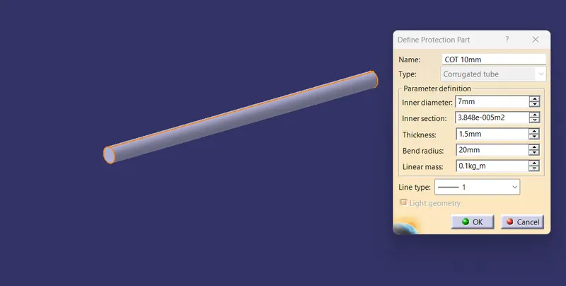
10mm COT |
7 |
10 |
1.5 |
|
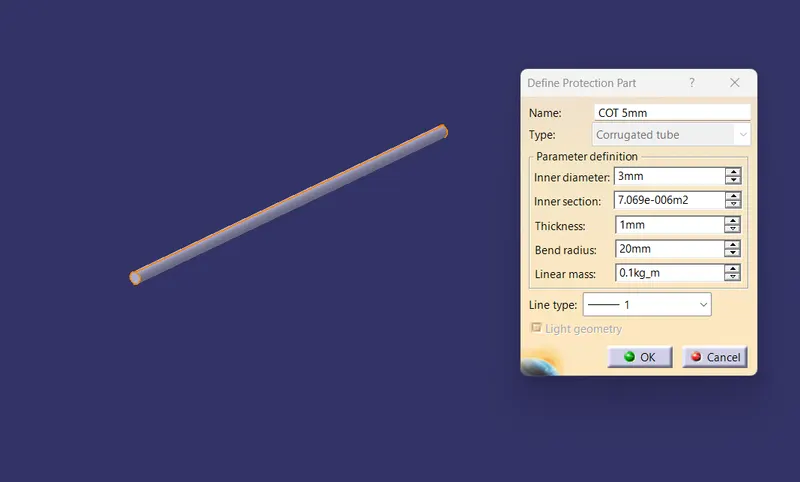
5mm COT |
3 |
5 |
1 |
- Create a Catalogue document and adding Slit COT as a family and saving the document in our desired folder.
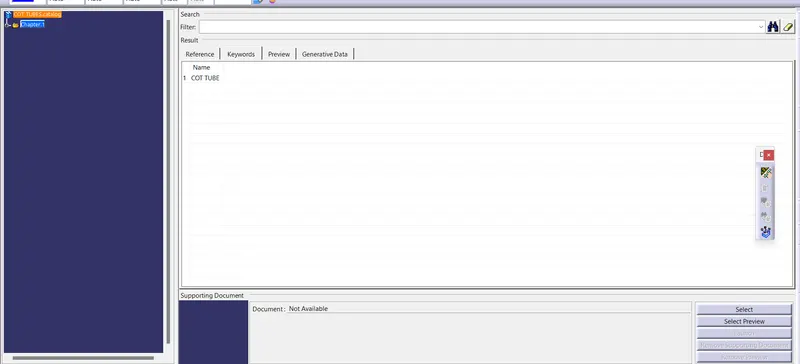
- Creating the following corrugated tubes as per the dimensions given in the table and storing in the Slit COT family catalogue document.
1. 15 mm COT TUBE:
2. 20 mm COT TUBE:
3. 35 mm COT TUBE:
4. 10 mm COT TUBE:
5. 5 mm COT TUBE:
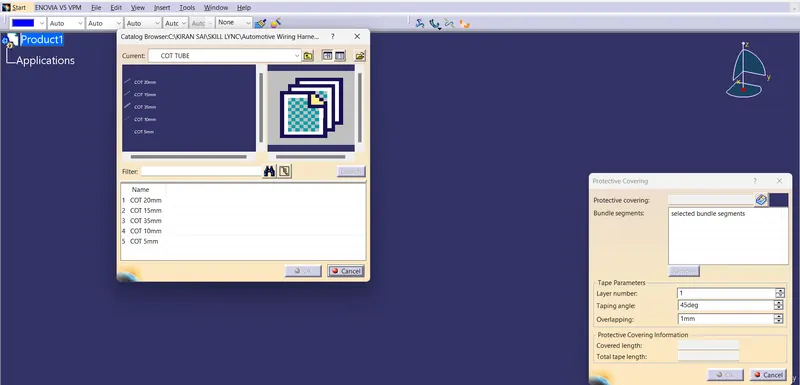
CORRUGATED TUBE CATALOGUE: