Roof Design
Introduction:
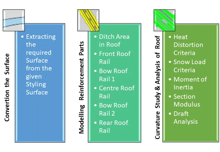
An automobile roof is the portion of an automobile that sits above the passenger compartment, protecting the vehicle occupants from sun, wind, rain, and other external elements. Under the styling surface that is seen from the outside, many other structures under the roof contribute to its strength and stability. The number of such reinforcement structures/supports differs concerning the size of the vehicle. They are primarily installed on flatter areas of the roof to enhance strength.
These are the Front Roof Rail, Rear Roof Rail, Centre Roof Rail, and Bow Roof Design which are given Mastics and spot-welded to roof flanges & ditch areas and improve NVH value by increasing the strength of the roof using mastic sealants.
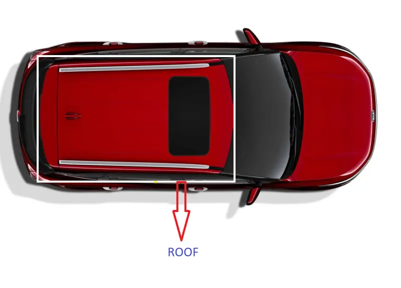
WHY REINFORCEMENTS :
If the roof is flat it is very weak and cannot able to with stand the forces like snow , so in order to increase the strength of the roof these reinforcements like front roof rail, central roof rail, rear roof rail and the bow roofs are introduced and joined to the flat surface of the roof with the different joining process
Types of Automobile Roofs:
- Convertible: A convertible, cabriolet, or spyder is a passenger car that can be driven with or without a roof in place.
- Hardtop: A hardtop is a rigid form of automobile roof, which for modern cars is typically constructed from metal. A hardtop roof can be either fixed, detachable for separate storage, or retractable within the vehicle itself.
- Sunroof: An Automotive sunroof is a movable panel that is operable to uncover a window in an automobile roof.which allows light and fresh air into the passenger compartment.
- T-top: A T-top is an automobile roof with a removable panel on each side of a rigid bar running from the center of one structural bar between pillars to the center of the next structural bar. The panels of a traditional T-top are usually made of auto-grade safety glass.
- Targa Top: Itis a semi-convertible car body style with a removable roof section and a full-width roll bar behind the seats.
- Vinyl roof: Vinyl roof refers to a vinyl conversion for an automobile’s top. This conversation was originally designed to give the appearance of a convertible to models with a fixed roof but eventually, it evolved into a styling statement in its own right.
Design consideration of Roof:
- Visibility Criteria.
- Head Clearance.
- Curvature Study.
- Heat Distortion and Snow Load Criteria.
- Draft Analysis.
- Safety Parameters.
Roof Crush Test:
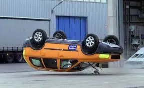
Safety point of view vehicle roof plays a very crucial role, especially in rollover kind of accidents, in which the vehicle tips over onto its side of the roof. And vehicle rollover crashes are the cause of many fatalities and head, neck, and spine trauma around the world.
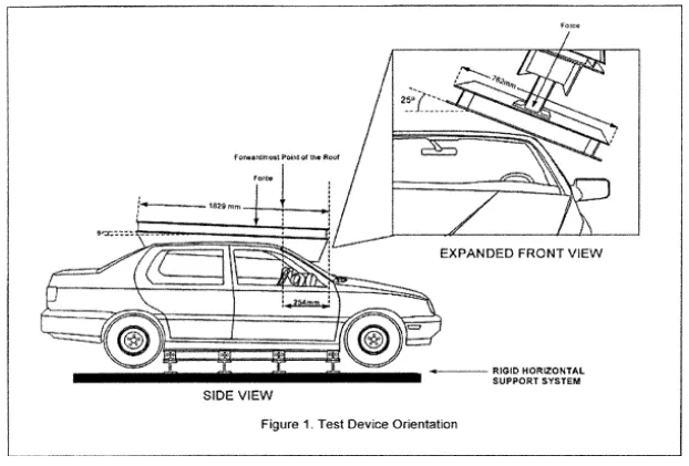
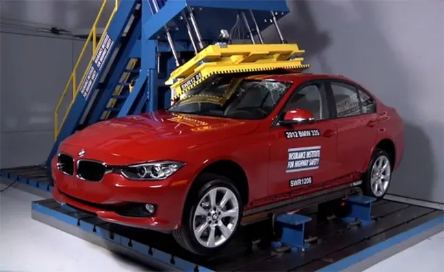
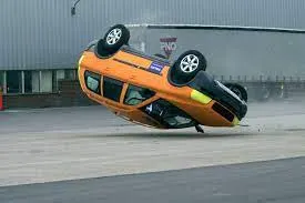
Car Rollover Test:
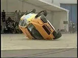
The rollover test is conducted because a rollover is a type of vehicle crash in which a vehicle tips over onto its side or roof. Rollovers have a higher fatality rate than other types of vehicle collisions.
Vehicle rollovers are divided into two categories: tripped and untripped. Tripped rollovers are caused by forces from an external object, such as a curb or a collision with another vehicle. Untripped crashes are the result of steering input, speed, and friction with the ground.
Vehicles which have a higher center of gravity like SUVs or Small Trucks are more prone to rollover. Rollover accidents typically involve a singular vehicle that loses control due to icy or snowy road conditions, soft road shoulders, uneven ground, collision with curbs or guardrails after a vehicle has lost traction, or hitting an obstacle while driving.
During a rollover accident, the regional body distribution of injuries normally affects five main areas: head and neck, thorax, abdomen, upper limbs, and lower limbs. The majority of rollover crash victims sustain multiple injuries throughout these regions with the head and neck being the most vulnerable area. Some of the most common rollover injuries include traumatic brain injury, spinal cord injury, broken bones, cuts, scrapes, and bruises. These injuries are caused by slamming into another vehicle or obstacle, impact with unsecured cargo, contact with broken glass or torn metal, or being tossed within the vehicle or ejected from the vehicle.
Manufacturing Techniques:
By outer board machining process, bar-shaped assembly, ring-shaped component processing, and roof cant rail processing technology formed respectively.
Outside plate process: the first step, open the straight snips plate: first select the applicable cold coiling specification, and cold coiling is opened flat; Then according to the production material specification, will open cold coiling after the flat and is cut into the iron plate of the corresponding size; Finally the iron plate after shear is cleaned to iron filings; The first step, oil pressure, punch press: the first iron plate is extended; Secondly to its trimming and punching; Then to its flanging and punching; Finally, after punching completes, it is carried out to the operation of side folding; Completed the making of the outside plate.
Bar-shaped assembly and ring-shaped component process: the first step, blanking, stamps out an iron plate with the outline blank of many roof cant rails, a ring-shaped component, and a bar-shaped assembly; the Second step, carries out annular punching to ring-shaped component; Bar shaped assembly and roof cant rail are carried out to bar-shaped punching.
Car roof anabolic process: the first step, is by a plurality of M6 nuts of a side spot welding of the ring-shaped component; By two M6 nuts of the bar-shaped assembly two ends spot welding; the Second step, spots weld bar shaped assembly the opposite side of the corresponding nut of the ring-shaped component; And circular groups and the punching of bar-shaped assembly are aimed at; The 3rd step, is welded to ring-shaped component the inner side of the outside plate; The 4th step, spots weld roof cant rail the inner side of the outside plate; Finally car roof integral body is carried out to sanding thorn and ending.
Now we will design a roof using a given class A surface.
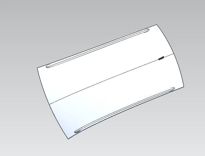
Now ectract the face from the class A surface
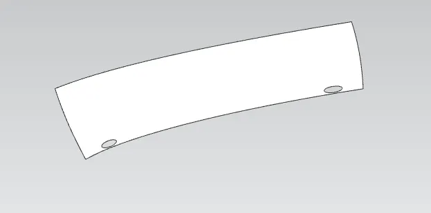
Aftre that untrim the surface.
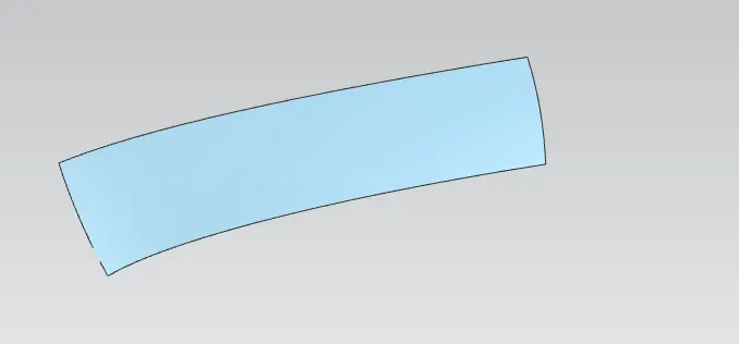
After unrim the surface we will get some large surface from the untrim surface so trim the sheet with the extract surface.
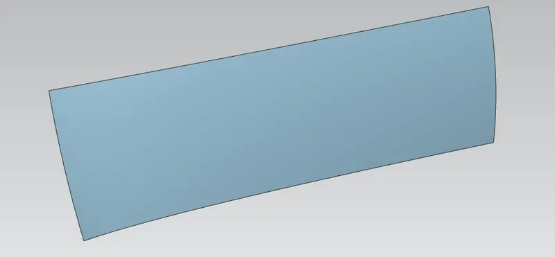
now create a bridge curve to the corner to avoid the shrap corner.
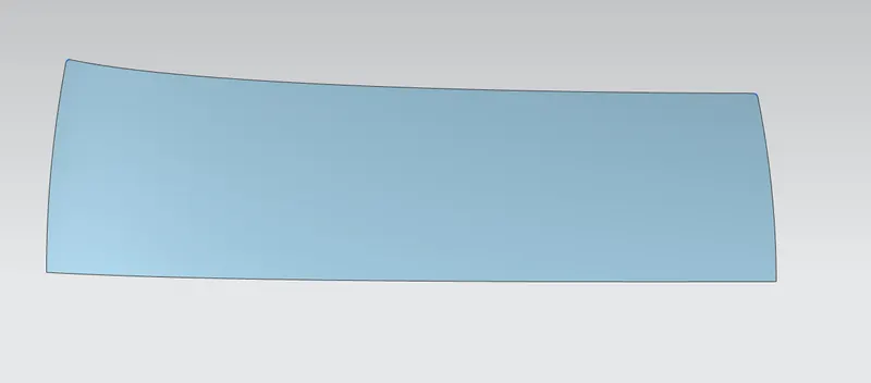
Now using the master section front roof we will follow the standards.
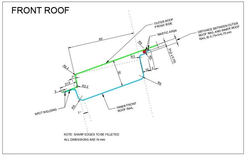
Firstly we work on the outer roof front side:
- Use law of extension extendend the flange with 7degg angle.
- Again use law extension to create the flange of 21.5 mm .
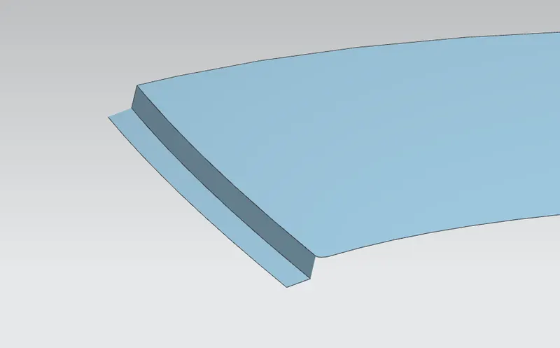
After completion of front roof ouer panel we will work on inner front roof rail.
- firstly we create a componet in the assembly part to work .
- Now use wave geometry link to take the referenc from the outer roof.
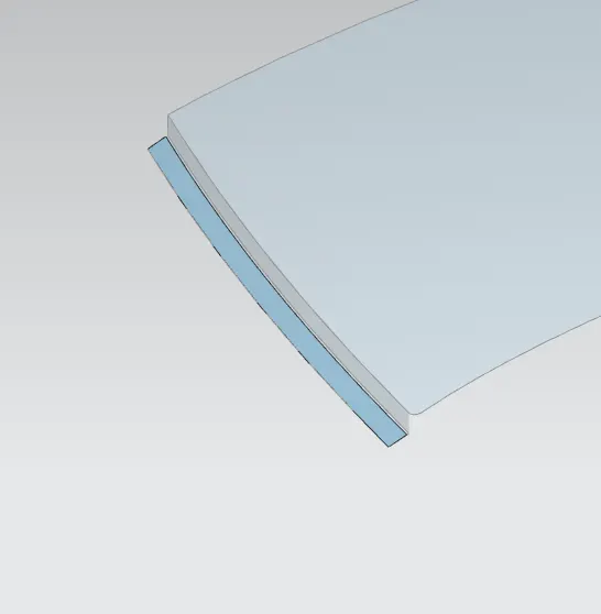
- Offset the surface to 0.75+0.75mm to create flange as per master section.
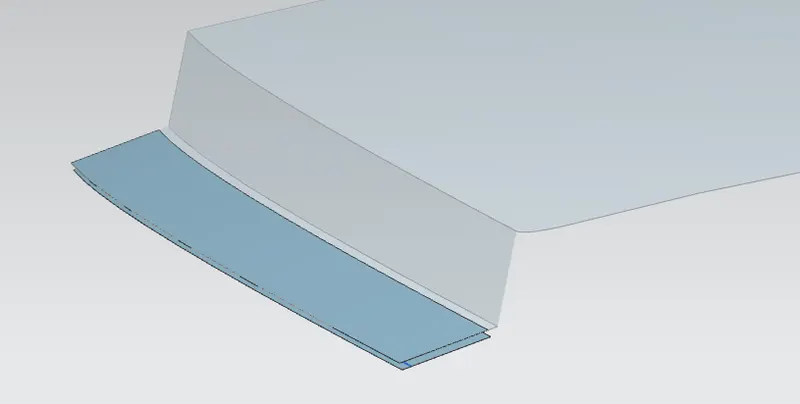
offset the curve to 2mm and trim the sheet.
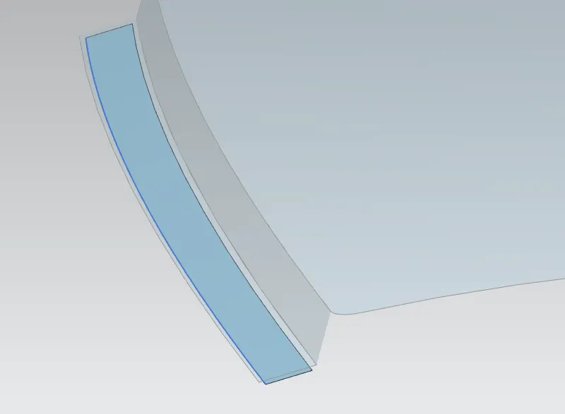
Now again use wave geometry linke and offset to 32 mm .
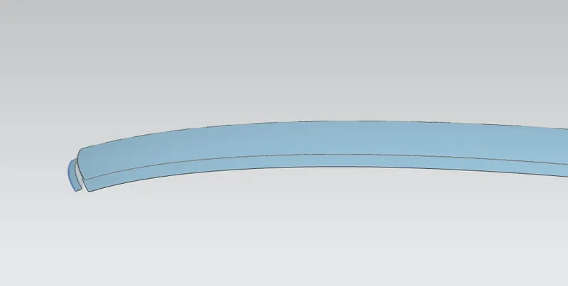
Now we will use law of extension to intersect the both the surface and use trim and extent the sheet to get required shape.
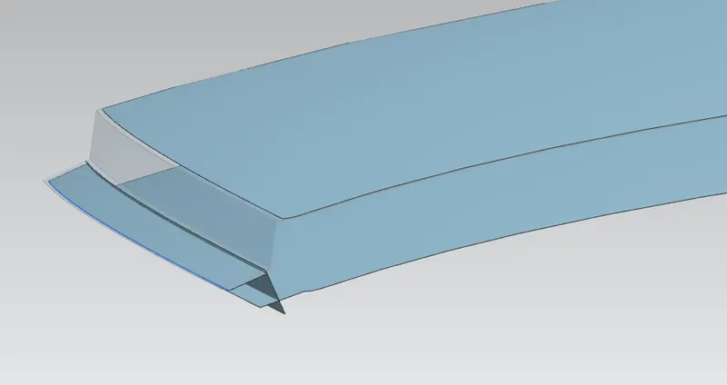
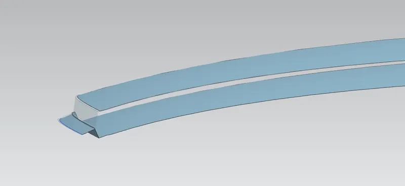
Now we will offset the curve o requird length as metioned in the maste section and trim the sheet and use of through curve join the sheet and gave blend .
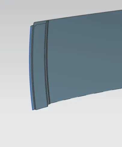
So that i will create the emboss to gave the strength to the sheet
For the i create a sketch and eboss and remove the material.
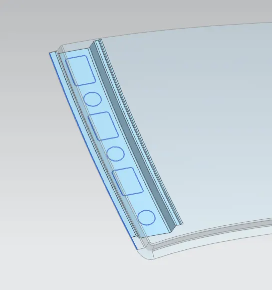
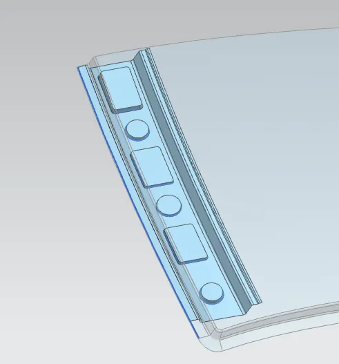
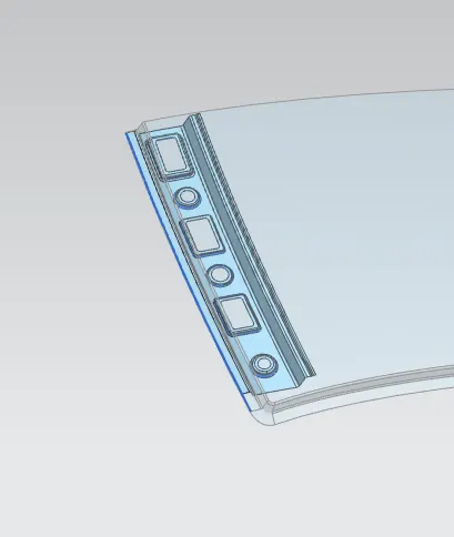
so that inner front roof rail is done.
Now we will go for the rear Roof.
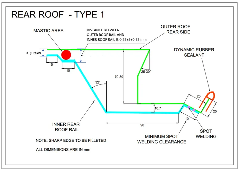
Now firstly we work on the outer roof rear side.
- using law of extension giving the angle of 25 to 30 degg to 40mm length.
- create another law o extension to 40 mm.
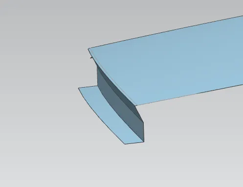
- create another two law o extension from data of master section.
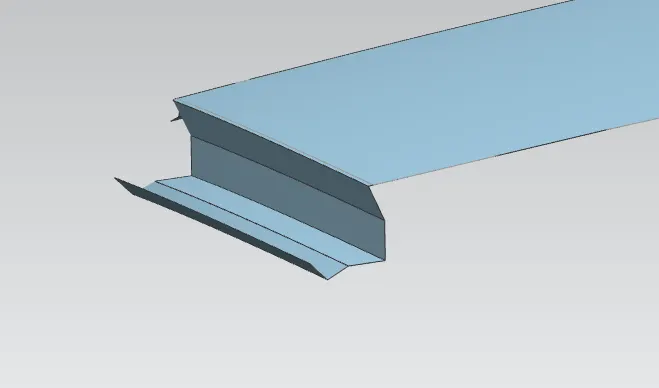
- Now i gave all the blends to all the surfaces.
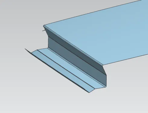
- so that outer roof rear side.
Now we will work on inner rear roof rail useing the master section.
- firstly we create a componet in the assembly part to work .
- Now use wave geometry link to take the referenc from the outer roof.
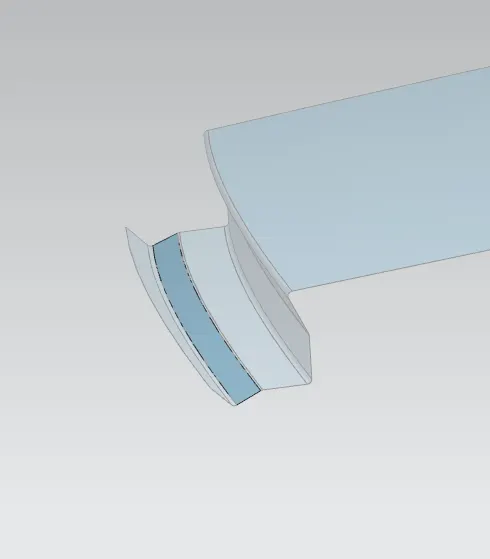
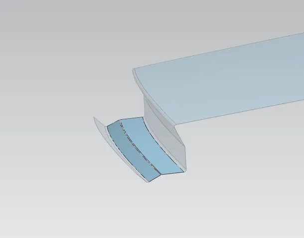
After that offset the both the surfavcsurface to required length mentioned in the master section and trim the sheet and use throgh curve join the sheet .
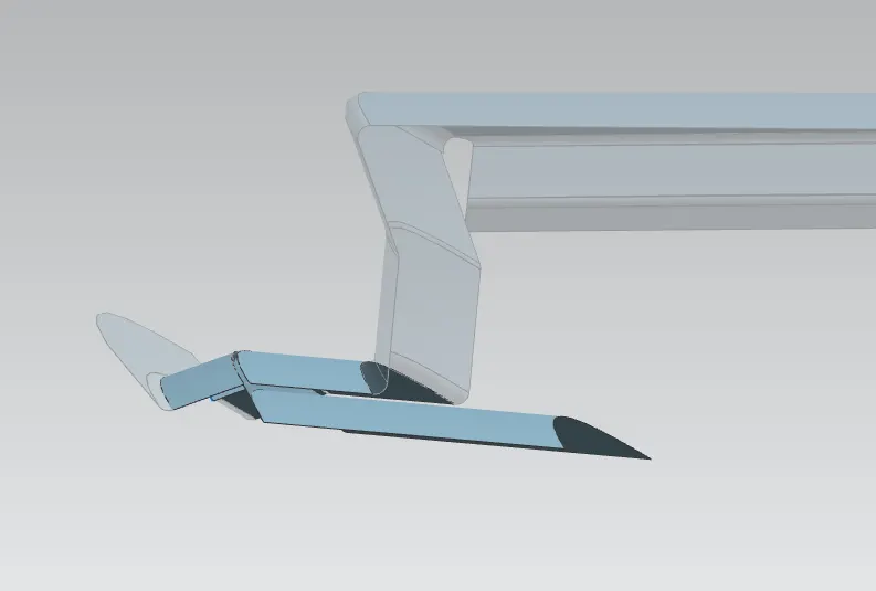
now use wave geometry linker to tak reference of the roof to rest flange.
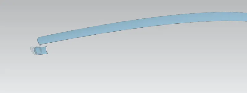
now offset sheet and trim the sheet as per master section and use through curve to crreate a surface and gave all tha blends.
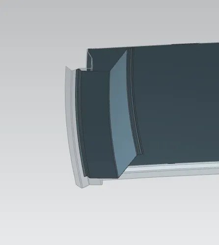
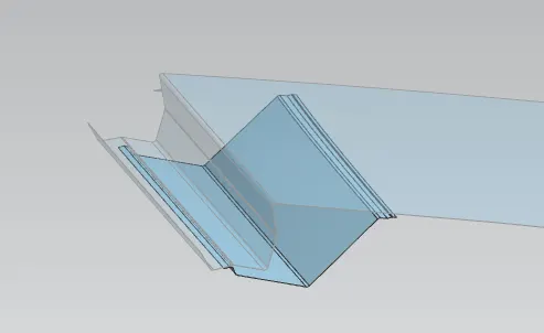
Now our flange is create.
So that i will create the emboss to gave the strength to the sheet
For the i create a sketch and eboss and remove the material.
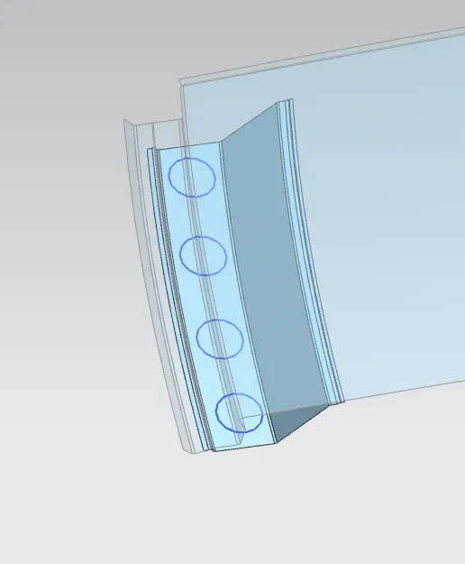
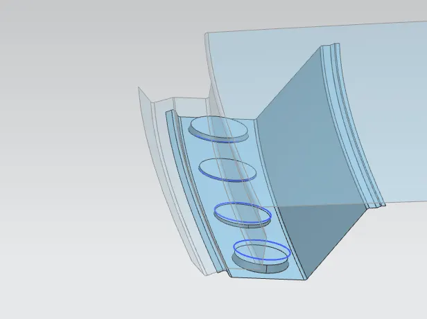
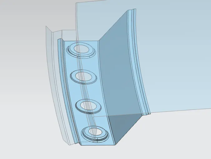
So that my rear roof to done .
now we will move to centre Roof.
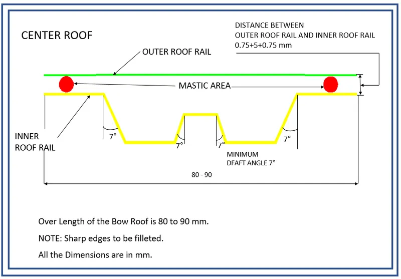
- Firstly use wave geometry linker to take a reference from roof outer sheet.
- create the datam plane and create intersection line.
- Then make 2 offset the surfaec as mentioned in the master section.
- offset the curve to requried length and trim the sheet.
- use of through curve create the surfaec and gave all the blends .
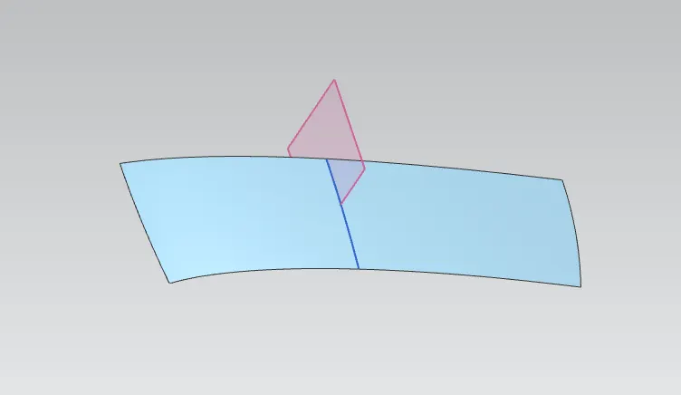
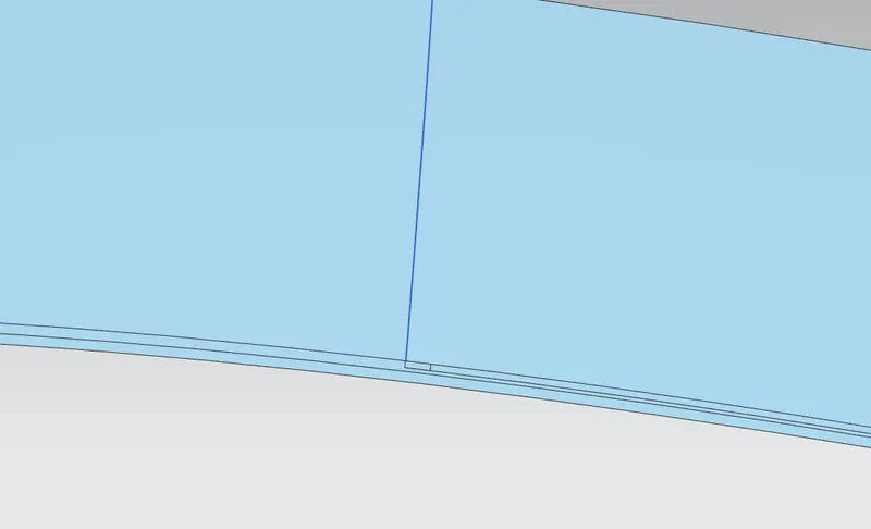
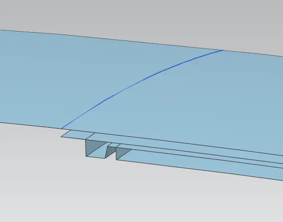
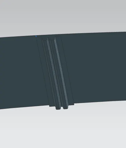
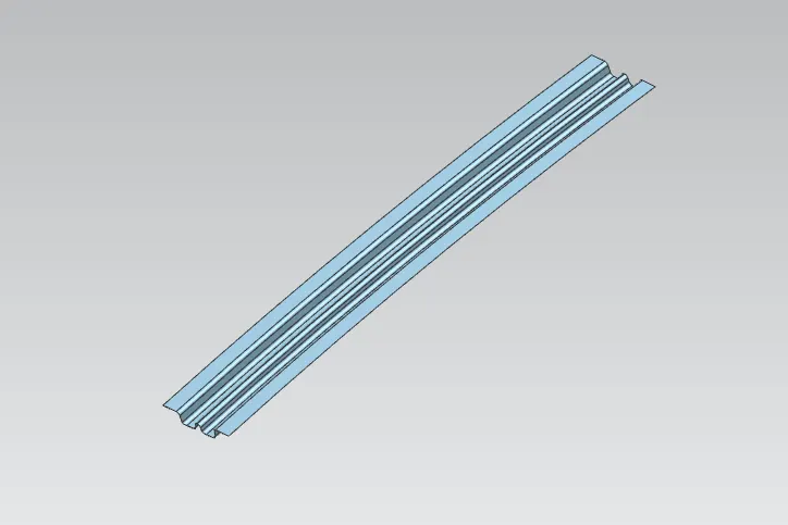
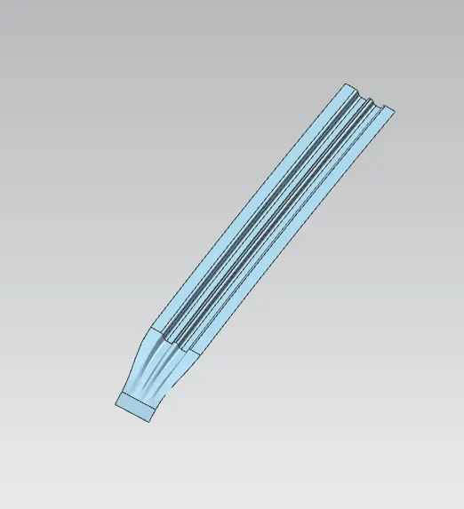
centre Roof rail is done
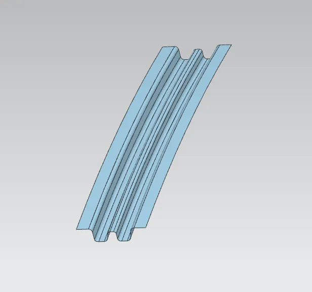
Now we will create BOW roof 1
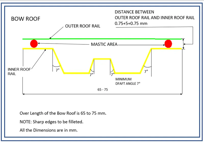
- Firstly use wave geometry linker to take a reference from roof outer sheet.
- create the datam plane and create intersection line.
- Then make 2 offset the surfaec as mentioned in the master section.
- offset the curve to requried length and trim the sheet.
- use of through curve create the surfaec and gave all the blends .
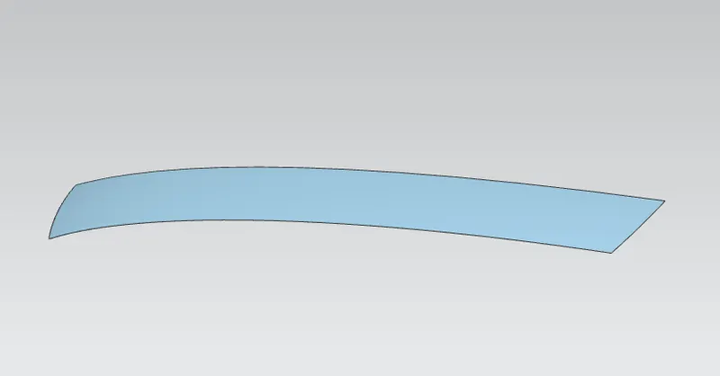
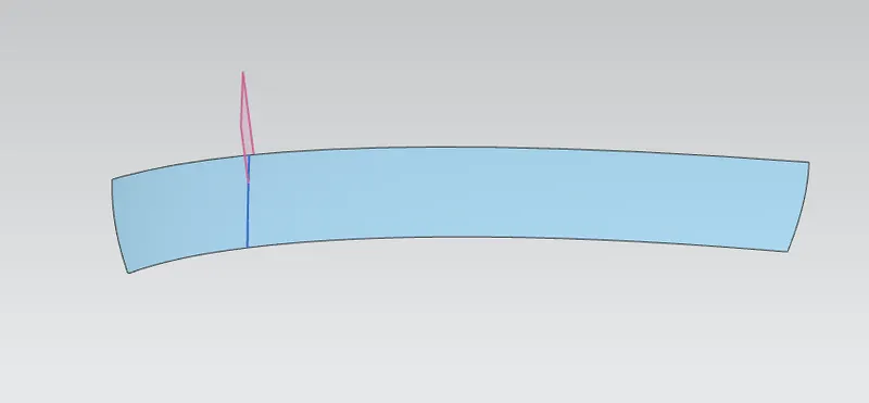
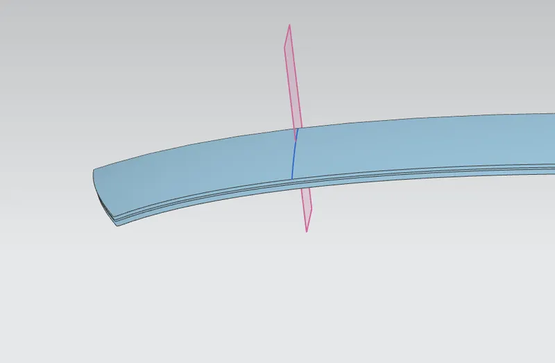
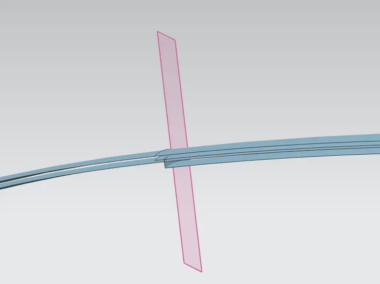
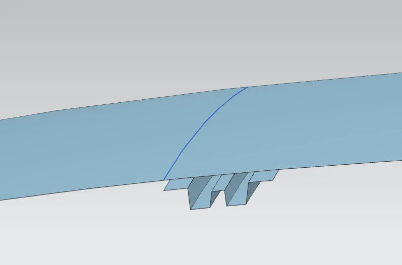
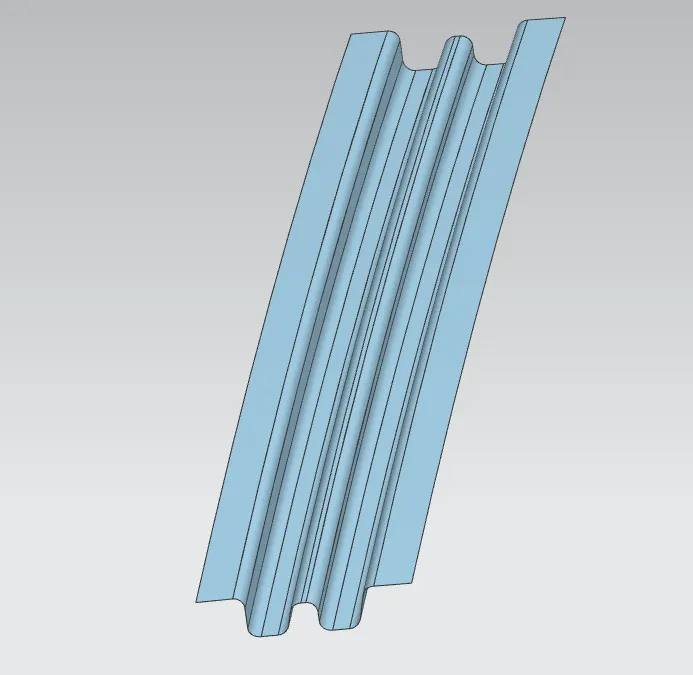
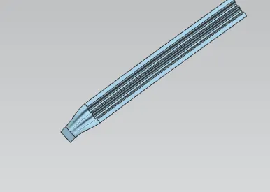
So that BOW roof 1 is done
Similarly we will create the BOW Roof 2 useing same master section.
- Firstly use wave geometry linker to take a reference from roof outer sheet.
- create the datam plane and create intersection line.
- Then make 2 offset the surfaec as mentioned in the master section.
- offset the curve to requried length and trim the sheet.
- use of through curve create the surfaec and gave all the blends .
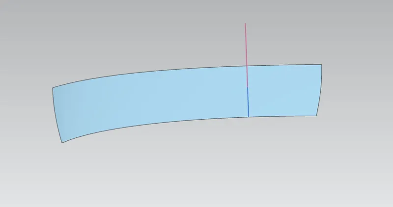
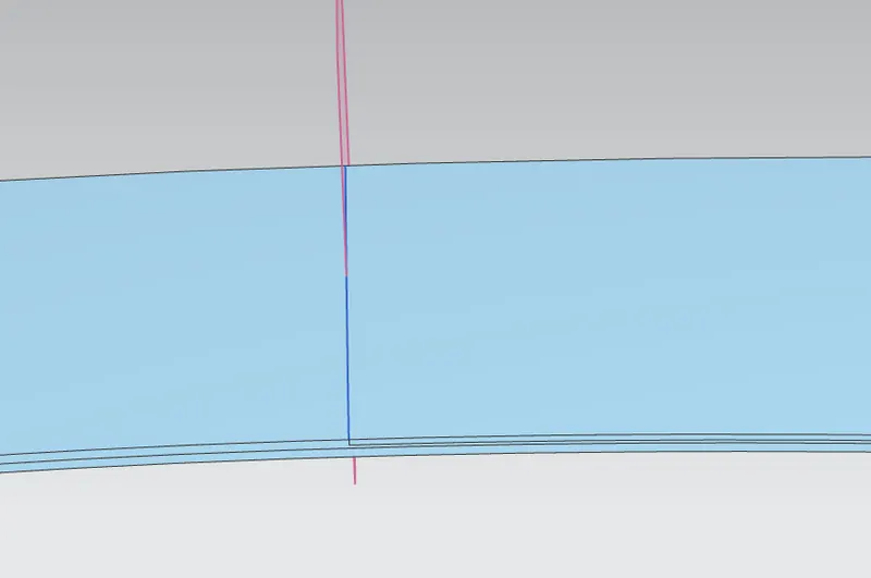
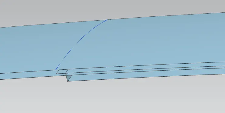
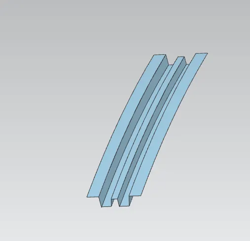
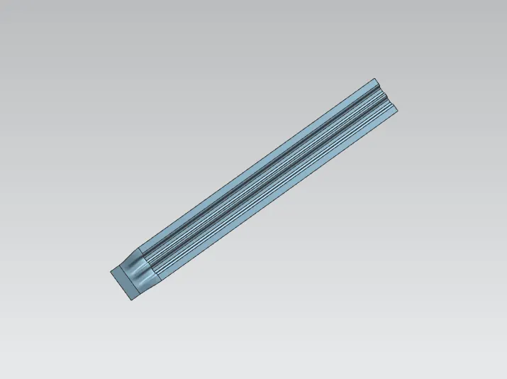
So that BOW Roof 2 also done.
NOW we extent all the sheets individually and trim the sheets and mirror by using the mirror geometry and screw it.
ROOF
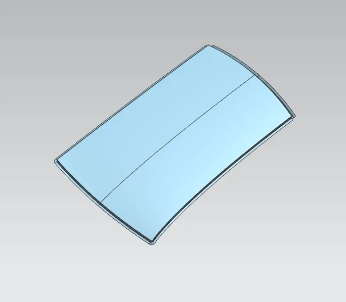
thicken to 0.75 mm.
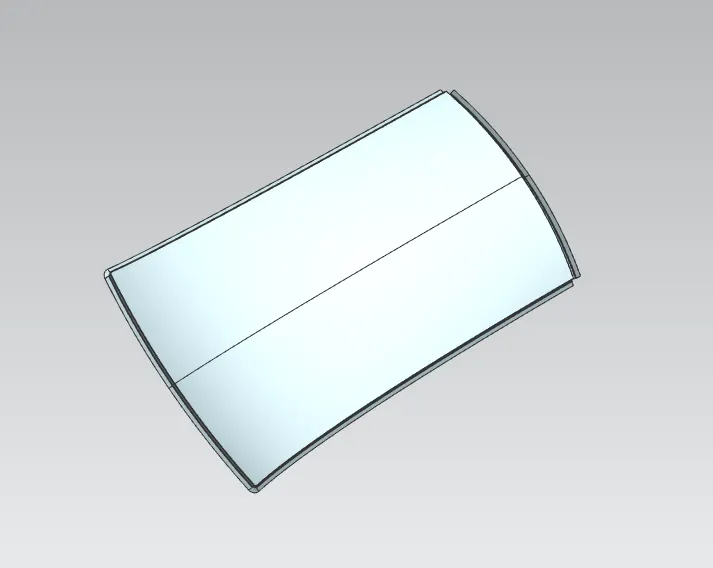
Front Roof.
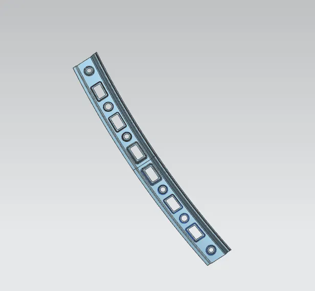
Thicken to 0.75 mm
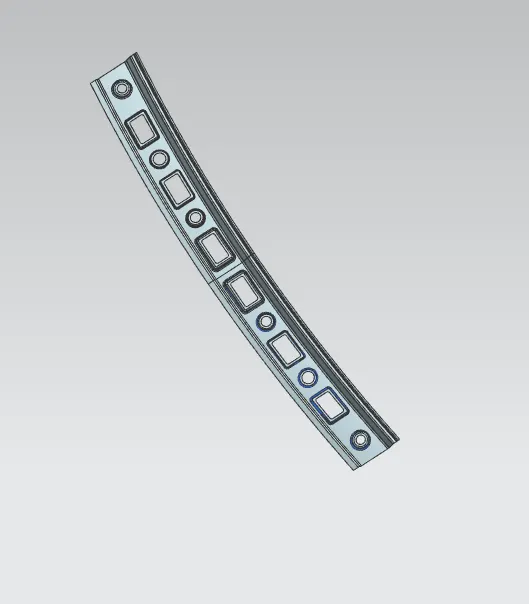
Rear Roof.
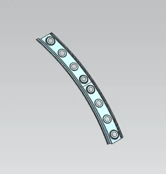
THicken to 0.75mm
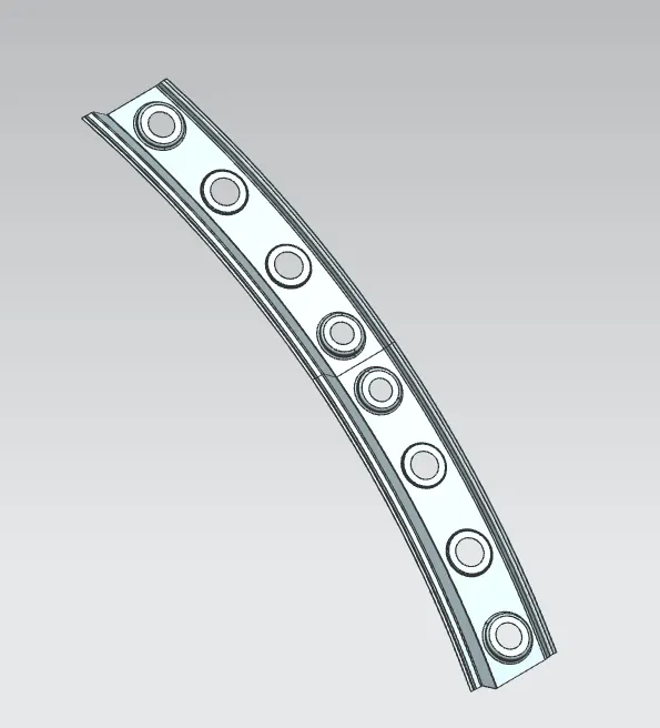
Centre Roof:
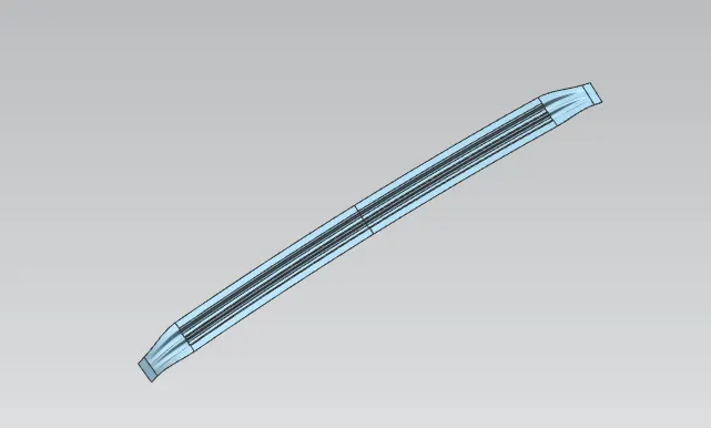
Thicken to 0.75 mm
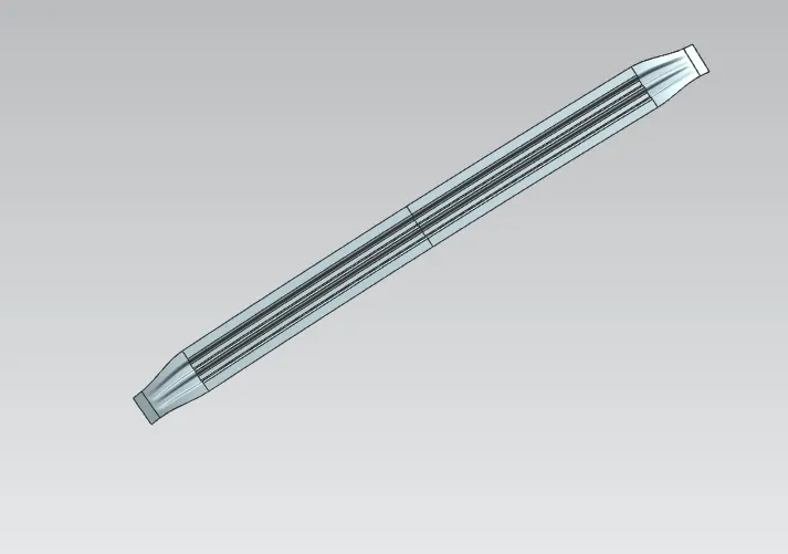
BOW Roof 1
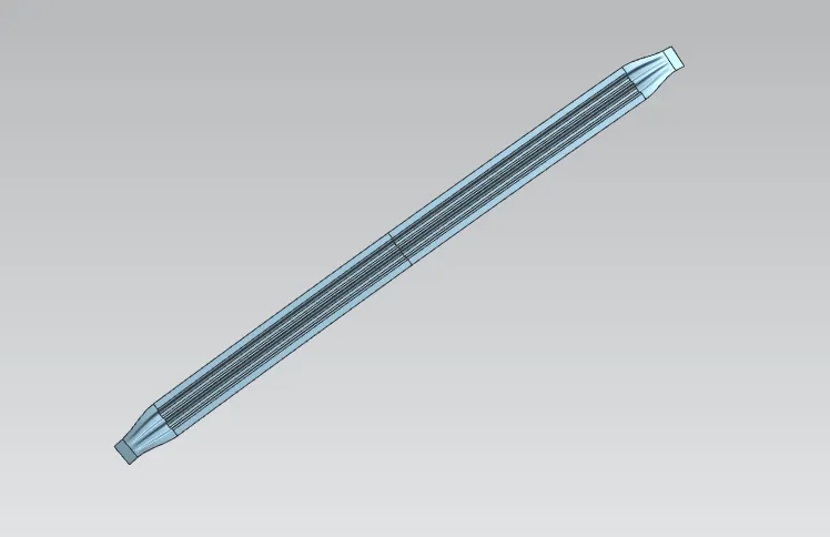
Thiken to 0.75 mm
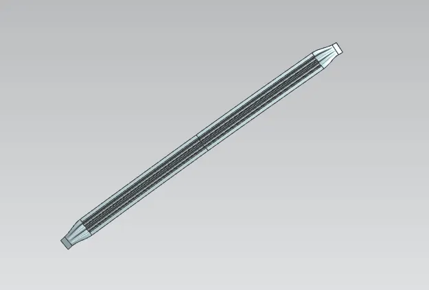
BOW Roof 2
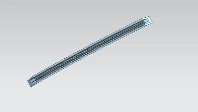
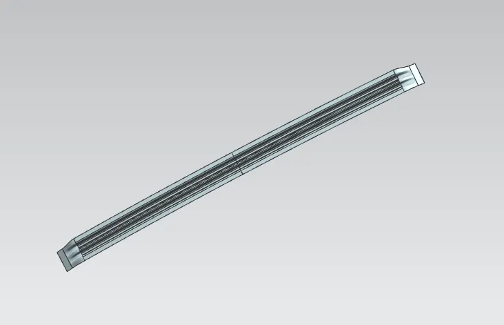
Roof assembly:
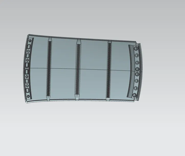
so that my Roof Assembly is created.
Curvature study of the roof: By Heat distortion criteria
Done to predict where the bow rails should be placed as per the given loading conditions or criteria. Heat distortion criteria is predicting weather for a given fixed loading will the component undergo failure due to buckling or bending. The heat distortion or deflection temperature of the material is the temperature above which the component cannot be used for structural application as it softens and fails due to elevated temperatures and load. The failure may cause cracking of welds, bending etc
Bow–Roof Prediction Formula
W = [1.73 x 10^(-3) x L] + [1.85 x 10^(-8) x (R^2)/t] + [ 1.10x10^(-3) x l] - 2.68
Where,
L = Roof Length in X-Direction[mm](Roof dimension in 0-Y)
R = Roof curvature
R = 2(Rx*Ry)/(Rx+Ry)
Rx = X curvature
Ry = Y curvature
t = Roof plate thickness [mm]
l = Bow Roof Span [mm]
Judgment Condition
OK< 2.7
Front Roof to BOW 1(Section 1)
- Firstly take all the required variable with are menstioned in the fromula
L = Roof Length in X-Direction[mm](Roof dimension in 0-Y)
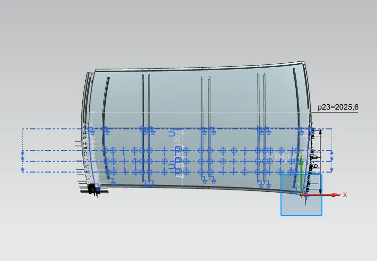
L = 2025.6 mm
t = Roof plate thickness [mm]
t=0.75 m
l = Bow Roof Span [mm]
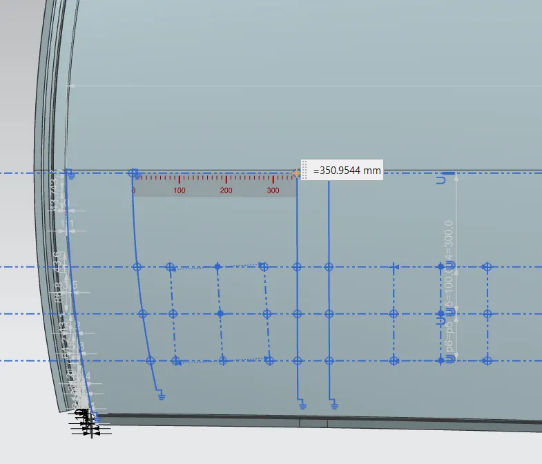
I = 350.9544 mm
R = Roof curvature
R = 2(Rx*Ry)/(Rx+Ry)
Rx = X curvature
Ry = Y curvature
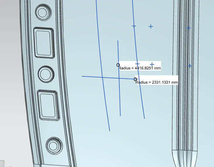
Rx = 4416.8251 mm
Ry = 2331.131 mm
Now i get all the required data :
W = [1.73 x 10^(-3) x L] + [1.85 x 10^(-8) x (R^2)/t] + [ 1.10x10^(-3) x l] - 2.68
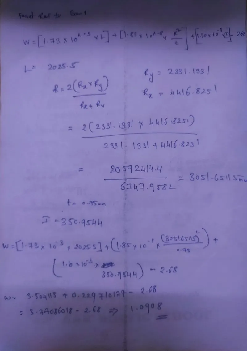
Front Roof to BOW 1(Section 1)
W =1.0908
BOW 1 to centre roof (Section 2)
Bow–Roof Prediction Formula
W = [1.73 x 10^(-3) x L] + [1.85 x 10^(-8) x (R^2)/t] + [ 1.10x10^(-3) x l] - 2.68
Where,
L = Roof Length in X-Direction[mm](Roof dimension in 0-Y)
R = Roof curvature
R = 2(Rx*Ry)/(Rx+Ry)
Rx = X curvature
Ry = Y curvature
t = Roof plate thickness [mm]
l = Bow Roof Span [mm]
Judgment Condition
OK< 2.7
- Firstly take all the required variable with are menstioned in the fromula
L = Roof Length in X-Direction[mm](Roof dimension in 0-Y)
L = 2025.6 mm
t = Roof plate thickness [mm]
t=0.75 m
l = Bow Roof Span [mm]
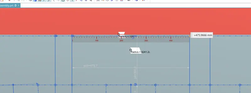
I = 475.966
R = Roof curvature
R = 2(Rx*Ry)/(Rx+Ry)
Rx = X curvature
Ry = Y curvature
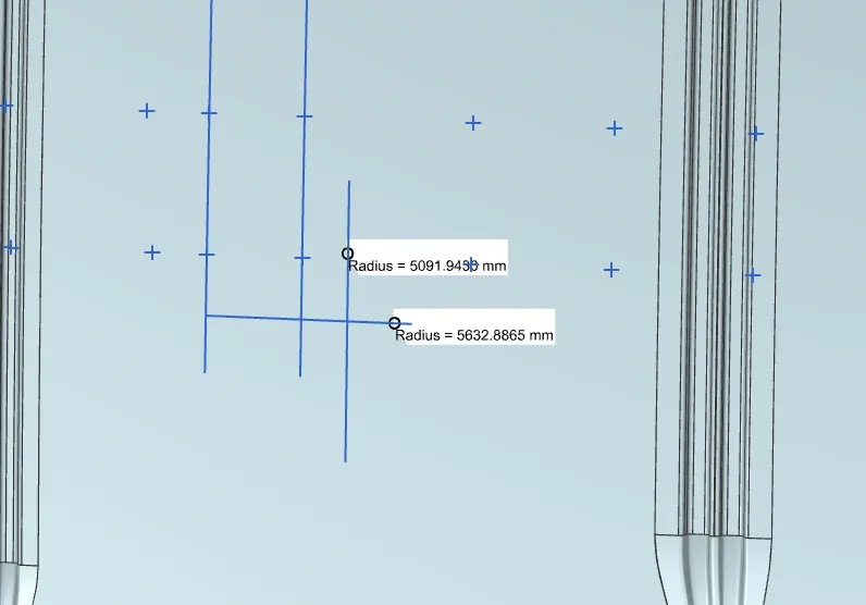
Rx = 5091.9430 mm
Ry = 5632.8865 mm
Now i get all the required data :
W = [1.73 x 10^(-3) x L] + [1.85 x 10^(-8) x (R^2)/t] + [ 1.10x10^(-3) x l] - 2.68
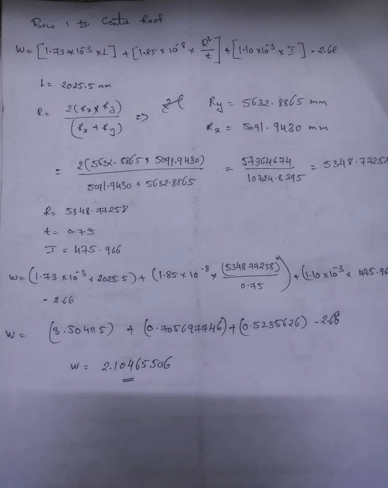
BOW 1 to centre roof (Section 2)
W =2.10465506
Centre Roof to BOW Roof 2(Section 3):
Bow–Roof Prediction Formula
W = [1.73 x 10^(-3) x L] + [1.85 x 10^(-8) x (R^2)/t] + [ 1.10x10^(-3) x l] - 2.68
Where,
L = Roof Length in X-Direction[mm](Roof dimension in 0-Y)
R = Roof curvature
R = 2(Rx*Ry)/(Rx+Ry)
Rx = X curvature
Ry = Y curvature
t = Roof plate thickness [mm]
l = Bow Roof Span [mm]
Judgment Condition
OK< 2.7
- Firstly take all the required variable with are menstioned in the fromula
L = Roof Length in X-Direction[mm](Roof dimension in 0-Y)
L = 2025.6 mm
t = Roof plate thickness [mm]
t=0.75 m
l = Bow Roof Span [mm]
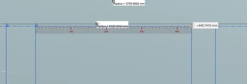
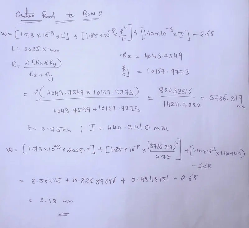
I = 440.7410 mm
R = Roof curvature
R = 2(Rx*Ry)/(Rx+Ry)
Rx = X curvature
Ry = Y curvature
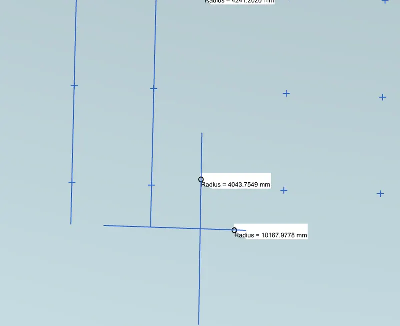
Rx = 43.7549 mmmm
Ry = 10167.973 mm
Now i get all the required data :
W = [1.73 x 10^(-3) x L] + [1.85 x 10^(-8) x (R^2)/t] + [ 1.10x10^(-3) x l] - 2.68
Centre Roof to BOW Roof 2(Section 3):
W =2.13
BOW Roof 2 Rear Roof Section 4):
Bow–Roof Prediction Formula
W = [1.73 x 10^(-3) x L] + [1.85 x 10^(-8) x (R^2)/t] + [ 1.10x10^(-3) x l] - 2.68
Where,
L = Roof Length in X-Direction[mm](Roof dimension in 0-Y)
R = Roof curvature
R = 2(Rx*Ry)/(Rx+Ry)
Rx = X curvature
Ry = Y curvature
t = Roof plate thickness [mm]
l = Bow Roof Span [mm]
Judgment Condition
OK< 2.7
- Firstly take all the required variable with are menstioned in the fromula
L = Roof Length in X-Direction[mm](Roof dimension in 0-Y)
L = 2025.6 mm
t = Roof plate thickness [mm]
t=0.75 m
l = Bow Roof Span [mm]
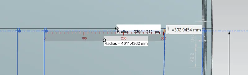
I = 302.9454
R = Roof curvature
R = 2(Rx*Ry)/(Rx+Ry)
Rx = X curvature
Ry = Y curvature
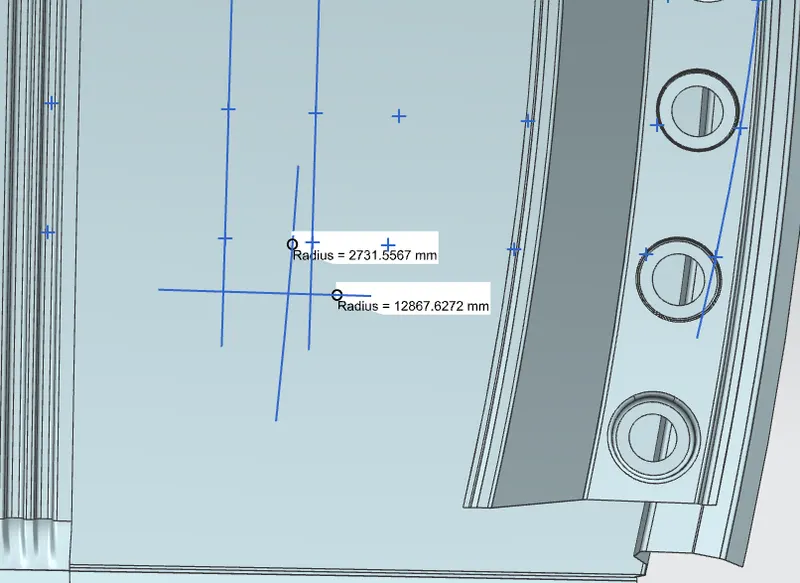
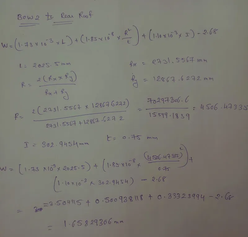
Rx = 2731.5567 mmmm
Ry = 12867.6272 mm
Now i get all the required data :
W = [1.73 x 10^(-3) x L] + [1.85 x 10^(-8) x (R^2)/t] + [ 1.10x10^(-3) x l] - 2.68
BOW Roof 2 Rear Roof Section 4)
W =1.65829
|
Sr.No. |
Bow |
Rx(mm) |
Ry(mm) |
R(mm) |
I(mm) |
W |
Judgment |
|
1. |
FRR and Bow 1 |
4416.8251 |
2331.1331 |
3051.65115 |
350.9544 |
1.0908 |
OK |
|
2. |
BOW 1 to center Roof |
5091.9430 |
65632.8865 |
5348.77258 |
475.966 |
2.1046 |
OK |
|
3. |
Centre Roof to BOW 2 | 4043.7549 |
10167.9773 |
5786.319 |
440.7410 |
2.13 |
OK |
|
4. |
Bow2 to Rear Roof |
2731.5567 |
12867.6272 |
4506.47335 |
302.9454 |
1.658 |
OK |
Hence, the design is safe as per Heat distortion criteria for the current position of Roof Bows.
- By Snowed Criteria:
A crucial design criteria which is very important in the usable life of a vehicle. In the colder regions of the world where it snows heavily during winters and are prone to storms, the snow accumulated on the roof of a standing/parked vehicle may cause permanent damage. The support structure of the roof that is the roof bows and centre roof reinforcement should be placed suitably such that it could withstand the weight of the snow. Instead of making the roof rigid and heavy which will cost more and would make the vehicle less fuel efficient, it is allowed to flex up to a limit which absorbs a bit of the energy similar to a spring. When the snow is cleared and there is no more load on the roof by design it should regain its original position.
Snow Load Prediction Formula
Qr = [Iy x t2] / [α x s x [(Rx + Ry)/2]2 x 10-8]
Note: The Qr value given over here is correct. There was a typo error in the formula given in the video.
Where,
α = My x Lx2 x 10-12 , My = Y(Ly-Y)
t = Roof plate thickness [mm]
Ly = Distance between the front and rear roof Rails on the Vehicle along with 0Y[mm]
Length of Roof panel with the center point between Roof rail Front /Rear as the front and rear reference point.
Lx = Distance between the Left and Right end of the roof on the Roof BOW [mm]
The width of the roof panel is exposed on the surface.
Y = Distance front Front Roof Rail to Roof BOW[mm]
s = Distance for which Roof BOW bears divided load [mm]
s = L1/2 + L2/2
Iy = Geometrical moment of inertia of Roof BOW (Y cross-section )[mm4]
Rx = Lateral direction curvature radius of roof panel Y cross-section on Roof BOW [mm]
Roof panel curvature Radius of the Length Lx in Front view
Ry = Longitudinal Direction curvature radius of the Roof panel X cross-section on Roof BOW [mm]
Roof panel X curvature radius of length s in Side view
Judgment condition
Qr ≥ 3.1
Front Roof to BOW 1(Section 1)
- Firstly take all the required variable with are menstioned in the fromula
α = My x Lx2 x 10-12 , My = Y(Ly-Y)
t = Roof plate thickness [mm]
t=0.75 mm
Ly = Distance between the front and rear roof Rails on the Vehicle along with 0Y[mm]
Length of Roof panel with the center point between Roof rail Front /Rear as the front and rear reference point.
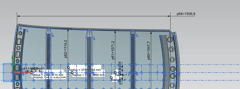
Ly = 1936.8
Lx = Distance between the Left and Right end of the roof on the Roof BOW [mm]
The width of the roof panel is exposed on the surface.
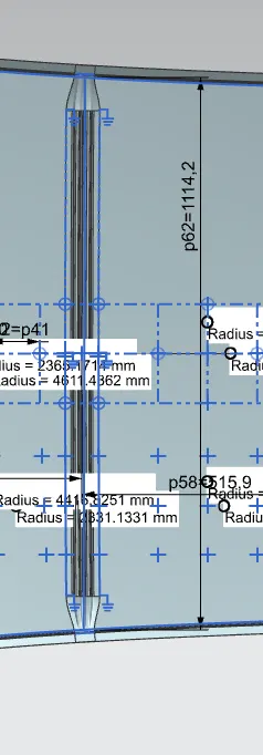
Lx = 1114.2 mm
Y = Distance front Front Roof Rail to Roof BOW[mm]
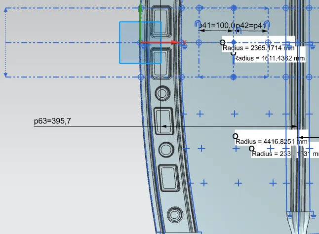
Y = 395.7
s = Distance for which Roof BOW bears divided load [mm]
s = L1/2 + L2/2
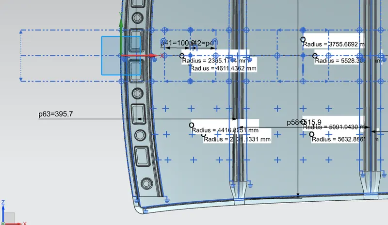
L1 = 395.9
L2 = 515.9
Iy = Geometrical moment of inertia of Roof BOW (Y cross-section )[mm4]
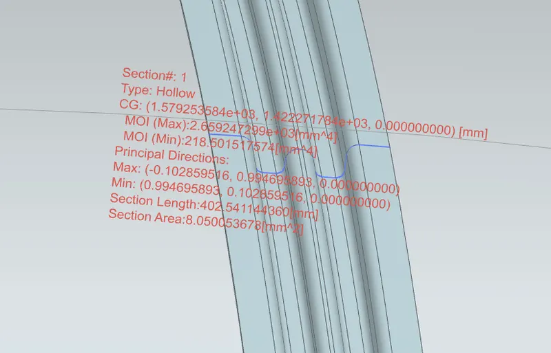
I = 218.501517mm^4
Rx = Lateral direction curvature radius of roof panel Y cross-section on Roof BOW [mm]
Roof panel curvature Radius of the Length Lx in Front view
Ry = Longitudinal Direction curvature radius of the Roof panel X cross-section on Roof BOW [mm]
Roof panel X curvature radius of length s in Side view
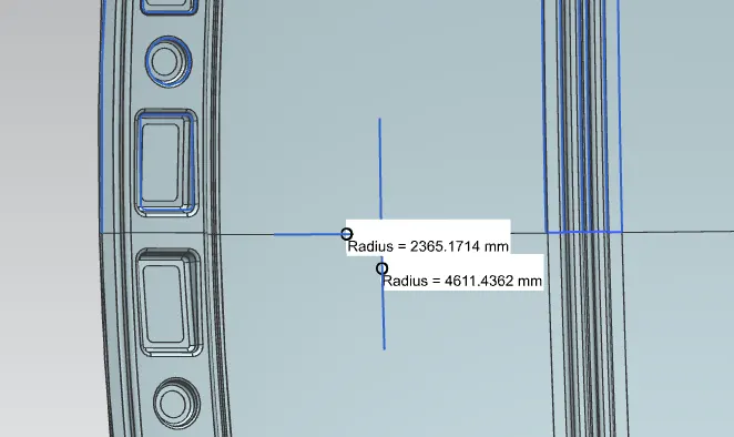
Rx= 4611.4362
Ry = 2365.1714
Qr = [Iy x t2] / [α x s x [(Rx + Ry)/2]2 x 10-8]
α = My x Lx2 x 10-12 , My = Y(Ly-Y)
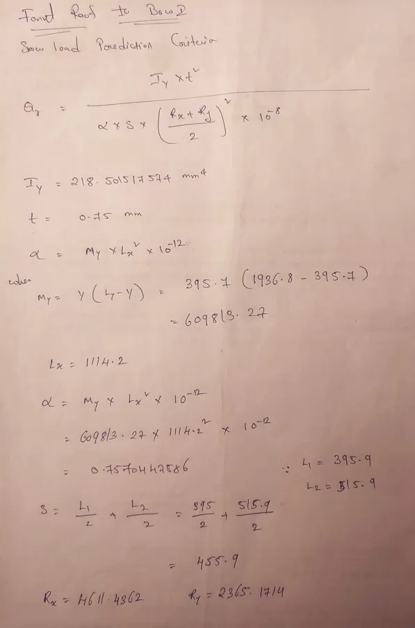
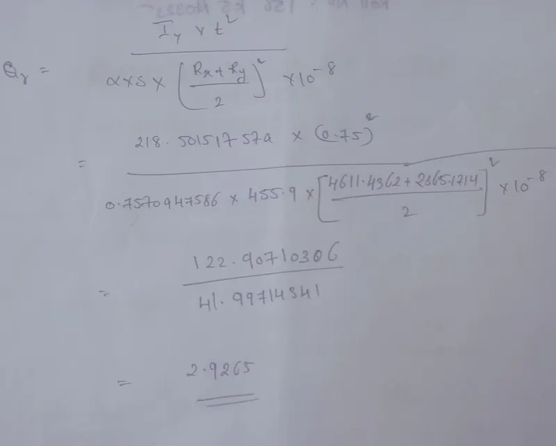
Qr=2.9265
BOW 1 to center Roof (Section 2)
Snow Load Prediction Formula
Qr = [Iy x t2] / [α x s x [(Rx + Ry)/2]2 x 10-8]
Note: The Qr value given over here is correct. There was a typo error in the formula given in the video.
Where,
α = My x Lx2 x 10-12 , My = Y(Ly-Y)
t = Roof plate thickness [mm]
Ly = Distance between the front and rear roof Rails on the Vehicle along with 0Y[mm]
Length of Roof panel with the center point between Roof rail Front /Rear as the front and rear reference point.
Lx = Distance between the Left and Right end of the roof on the Roof BOW [mm]
The width of the roof panel is exposed on the surface.
Y = Distance front Front Roof Rail to Roof BOW[mm]
s = Distance for which Roof BOW bears divided load [mm]
s = L1/2 + L2/2
Iy = Geometrical moment of inertia of Roof BOW (Y cross-section )[mm4]
Rx = Lateral direction curvature radius of roof panel Y cross-section on Roof BOW [mm]
Roof panel curvature Radius of the Length Lx in Front view
Ry = Longitudinal Direction curvature radius of the Roof panel X cross-section on Roof BOW [mm]
Roof panel X curvature radius of length s in Side view
Judgment condition
Qr ≥ 3.1
- Firstly take all the required variable with are menstioned in the fromula
α = My x Lx2 x 10-12 , My = Y(Ly-Y)
t = Roof plate thickness [mm]
t=0.75mm
Ly = Distance between the front and rear roof Rails on the Vehicle along with 0Y[mm]
Length of Roof panel with the center point between Roof rail Front /Rear as the front and rear reference point.
Ly = 1936.8
Lx = Distance between the Left and Right end of the roof on the Roof BOW [mm]
The width of the roof panel is exposed on the surface.
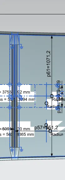
Lx = 1071.2
Y = Distance front Front Roof Rail to Roof BOW[mm]
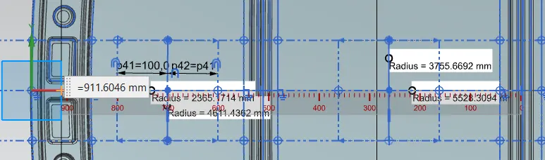
Y =911.604 mm
s = Distance for which Roof BOW bears divided load [mm]
s = L1/2 + L2/2
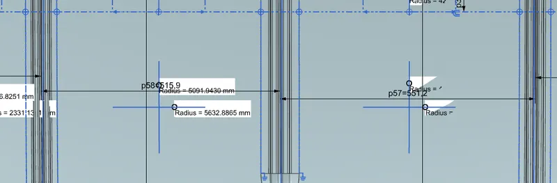
L1= 515.9 mm
L2 = 551.2 mm
Iy = Geometrical moment of inertia of Roof BOW (Y cross-section )[mm4]
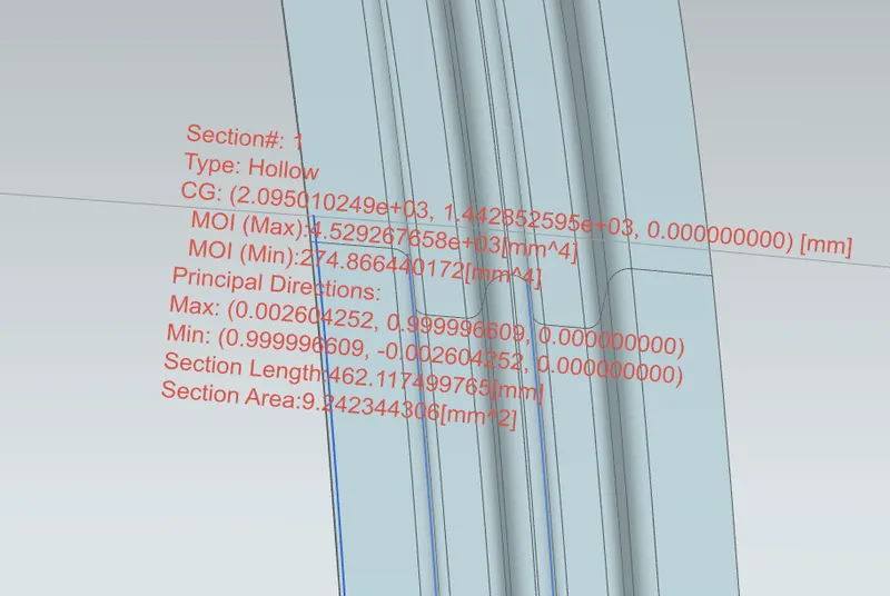
Iy = 274.86644017 mm^4
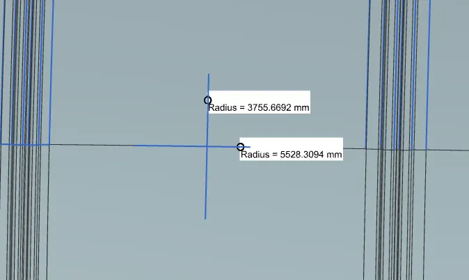
Rx = Lateral direction curvature radius of roof panel Y cross-section on Roof BOW [mm]
Roof panel curvature Radius of the Length Lx in Front view
Ry = Longitudinal Direction curvature radius of the Roof panel X cross-section on Roof BOW [mm]
Roof panel X curvature radius of length s in Side view
Snow Load Prediction Formula
Qr = [Iy x t2] / [α x s x [(Rx + Ry)/2]2 x 10-8]
α = My x Lx2 x 10-12 , My = Y(Ly-Y)
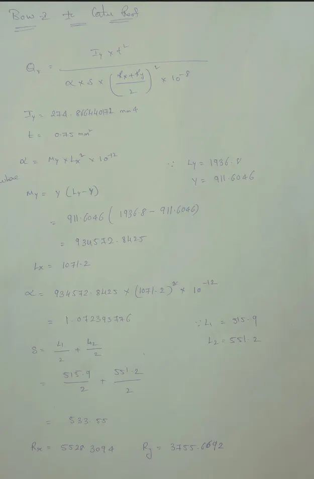
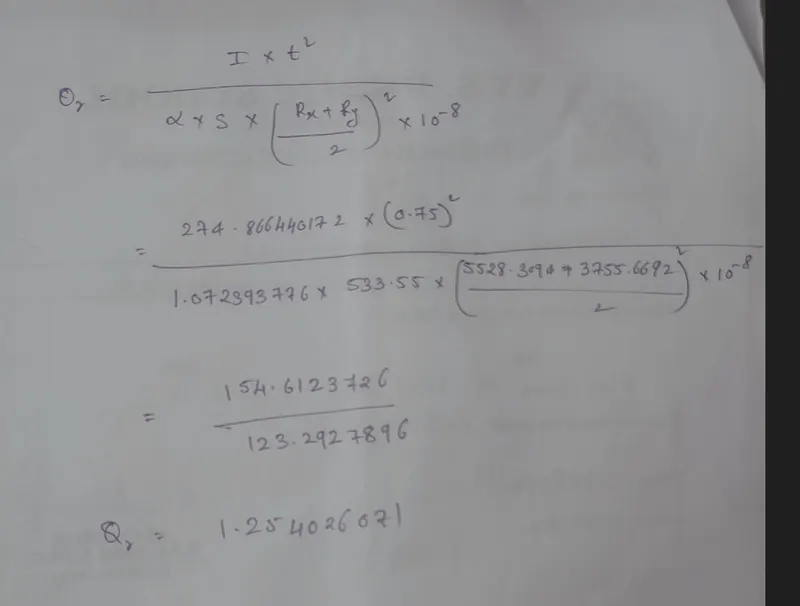
Qr =1.25
Center Roof to BOW 2(Section 3)
Snow Load Prediction Formula
Qr = [Iy x t2] / [α x s x [(Rx + Ry)/2]2 x 10-8]
Note: The Qr value given over here is correct. There was a typo error in the formula given in the video.
Where,
α = My x Lx2 x 10-12 , My = Y(Ly-Y)
t = Roof plate thickness [mm]
Ly = Distance between the front and rear roof Rails on the Vehicle along with 0Y[mm]
Length of Roof panel with the center point between Roof rail Front /Rear as the front and rear reference point.
Lx = Distance between the Left and Right end of the roof on the Roof BOW [mm]
The width of the roof panel is exposed on the surface.
Y = Distance front Front Roof Rail to Roof BOW[mm]
s = Distance for which Roof BOW bears divided load [mm]
s = L1/2 + L2/2
Iy = Geometrical moment of inertia of Roof BOW (Y cross-section )[mm4]
Rx = Lateral direction curvature radius of roof panel Y cross-section on Roof BOW [mm]
Roof panel curvature Radius of the Length Lx in Front view
Ry = Longitudinal Direction curvature radius of the Roof panel X cross-section on Roof BOW [mm]
Roof panel X curvature radius of length s in Side view
Judgment condition
Qr ≥ 3.1
- Firstly take all the required variable with are menstioned in the fromula
α = My x Lx2 x 10-12 , My = Y(Ly-Y)
t = Roof plate thickness [mm]
t=0.75 mm
Ly = Distance between the front and rear roof Rails on the Vehicle along with 0Y[mm]
Length of Roof panel with the center point between Roof rail Front /Rear as the front and rear reference point.
Ly = 1936.8
Lx = Distance between the Left and Right end of the roof on the Roof BOW [mm]
The width of the roof panel is exposed on the surface.
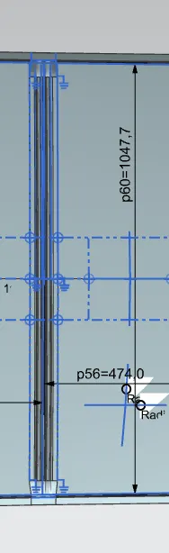
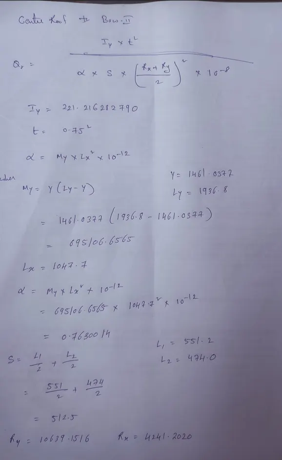
Lx = 1047.7 mm
Y = Distance front Front Roof Rail to Roof BOW[mm]
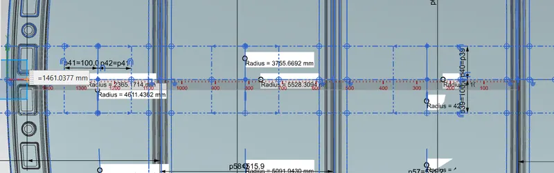
Y = 1461.0377
s = Distance for which Roof BOW bears divided load [mm]
s = L1/2 + L2/2
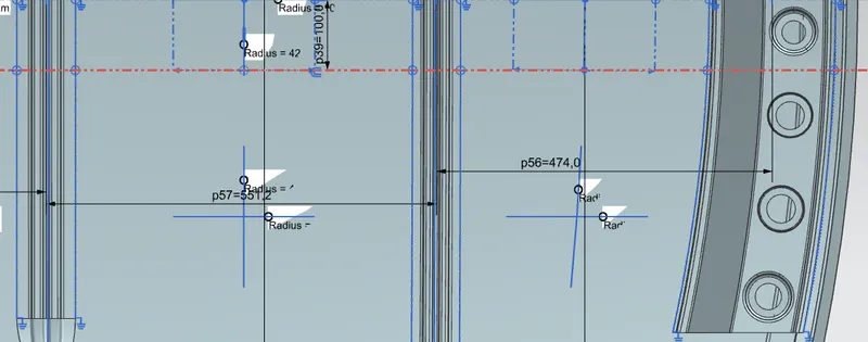
L 1 = 551.2
L 2 = 474.0
Iy = Geometrical moment of inertia of Roof BOW (Y cross-section )[mm4]
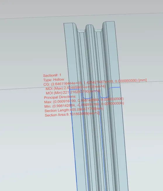
I = 221.216282790 mm^4
Rx = Lateral direction curvature radius of roof panel Y cross-section on Roof BOW [mm]
Roof panel curvature Radius of the Length Lx in Front view
Ry = Longitudinal Direction curvature radius of the Roof panel X cross-section on Roof BOW [mm]
Roof panel X curvature radius of length s in Side view
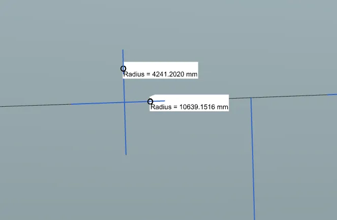
Rx = 4241.2020
Ry = 10639.1516
Snow Load Prediction Formula
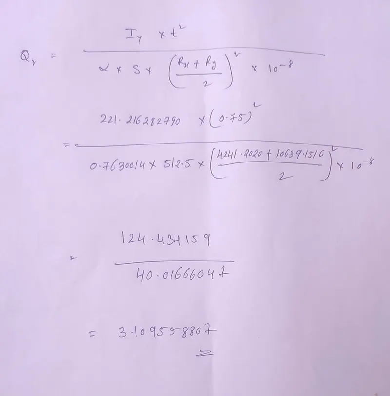
Qr = [Iy x t2] / [α x s x [(Rx + Ry)/2]2 x 10-8]
α = My x Lx2 x 10-12 , My = Y(Ly-Y)
|
Roof Rails |
Iy(mm) |
Lx(mm) |
Ly(mm) |
L1(mm) |
L2(mm) |
Rx(mm) |
Ry(mm) |
t(mm) |
Y(mm) |
S |
My |
α |
Qr |
Result |
|
FR-BOW_1 |
218.501 |
1114.2 |
1936.8 |
395.9 |
515.9 |
4611.4362 |
2365.1714 |
0.75 |
395.7 |
455.9 |
609813.27 |
0.75704 |
2.92 |
NG |
|
BOW_1-CR |
274.866 |
1071.2 |
1936.58 |
515.9 |
551.2 |
3755.6692 |
5528.3094 |
0.75 |
911.6046 |
533.55 |
3472.8425 |
1.0723 |
1.25 |
NG |
|
CR-BOW_2 |
221.216 |
1047.7 |
1936.8 |
551.2 |
474.0 |
4241.2020 |
10639.1516 |
0.75 |
1461.0377 |
512.5 |
695106.6565 |
0.76600 |
3.1 |
OK |
Now since we these values for the snow load values it does not satisfy the condition.
So to make the roof stronger we create embossses on the roof to strengthen the roof.
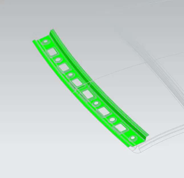
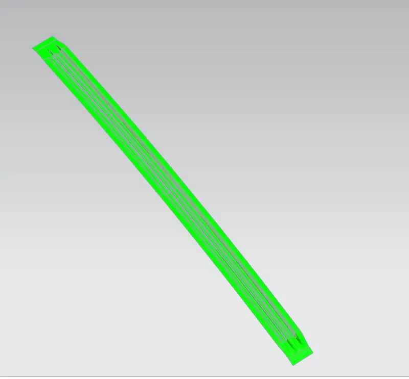
Draft analysis-
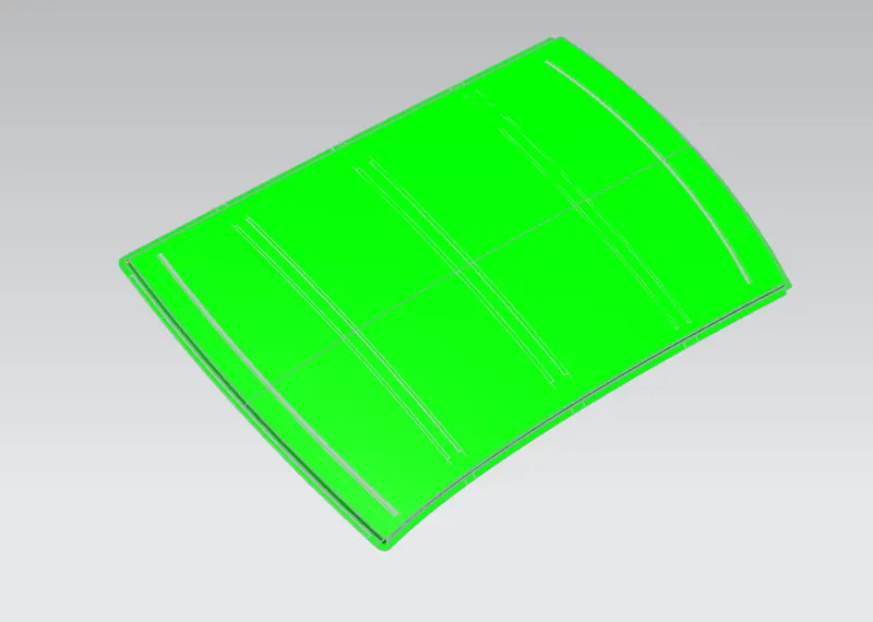
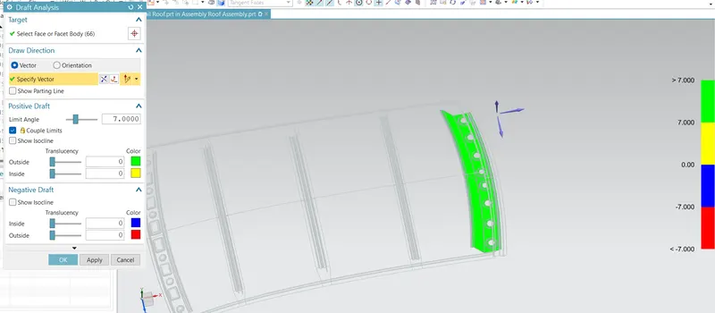
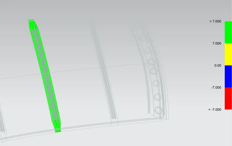
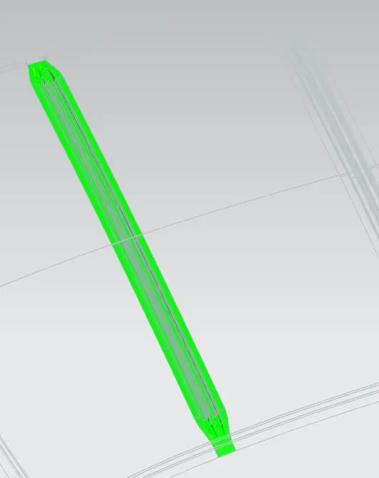
Before we give the part for manufacturing we have to some analysis ourself to check all the constraints and to check if we have any negative draft on a part .
We have a tool called draft analysis in NX Cad to check the following.
Roof
Front roof rail-
Rear roof rail:
Centre Roof
Bow 1
Bow 2
CONCLUSION
I was successfully able to design the roof with all the roof rails for better support and strength and designed it so as to satisfy the norms and regulations by calculating the heat distortion criteria and the snow load critera. While doing this i was also able to understand about the methodology behind designing the roof of the car and what all we take into consideration while designing so.