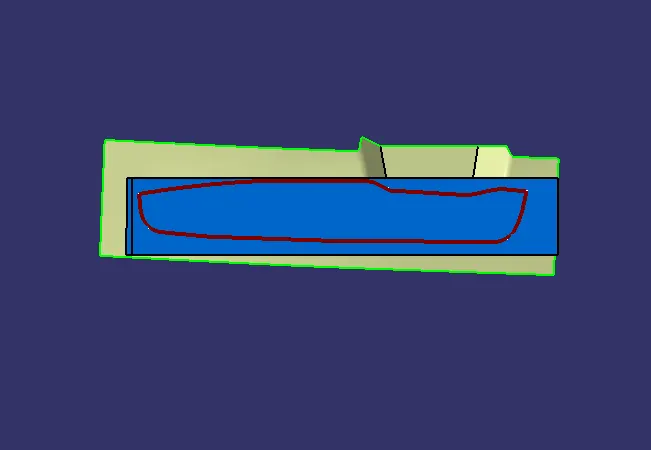
Week 8 - Challenge 6 - Core & Cavity Design
Create the Core and cavity blocks for the switch bezel designed in the earlier challenge.
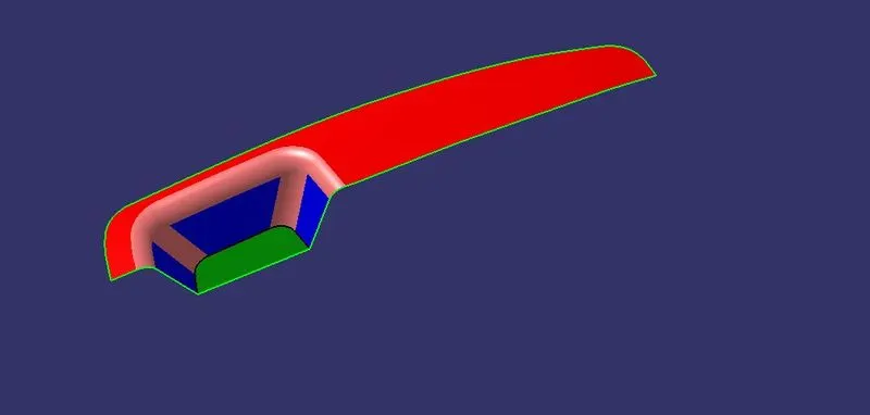
- Screenshots of the Draft analysis report for both the switch bezel plastic component
Before we design the core and cavity, we should perform a draft analysis on the solid part body of the switch bezel.
1.Creating tool axis .
- To create the tooling axis, we need the proper orientation or view that gives the correct features and draft available in the component.
- So here the component view from the Z direction gives the proper view for the tool to see the features present in the geometry.
- Now i Extracted the base surface.
- Center point is created by using the on surface at zero.
- On that point the axis system is created.
- Take an intersection on the YZ plane to get a boundary line.
- Made a dummy axis line to form a tooling axis by a bisecting two lines.
- After that, I switched the surface and made a sketch on the XZ plane.
- Using the axis center point, a line is drawn in sketch mode and it is constrained at the angle of 4 degrees.
- By intersecting both the line so that i get a tooling Axis.
- By using this Tooling i done Draft analysis to the Class A Surface.
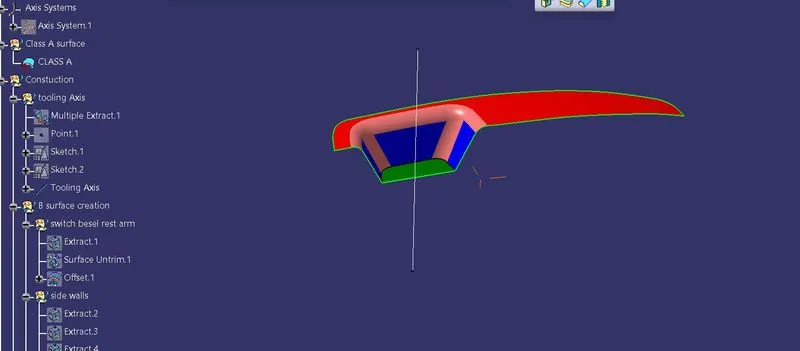
Drafting Class A Surface:
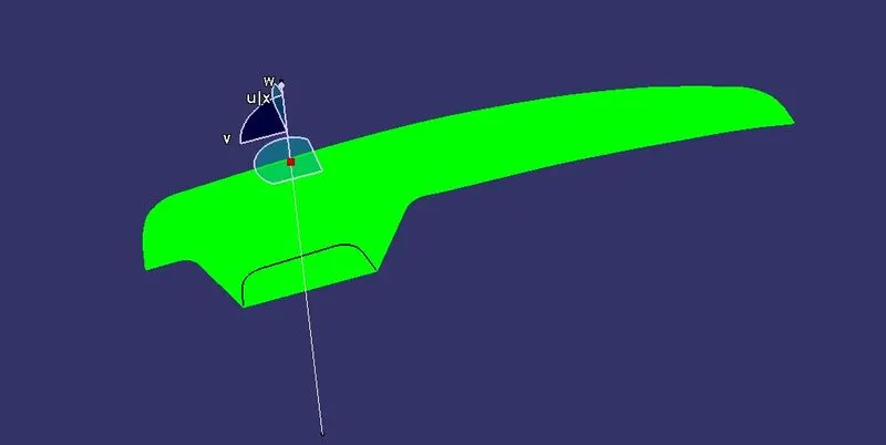
Cretaing the B Surface.
- Base :
- Extract the surface
- Untrim the surface
- Extrapolate it
- Offset it by 2.5mm to the downward.
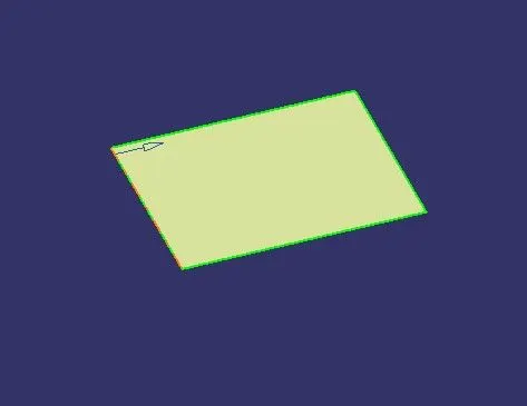
2. Side Walls:
- Extract the three walls separately
- Un-trim the surface of three extracts
- Extrapolate them
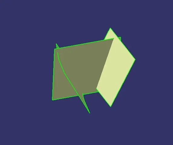
- Trim them with each other.
- Offset the given surface by 2.5mm to the outward direction.
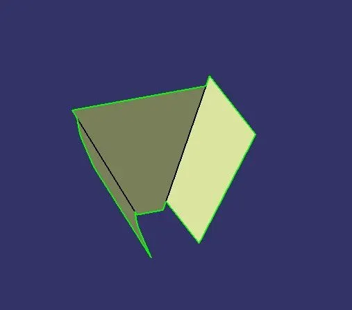
3. Bezel rest surface
- Extract it
- Un-trim the surface
- Extrapolate it
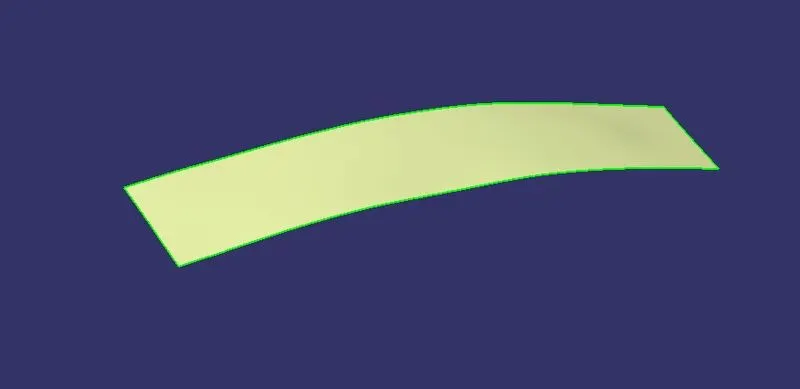
- Offsetted by 2.5mm to the downwards.
So we get all the surface we required then trin all surface so we get calss B surface
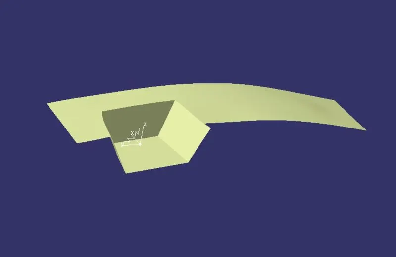
Now we have check the rediues from the class and give fillets to edges then we get results like below image.
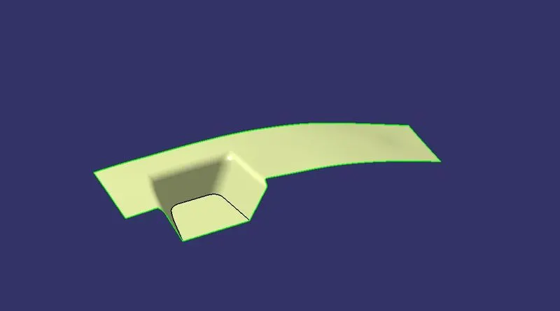
Now this is our B surface
Cretaing the C Surface.
To create the class C surface concerning the boundary of the class A surface, I used the sweep command. Initially, I extracted the boundary of the Class A surface and i used sweep with draft with direction 3 deg(for angle)for 5mm to intersect properly with the class B surface. Once we sweep all the surface boundaries of class A, extrapolate the sweeped surfaces until both surfaces got intersected properly, and trim them to remove extended extrapolated surfaces to get a proper sweep boundary throughout the entire surface, including the centre hole of Switch bazel
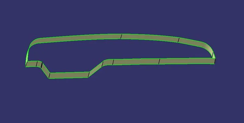
Now, join both class A and sweep boundary to get the complete class C surface
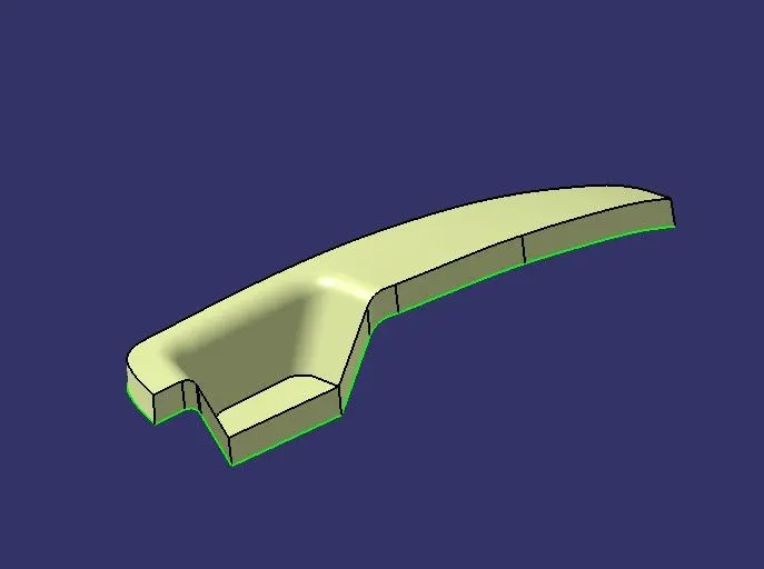
Now, unhide the class B and class C surfaces. Check whether all the sides of class B and Class C surfaces are intersecting properly with each other, to get a closed surface by trimming class B and class C surfaces. If the class B and class C sides are not intersected properly, we need to extrapolate the sides of the class B surface which are not intersecting with the class C surface. Now, check class B and class C surface boundaries whether all the sides are intersecting or not with each other. Once the surfaces are intersecting properly trim them together to get a closed surface.
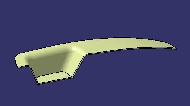
Now we have check the our Bumper fully closed or not by using boundray command.
finally our Bumper is obatained.
Creating a solid body by using a closed surface :
To create soild body firstly switch to part body work bench and use close surface command to soildify the surface body.
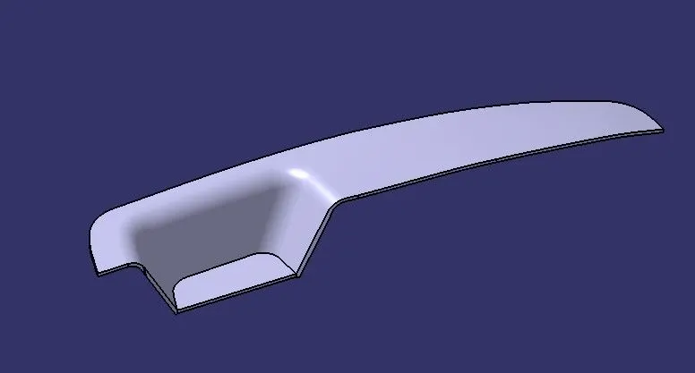
Now we have perform the Drafy analysis on part body
Draft Analysis On Part Body
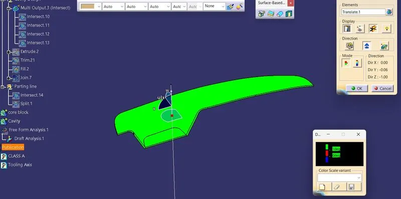
Core and cavity blocks for the switch bezel
- The mold core & cavity are the shaped sections in either half of the mold tool which give the plastic product its final shape.
- The hot molten material is injection into the core & cavity and then sets hard into shape. The design of the core & cavity is essential in the correct formation of the product. The sequence of events during the injection mold of a plastic part is called the injection molding cycle.
- The cycle begins when the mold closes, followed by the injection of the polymer into the mold cavity.
- A core is usually made of the best quality sand and is placed into the desired position in the mold cavity. Core prints are added to both sides of the pattern to create impressions that allow the core to be supported and held at both ends.
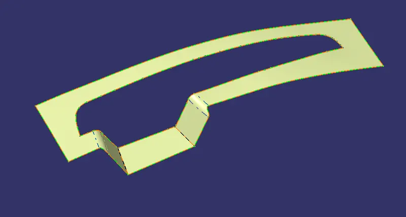
Parting Surface:
- The parting surface of a mold are those surface of both mold plates adjacent to the impressions which butt together to form a seal and prevent the loss of plastic material from the impression.
- Create the boundary line from Class A surface and it Extrapolate up to 20mm.
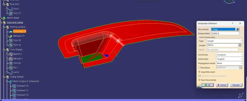
Trim with final trim of sweep in class C surface with explotaaion
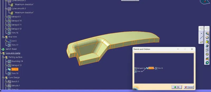
Trim with B surface so that we obtain partig surface
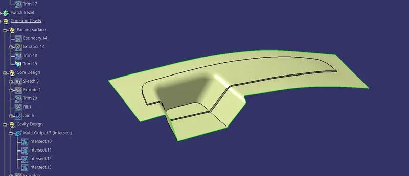
Core Design:
Draw the rectangle Sketch
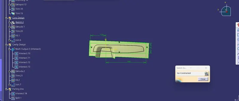
Etrude the sketch
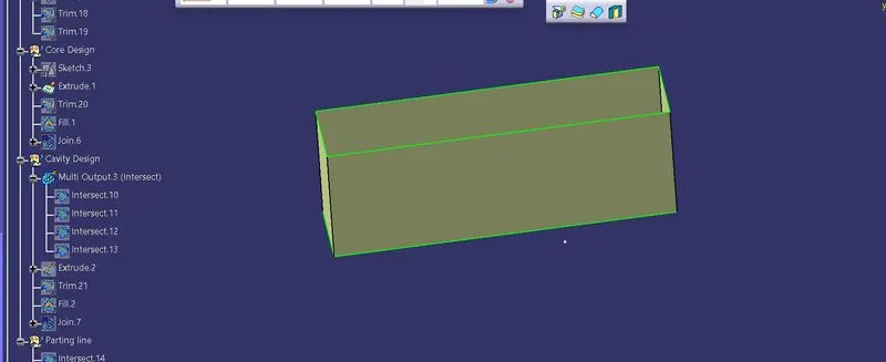
Trim with the partng surface
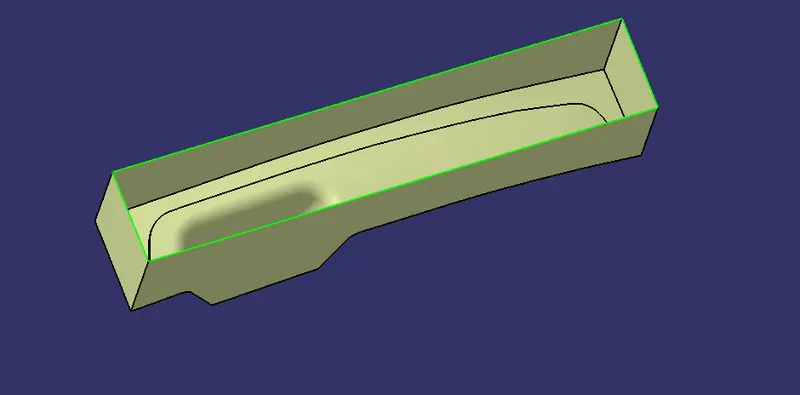
Fill the top surface by using fill command so that top surface is closed
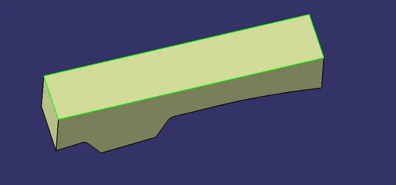
Now join the both surfcaes
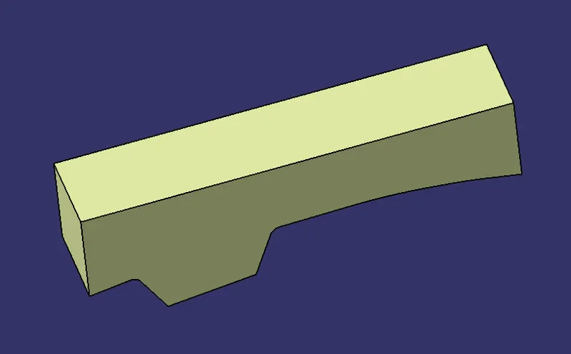
It how core looks and make solidify by using close tool surface based features
so that core is solidify
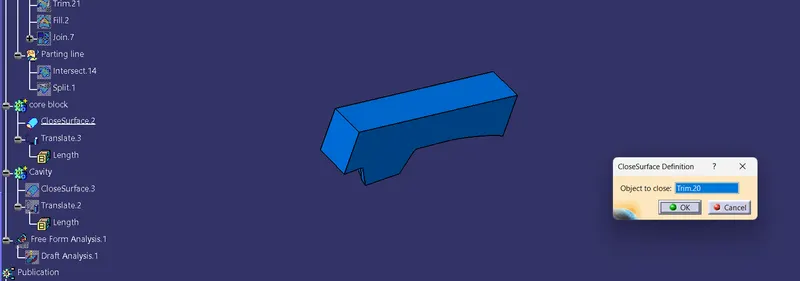
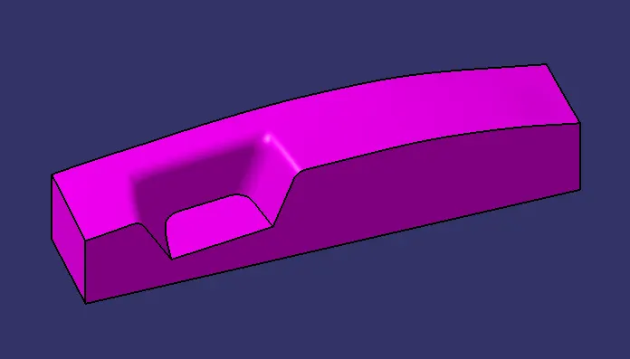
Cavity Design:
- the cavity is the part where the injector and filling of the molten plastic happens. The cavity block is prepared by first extruding the outer boundary along the tooling direction.
- Draw Rectangular profile on Axis system XY plane.
- Extrude the profile along Z direction.
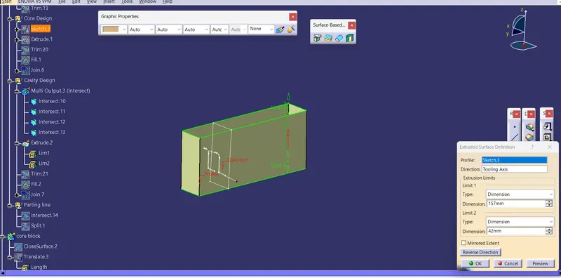
- Trim the surface of Class B surface and extrude.
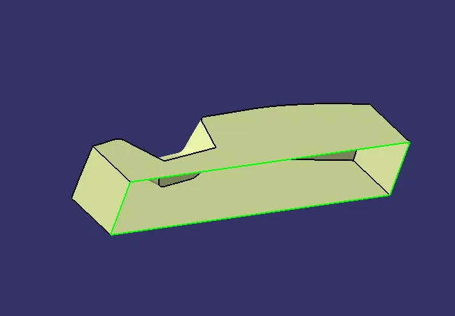
- Fill the top of the surface area.
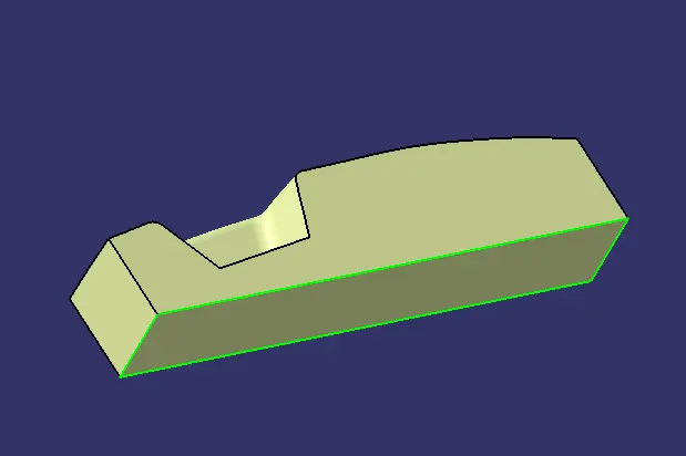
- To join the Fill surface and Trim Surface to get Cavity Design surface model.
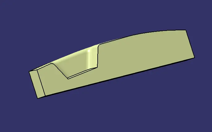
It how Cavity looks and make solidify by using close tool surface based features
so that cavity is solidify
Parting Line:
- A parting line, in industrial casting of molds, is the borderline in which draft angles change direction. That is, it is the dividing line that splits the core and cavity halves of a molded part. It is sometimes a starting point for the mold parting surface.
- To intersect Class B surface class C surface
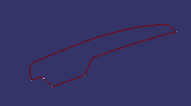
- Trim with thr parting surface
Solid Body:
- The below figure is known as solid body of Core and Cavity Design.
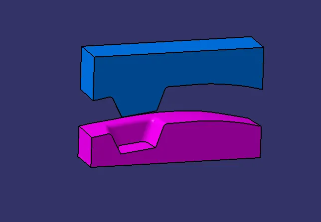
- CORE AND CAVITY DESIGN:
- The below figure is final output of Core and Cavity design.
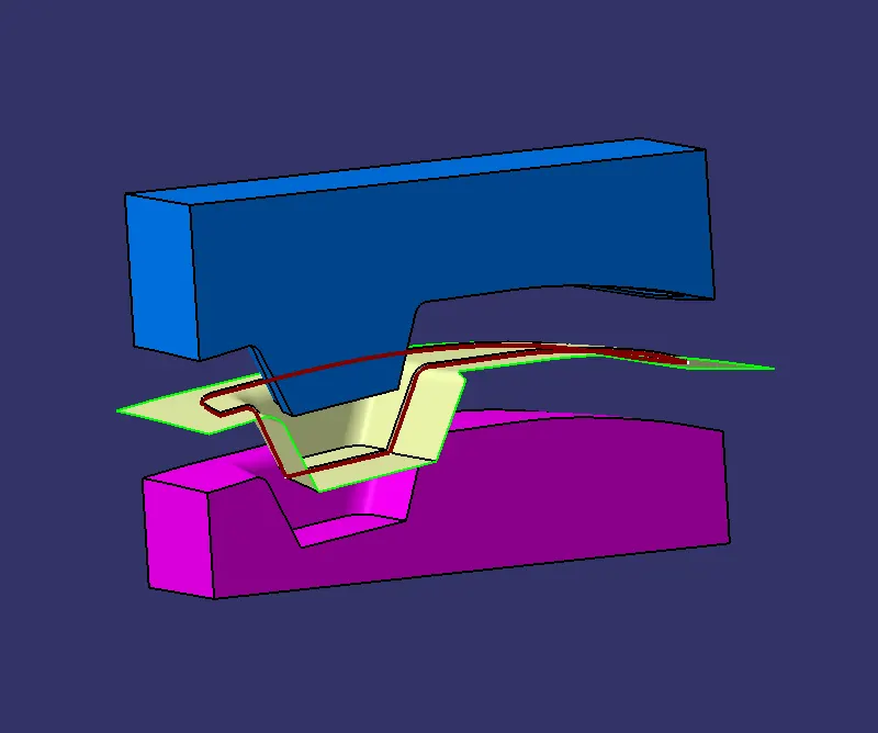
- Screenshots of the core and cavity blocks in various orientations (Isometric, Front, Side, and Top View)
Isometric view
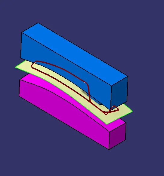
Front view
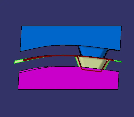
Side view
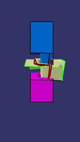
Top View