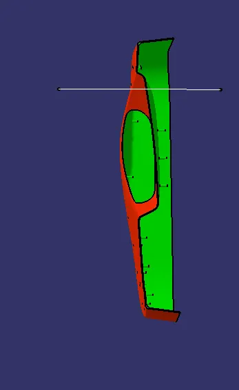
Week 9 - Project 1 - Door Trim Lower with Engineering Features
Create the Door Trim Lower Plastic component through the given Class-A surface. To begin with, the tooling axis for the given Class-A Surface should be created meeting the requirements of the draft angle and at the end perform the Draft analysis on the model.
So that firstly we have to Class A surface as taking as input i.e Door Trim Lower
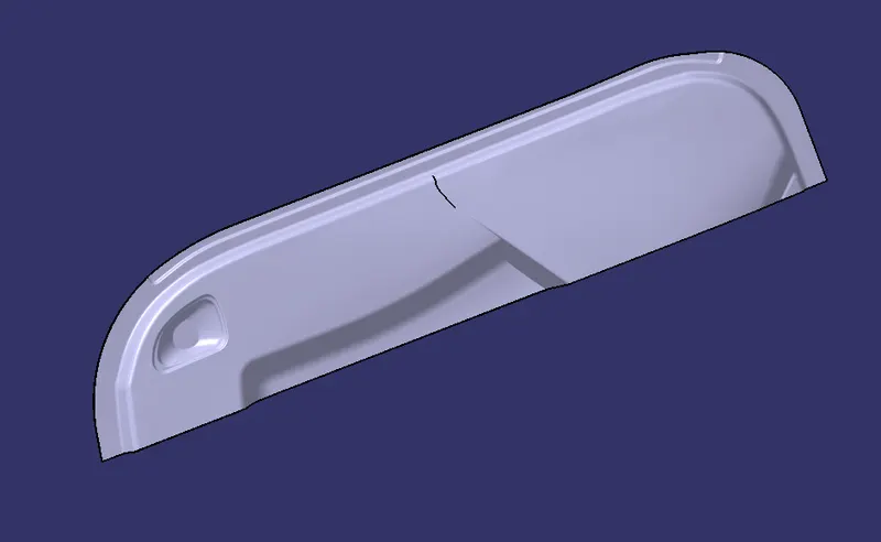
class A surfcae is good there is no patches so we will move further
Next step is Draft Analysis on Class A surface to perform draft analysis on class we have create the tooling axis
Tooling AXis Creation
- First, ensure that the Class-A surface is properly joined and has no discontinuity. Select the boundary command from the toolbars and then select the Class-A surface. A boundary should only appear on the outer edges of the component.
- Then, we decide the proper tooling axis direction with respect to the given component (in this case it is the Y-axis direction).
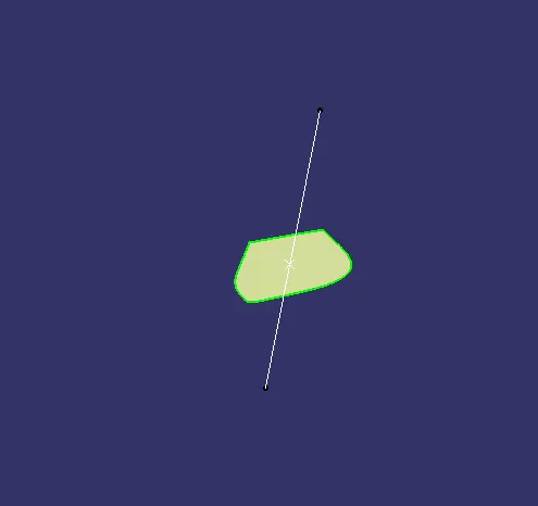
- Generally, the tooling axis is created using bisecting lines method. But in this model, we observe that the side walls are not given any draft. Hence, we assume the axis normal to the base surface and parallel to side walls.
- We create a line normal to base surface by creating a point first on that surface and then create the line using the Normal to Surface method and taking the base surface and the point as references. This new line is considered as the tooling axis.
Drafting Class A Surface:
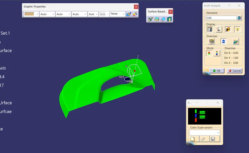
- Go to insert > analysis > feature draft analysis.
- Align the compass with the tooling axis.
- Then, click on the Class-A surface to see if the it is within the permissible limit of the draft values.
- The Class-A surface should turn green and then draft value should be given as 3 degrees.
Cretaing the B Surface.
Now offsetting the class A surface to 2.5mm. while offsetting some tipicaly geometry has not offsettes so we get patches in the surface.
we have clear all the patch by extractig method.
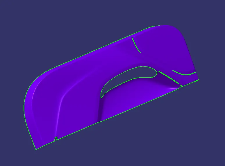
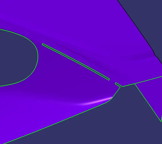
we have all patches from the above image
Patch 1
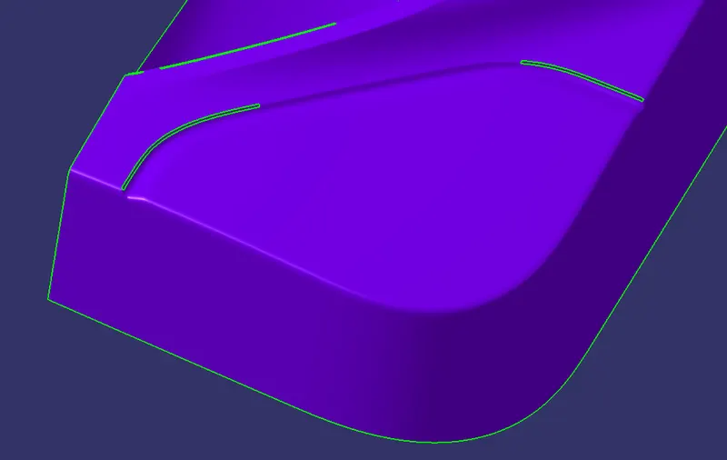
To clear patch i extart alll the required surface and untrim and explotate the surfacee to intersing other surface and make trims
So that i create the surface
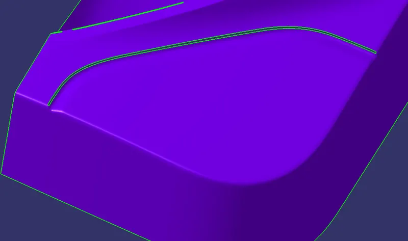
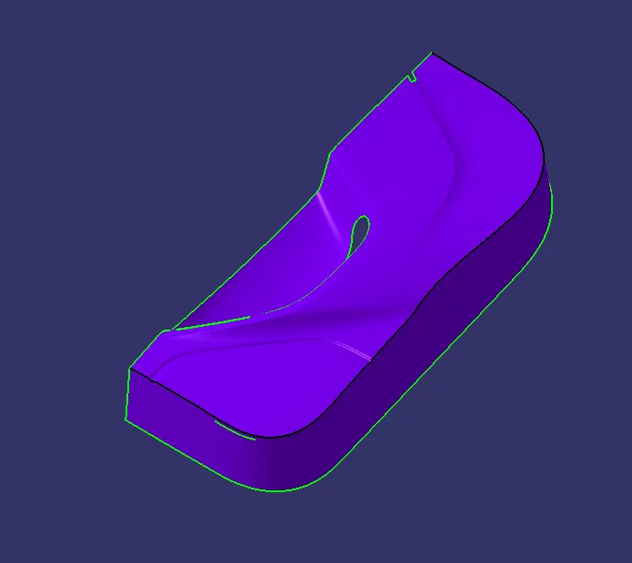
Patch 2
So i split all fillert area in two surface by using multi extract and split command.
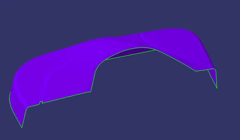
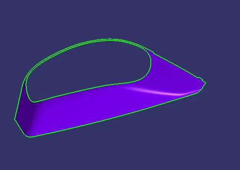
Now explotate the both the surface and trim

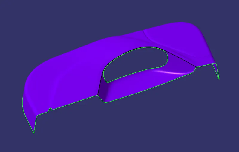
now gave the fillets measure from the class A suface
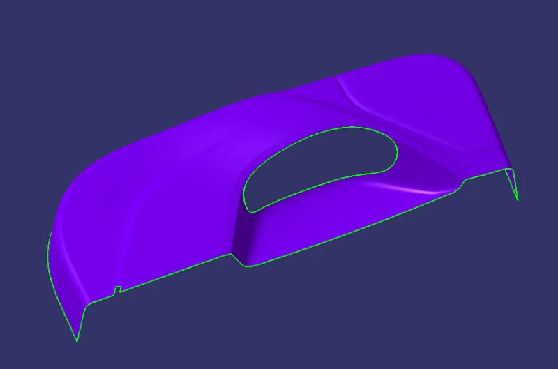
After that we have one patch
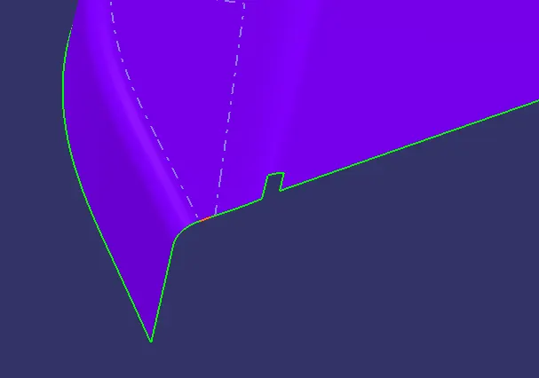
we cleared by using multi section because its fillet area and two parallel surfaces.
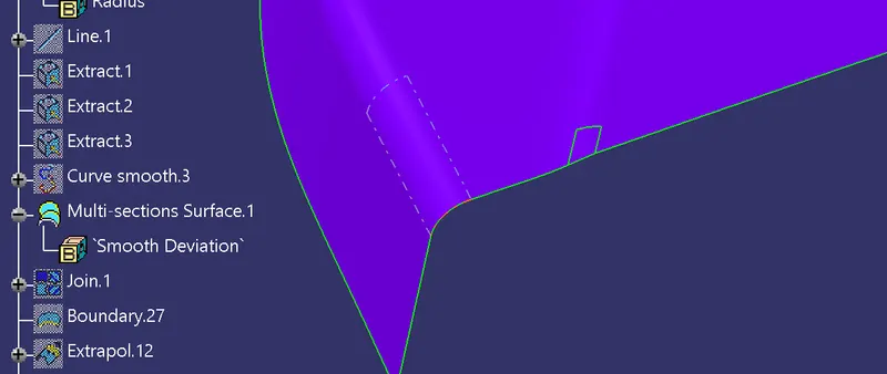
After that join the surface so that we get b surface
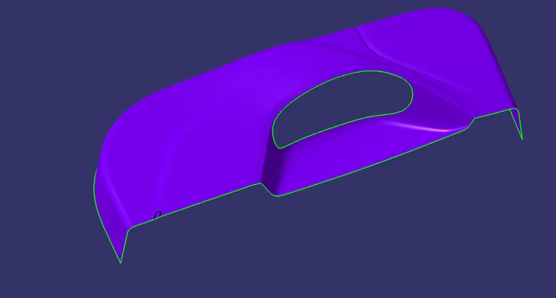
Now our B surface is created.
Cretaing the C Surface.
To create the class C surface concerning the boundary of the class A surface, I used the sweep command. Initially, I extracted the boundary of the class A surface with tangent continuity, and I sweep the extracted boundary concerning the surface at 93deg (for draft angle) for 5mm to intersect properly with the class B surface. Once we sweep all the surface boundaries of class A, extrapolate the sweeped surfaces until both surfaces got intersected properly, and trim them to remove extended extrapolated surfaces to get a proper sweep boundary throughout the entire surface, including the centre hole of the Door Trim lower
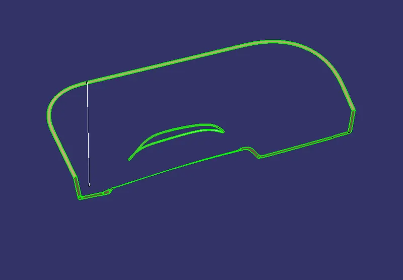
Now, join both class A and sweep boundary to get the complete class C surface
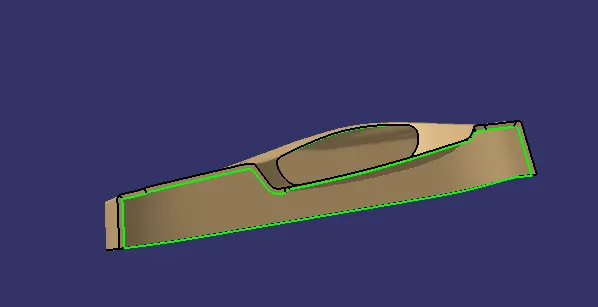
Now, unhide the class B and class C surfaces. Check whether all the sides of class B and Class C surfaces are intersecting properly with each other, to get a closed surface by trimming class B and class C surfaces. If the class B and class C sides are not intersected properly, we need to extrapolate the sides of the class B surface which are not intersecting with the class C surface. Now, check class B and class C surface boundaries whether all the sides are intersecting or not with each other. Once the surfaces are intersecting properly trim them together to get a closed surface.
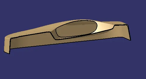
Now we have check the our Door Trim is fully closed or not by using boundray command.
Creating a solid body by using a closed surface :
To create soild body firstly switch to part body work bench and use close surface command to soildify the surface body.
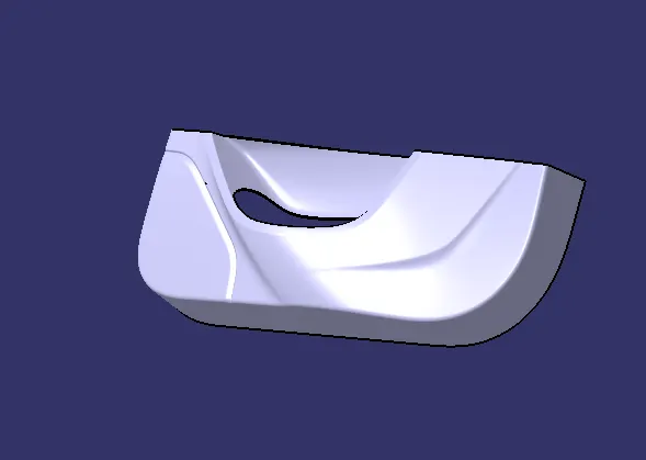
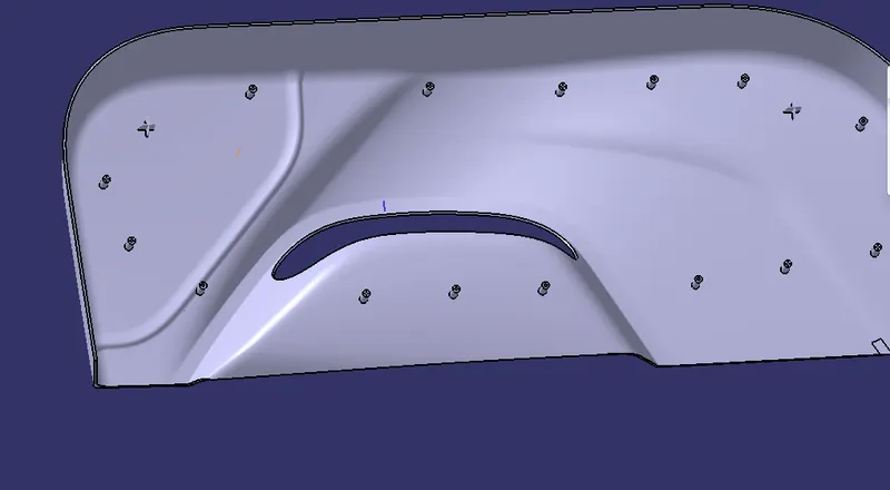 and the locators
Locators:
4 way Locator :4-way mean you prevent movement at 2 axes (+X, -X, +Y and -Y) on the plane.
Firstly extract tha surface and creating a pont on surface and create the plan to create the sketch to 4 way locators
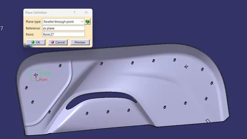
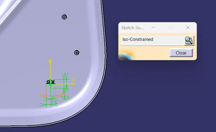
after creating the sketch with proper dimensions as per the standards insert the new body pad the sketch pad and chamfer the four corners with 45 deg angle and draft to 0.5 deg for the walls.
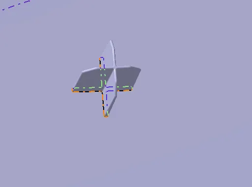
so that four way locator is created and add to the main body
Heat stacks
Manufacturing operations currently use many different combinations of attachment methods to keep components together. Common fasteners such as bolts, screws, and rivets can be used to form permanent attachments, but there are attachment methods that don’t require secondary hardware. One of those methods is heat staking, which doesn’t require additional fasteners.
From the referenc point as in input we have to creat the hest stacks in all the points
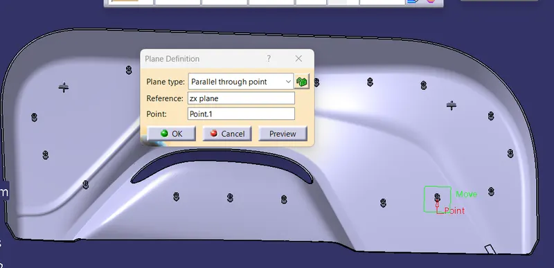
After creating the plas draw the sketch as standards
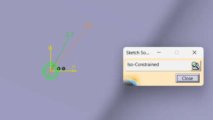
After creatinf the sketch pad it give draft angle both inner and outer walls as 0.5 deg
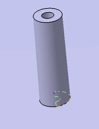
After copy it all points as in the input made assemble to the body add to the main body
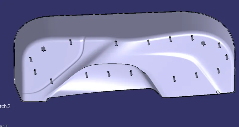
So that heat stacks and locators are created
we have to perfom the draft analyis
Draft Analysis
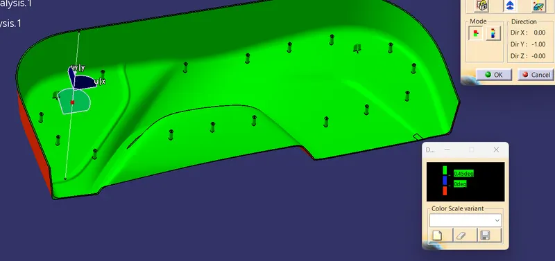
so my heat stacks and locators clearing the draft analysis with 0.45 deg.
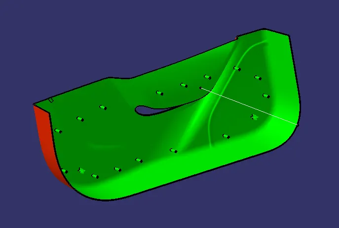
- Screenshots of the completed design in various orientations (Isometric, Front, Side, and Top View)
Isometric View
Front View
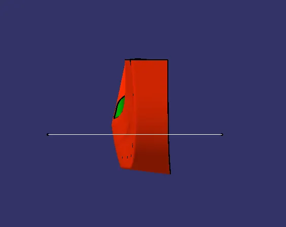
Side View
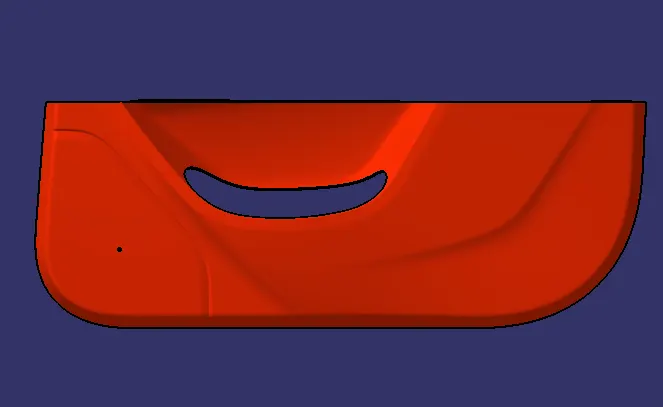
Top View