Wiring harness design in CATIA V5 - 3D modeling Week 4 Challenge
Q1. Route the following harness layout in Electrical workbench. Make assumption for harness bundle diameters. Use Following connectors as shown in layout diagram.
Add protective covering on all branches connected to DT06-2S & DT06-4S connectors. Keep end extremity at 30mm (from connectors end)
Download connector 3D data from www.te.com
- DT06-4S
- DT06-6S
- DT06-2S
- DT06-08SA
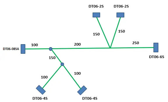
Aim: To route the wiring harness in Electrical Workbench and provide the protective covering to all the branches.
- Firstly, the Connector 3D part file are downloaded from the resource
- Next step is to define the Geometrical parameters of the connectors the required geometrical parameters .
DT06-4S:

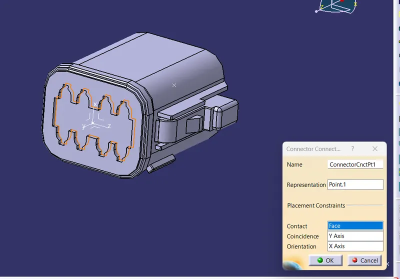
Connector connection point:
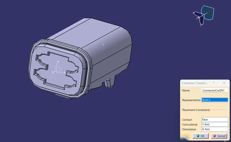
- For creating Connector Connection point, create a point on the contact face which will be normal to the wire bundle insertion.
- Next create an axis system with respect to the point which we have created and defining the axis direction such that the X-axis should be pointing towards the locking mechanism of the connector, the Y-axis should be pointing towards the front face of the connector adn the Z-axis should be pointing across the connector from left to right.
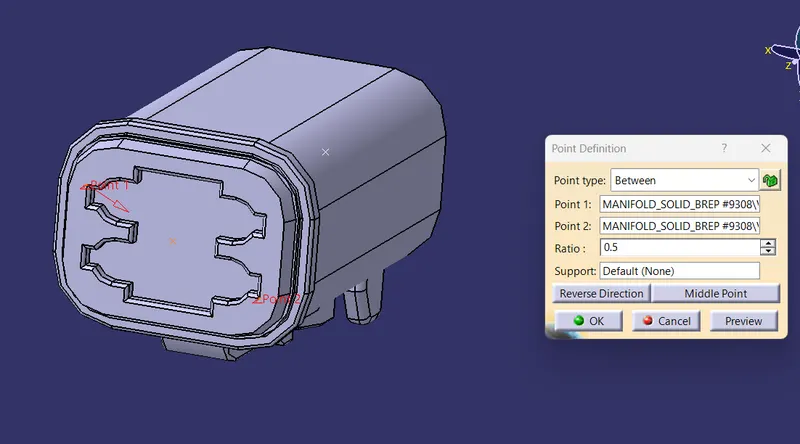
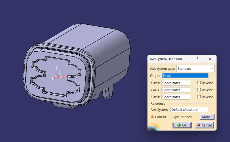
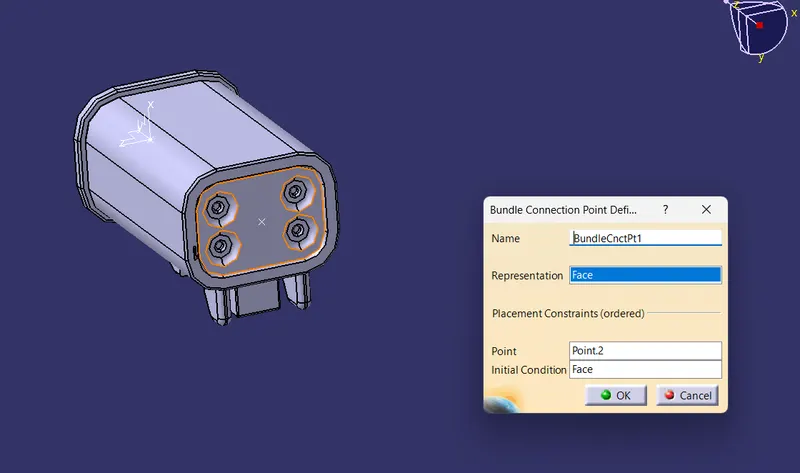
- Further create a bundle connection point on the midpoint of the face.
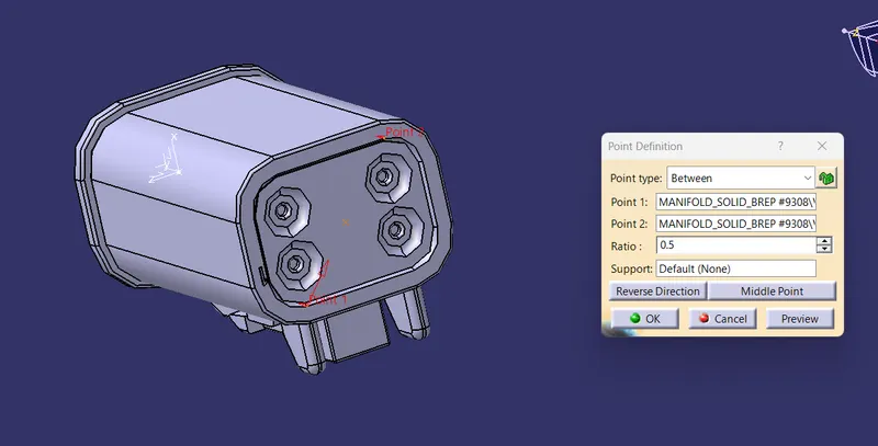
Switch to 'Electric Part Design'
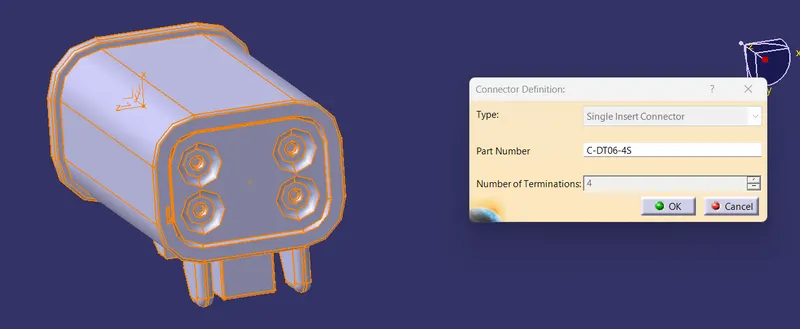
Define the part as connector in catia, give no. of termination as 4 because we have 4 entry points for wire.
Define Bundle connection point
Define connector connection point.
DT06-6S:
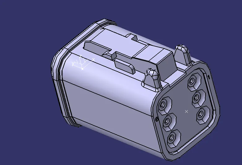
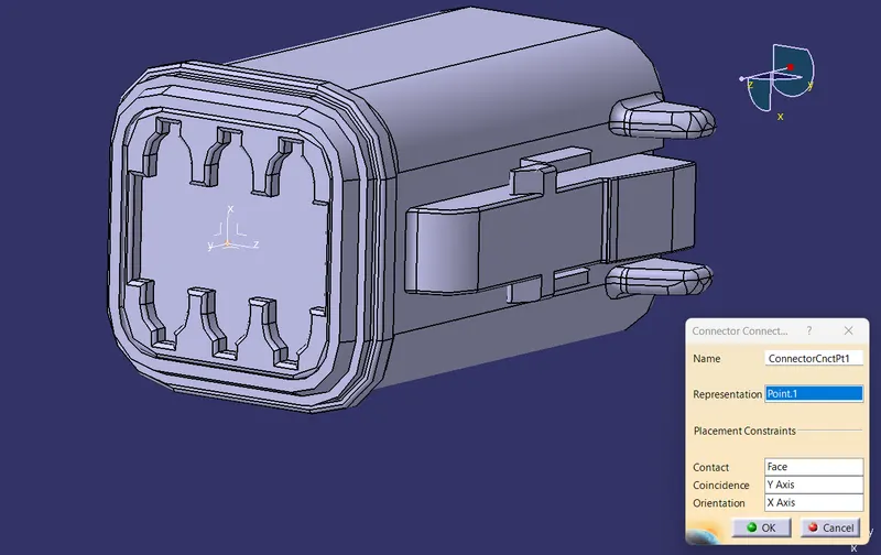
Connector connection point:
- For creating Connector Connection point, create a point on the contact face which will be normal to the wire bundle insertion.
- Next create an axis system with respect to the point which we have created and defining the axis direction such that the X-axis should be pointing towards the locking mechanism of the connector, the Y-axis should be pointing towards the front face of the connector adn the Z-axis should be pointing across the connector from left to right.
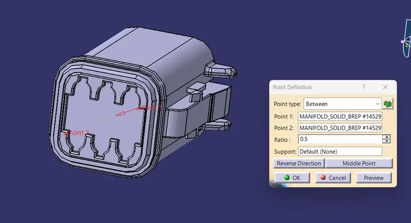
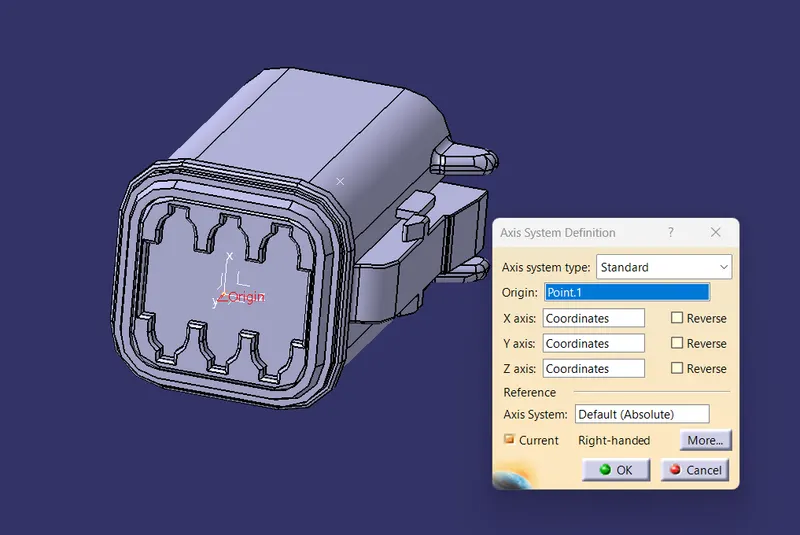
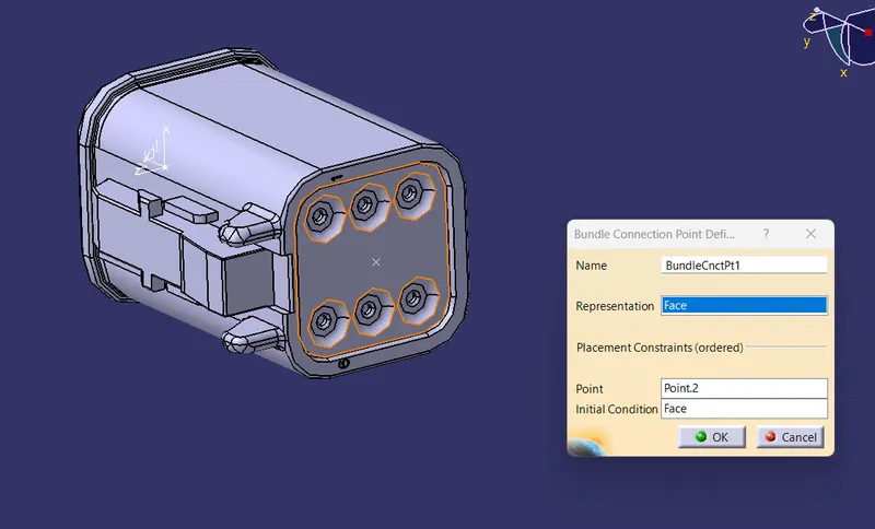
- Further create a bundle connection point on the midpoint of the face.
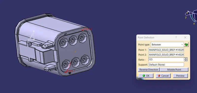
Switch to 'Electric Part Design'
Define the part as connector in catia, give no. of termination as 6 because we have 6 entry points for wire.
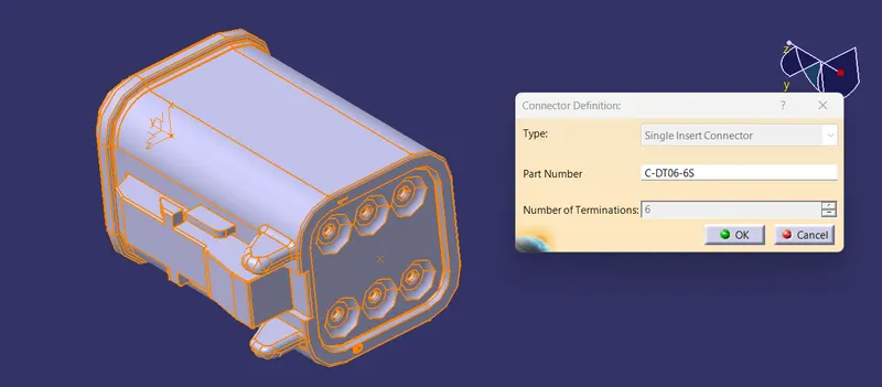
Define Bundle connection point
Define connector connection point.
- DT06-2S
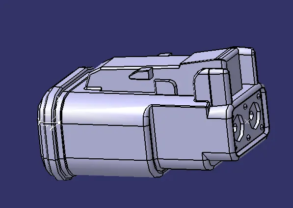
Connector connection point:
- For creating Connector Connection point, create a point on the contact face which will be normal to the wire bundle insertion.
- Next create an axis system with respect to the point which we have created and defining the axis direction such that the X-axis should be pointing towards the locking mechanism of the connector, the Y-axis should be pointing towards the front face of the connector adn the Z-axis should be pointing across the connector from left to right.
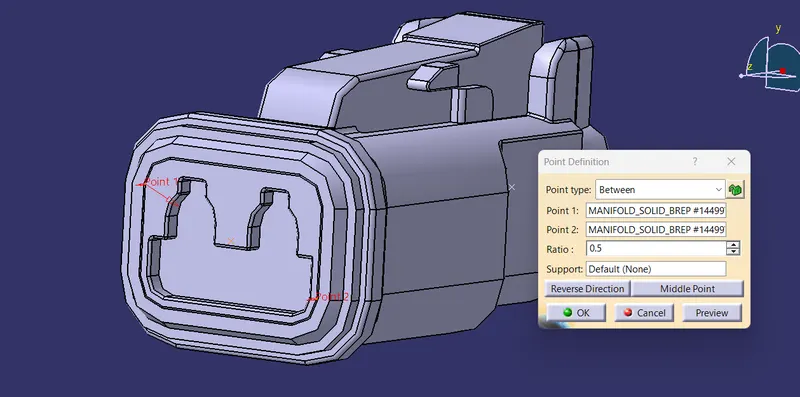
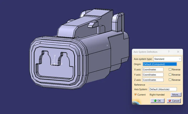
- Further create a bundle connection point on the midpoint of the face.
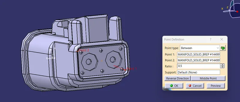
Switch to 'Electric Part Design'
Define the part as connector in catia, give no. of termination as 2 because we have 2 entry points for wire.
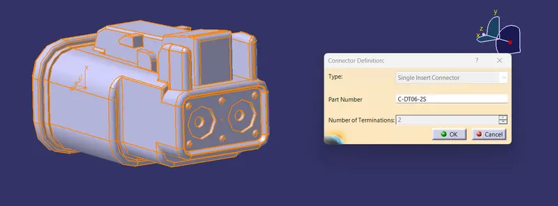
Define Bundle connection point
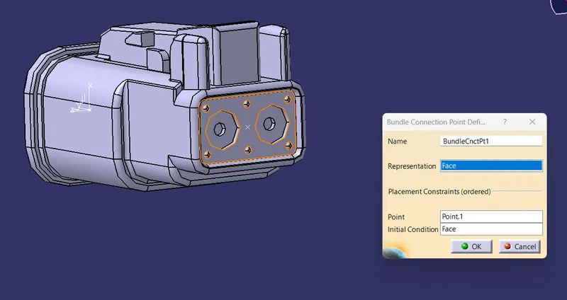
Define connector connection point.
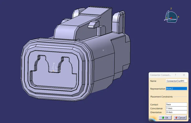
- DT06-08SA
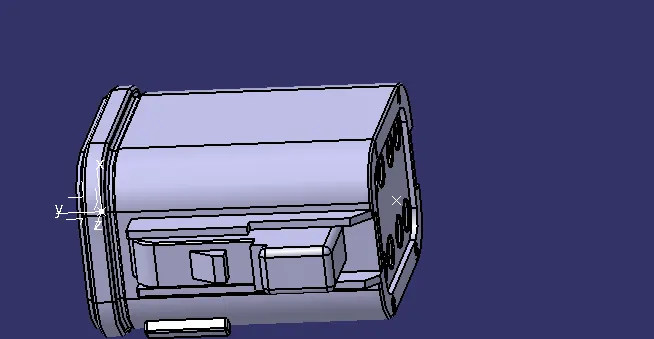
Connector connection point:
- For creating Connector Connection point, create a point on the contact face which will be normal to the wire bundle insertion.
- Next create an axis system with respect to the point which we have created and defining the axis direction such that the X-axis should be pointing towards the locking mechanism of the connector, the Y-axis should be pointing towards the front face of the connector adn the Z-axis should be pointing across the connector from left to right.
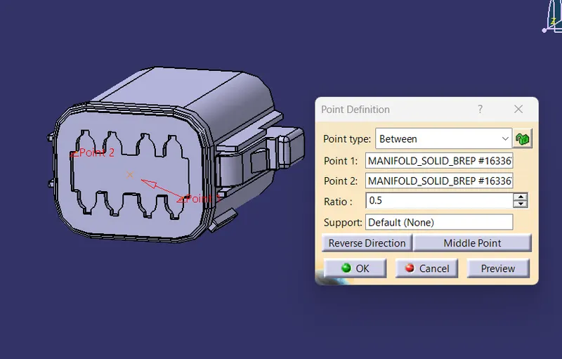
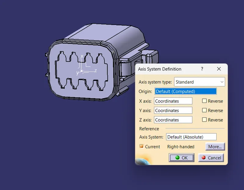
- Further create a bundle connection point on the midpoint of the face.
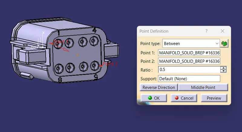
Switch to 'Electric Part Design'
Define the part as connector in catia, give no. of termination as 8 because we have 8 entry points for wire.
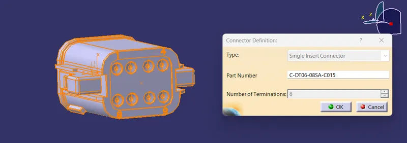
Define Bundle connection point
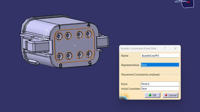
Define connector connection point.
After defining the componenets of Wiring Harness next we must prepare the Product assembly for the given harnes.
Wiring Harness Product Assembly
- Create a new product file
- Insert all the required Surrounding Part data into the Product file.
- Save the master product file in a desired location.
- Select the "Geometrical Bundle" command and then click on Product Icon in Model tree to convert it into an Electrical Assembly
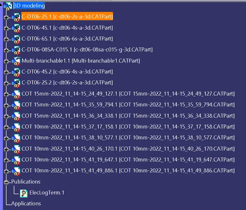
Affter that all the connector has arrange according to the below image by using Sanp,manipulation .. etc to arrange to desire location.
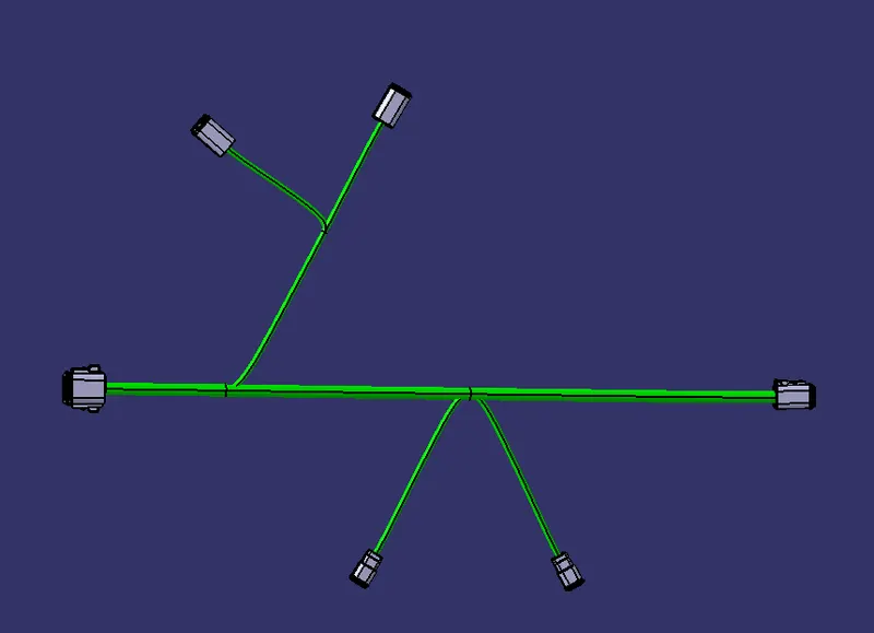
now all the connector to desire location.
useing multibrance Document command use define the branch defination of bundle segments of each connetor.
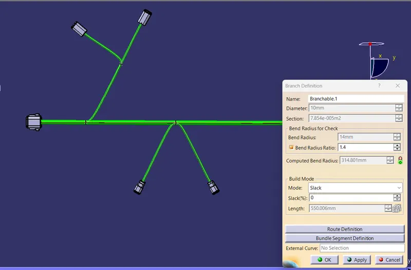
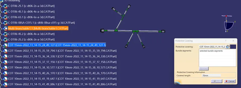
next protective covering on all branches connected to DT06-2S & DT06-4S connectors.
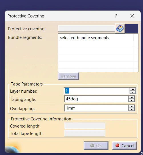
In electrical Harness assembly we have command protective cover.
if we click in protective Covering command
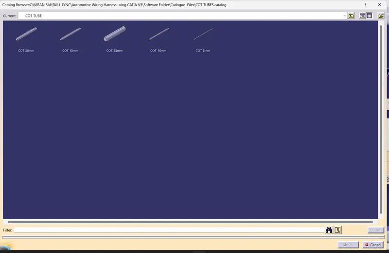
From the above catlog we have to choose requires diameter Catlog.