Week -2
Q1. Making of Simlink model of Door bell using Solenoid block.
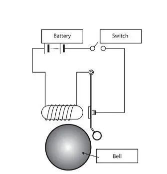
- In the Above arrangement which the switch is closed the electromagnet receives electrical power from the battery and pulls the metal arm to hit in the bell produceing the sound.
- Here i'm creating the to switch is closed for 2 second and then release movement of the plunger.
- Assume remaining parameters
Explanisation for the doorbell circuit:
- The circuit of the door bell using the solenoid block as shown in fig
- when we close the switch we complete the circuit then the electric current id flow tgrough the circuit.
- After that,the electromagnet get charged,and then it acts like a magnet due to which it pulls the near metal chip towards to it.
- As a metal clip move towards the magnet the extended part of the meatal clip hits the gong and create the sound.
Following is the simulation model for the door bell using a solenoid block.
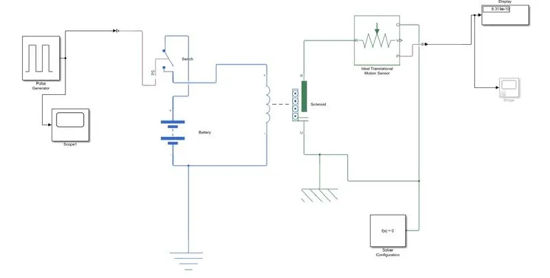
The purpose of simulation blocks used are follows:
1. Pluse Generator : The Pluse genertor block generates Square wave pluse at regular intervals. The block waveform parameters,amplitude,plusewidth,period,and phase dealy determine the shape of the output waveform.
2.Scope : Display signals generated during simulation.
3.Simlink-PS-converter: Converts the simlink inputs to physical signal.
4.SPST: The block represents a signal-pole-signal -throw switch controlled by an external control signal vT. If vT greter than the threshold,then the switch is open.
5.Battery : It is started elctrical reference block represents an electrical ground.
6.Soloenoid: The Solenoid block represents the lectrical charaterisics and generate force for the solenoid. This solonoid block represents port R move represents move towards port c.
7. Mechanical Translational reference : it is block represents a reference point ,or frame for all mechanical translational ports.
8.Solver Configuration : It is block Specifies the solver paremeter that your model need before you can begin the simulation.
9.Ideal motion Translational sensor: It acts as a motion sensor in mechanical translational system. And this block represents a device that converts an across variable mesures between two mechanical translational nodes into a control signal proportional to velocity .
10.PS-Simlink converter: it converts the input physical signal to a simlink output signal
Working of Door bell simulation.
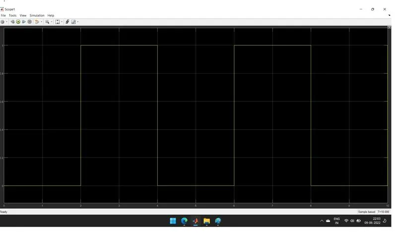
1.Pluse Generator creates an ionput signal of pluse with 1 unit amplitude,4sec period,having 50% pluse width with 2- sec dealy for the model.
2.Then we attach the scope to get so that we can compare the input and outputs of the model.
3. Now the input signal is connected to the simlink-Ps-converter which converts the simlink signal to a physical signal which is then sent towards the SPST switch.
4.After receiving the physical signal,the SPST switch compares it with its threshold valve if it grater than it, then it close the electric circuit,or else it is open.
5.After the electrical circuit is closed flow the circuit is flown from the circuit and then it energies the solenoid connected to the bettery.
6.As the solenoid is charged it pull the port R towardsport C
7.A mechinical translational reference is attached to the port R f the soloenoid to understand the postion of velocity of the plunger to the solenoid.
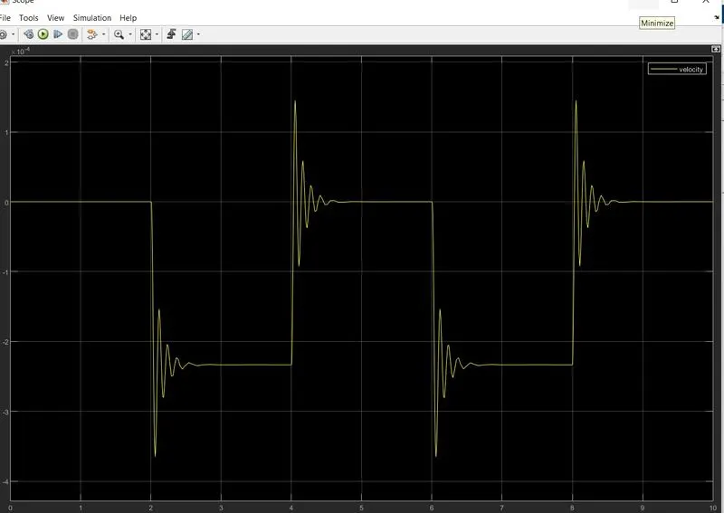
8.To record its postion and velocity Ps-converter that physical signal to a simlink signal and then using the scope block we record it for the simulation duration.
Results.
Q2. Use a thermistor to sense the temperature of a heater & turn on or off the fan as per the below conditions:
- Temperature source: 20 Deg.C from 0 to 10 seconds, 27 Deg.C from 10 to 30 seconds =, 23 Deg.C from 30 to 50 seconds.
- Fan conditions: On if the temperature above 25 Deg.C, OFF otherwise
Sol.
Theory
- A thermistor is a type of resistor whose resistance is strongly dependent on temperature, more so than in standard resistors. The word is a combination of thremal and resistor.Thermistors are widely used as inrush current limiters,temperature sensors (negative temperature coefficient or NTC type typically),self -resetting overcurrent protectors,and self-regulating heating elements (positive temperature coefficient or PTC type typically).
- Thermistors are of two opposite fundamental type:
- With NTC theermistors,resistance decreases as temperature rises usually due to an increase in conduction electrons bumped by thermal agiation from the valency band. An NTC is commonly used as a temperature sensor, or in series with a circuit as an inrush current limiter.
- With PTC thermistors,resistance increases as temperature rises usually due to increased thermal lattice agitations particurally those of impurities and imperfections. PTC thermistors are commonly installed in series with a circuit and used to protect agaiinst overcurrent conditions,as resettable fuses.
- Thermistors are of two opposite fundamental type:
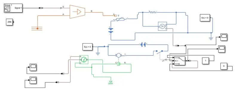
- In the above model the simulation blocks used & their purpose are as follows:
- Controlled temperature Source - The Controlled Temperature Source blocks represents an ideal source of thermal energy that is powerful enough to maintain specified temperature differneces across the source regardless of the heat flow consumed by the system.
- Thermistor - The Thermistor block represents an NTC thermistor using the B-parameter equation.The resistance at temperature at temperature T is R=
- Resistor - The Resistor blocks represents a linear resistor.
- Voltage Sensor - The Voltage Sensor block represents an ideal voltage sensor, that is, a device that converts voltage measured between two points of an electrical circuit into a physical signal proportional to the voltage.
- Battery - The Battery block represents a simple battery model.
- Electrical Reference - The Electrical Reference block represents an electrical ground.
- Unniversal Motor - The Universal Motor block represents the electrical and torque characterstics of a universal (or series) motor.
- Mechanical Rotational Reference - The Mechanical Rotational Reference block represents a reference point or frame, for sll mechanical rotational ports.
- Ideal Rotational Motion Sensor - The ideal Rotational Motion Sensor blocks represents an ideal mechanical rotational motion sensor, that is ,a device that converts an across variable measured between two mechanical rotational nodes into a control signal proportional to angular velocity ar angle.
- Solver Configuration - The Solver Configuration block specifies the solver parameters that your model needs befor you can begin the simulation.
- PS-Simulink Converter - Converters the input Physical Signal to a Simulink output signal.
- Scope - Display signals generated during simulation.
- Working of signal builder block
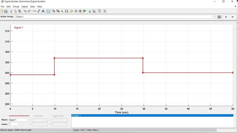
from 0-10 sec themperture is 293.15 k
from 10-30 sec temperture is 300.15 k
from 30-50 sec temperure is 296.15 k
- Working of the Model.
- The temperature source subsystem model provides the temperature to the controlled Temperatured Source,according to the inputs it provides the surrounding temperature condition to the thermostat.
- The thermostat is connected in a closed circuit with a battery and a resistor connected in a series combination with it.
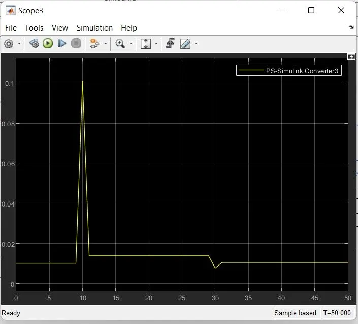
- As the temperature increases the thermostat resistance value decreases and the overall current in the circuit increases, which leads to an increase in the voltage around the resistor of 10 ohms.
- We note the Voltage around the resistor when the temperature is about 25 Deg.C which is 2.273V
- By using the PS-Simulink converter a physical signal from the voltage sensor into a Simulink signal and record it using a scope block to understand how voltage varies with the temperature.
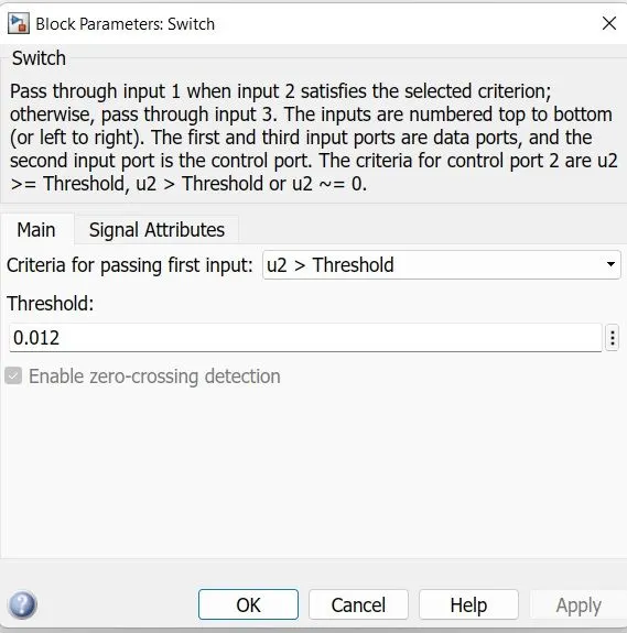
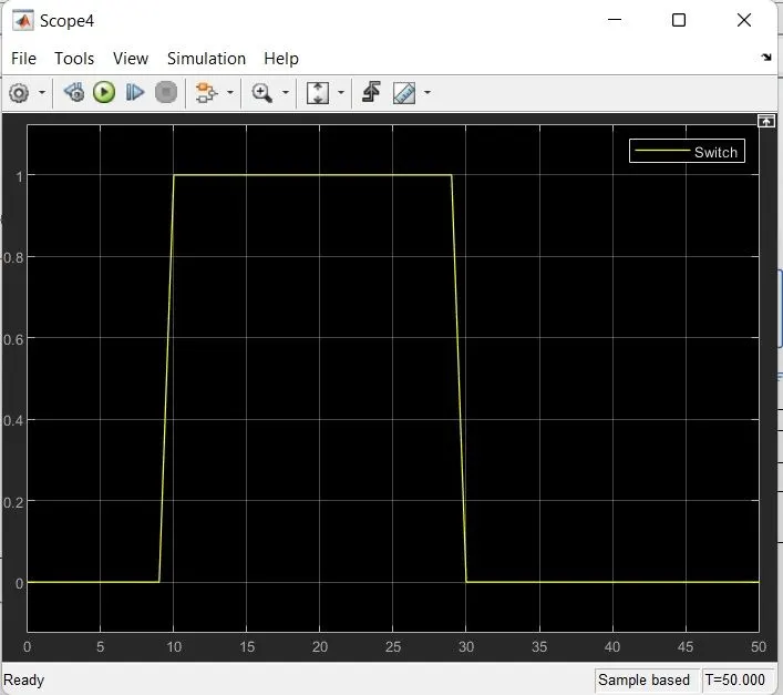
- The Voltage sensor signal is also sent to SPST whose threshold value is 2.273V,i.e. when the temperature goes above 25 degreee celcis the SPST switch is closed & completes the circuit.
- As the universal motor is connected in series with the SPST switch and to the battery, it gets on only when the temperature is above 25 Deg.C
- To verify the outcome of the unnivesal motor we have attached the ideal Rotational Motion Sensor to it.
- Now the PS-Simulink convertes the physical Signal from the rotational sensor and converts it into a simulink signal which is then used to record the angular velocity and angle of the universal Motor
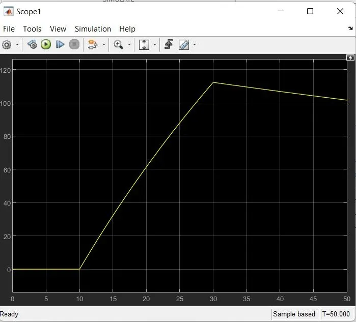
Result:
Conclusion
- We have completed and run the model of the doorbell using a solenoid block.
- Thus Bell is rung for every alternate 2 seconds.
- We have completed and run the model of using a thermistor to sense the temperature of a heater & turn on or turn off the fan aas per condition.
- Thus Fanis Turned on noly when the temperature is above 25 Deg.C.
- We observe the little spike in voltage vs time pplot of the resistor, its because we use the same battery source for the motor allso since the motor is turned on and off only when the temperature is above or below 25 Deg.C respectively these spikes can only observe during that changed.