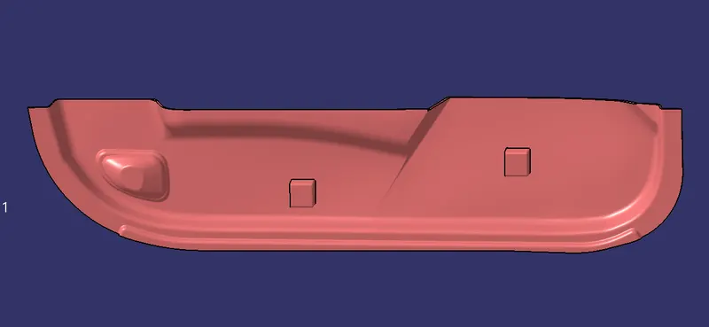
Week 9 - Attachment Feature Creation - Challenge 2
Create the Dog House for the Door Trim considering the design rules mentioned in the video. Consider the thickness of the part to be 2.5 mm.
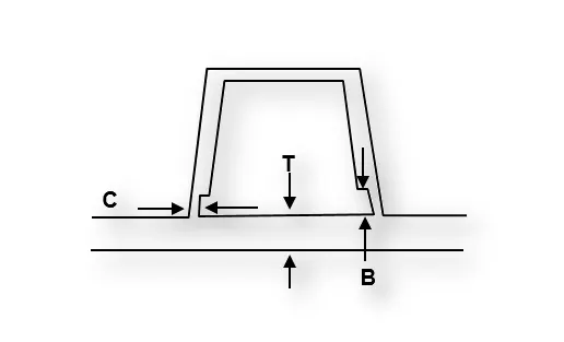
"C" is where the doghouse contacts the backside of the surface
-
Doghouse wall thickness at the intersection of the part wall ( C ) should be 40% or less than the main wall stock ( T ).
-
The height of ( B ) should be between 3.0 – 6.0 mm
To Create the dog house in Door Trim with thinkness 2.5mm firstly we have to Class A,Class B,Class C surfaces and did draft analysis after that with standards is shown above we willl craet the dog house.
So that firstly we have to Class A surface as taking as input i.e Door Trim
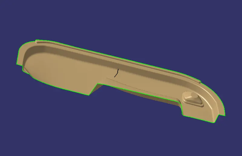
class A surfcae is good there is no patches so we will move further
Next step is Draft Analysis on Class A surface to perform draft analysis on class we have create the tooling axis
Tooling AXis Creation
- EXtract flat surface and create a point the surface.
- Creat a ponit on surfcae
- By instrecting tool interst the point with the class A surface
- Now we have interction .
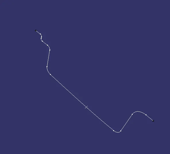
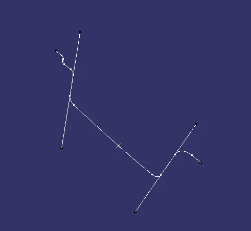
- By takeing line bisecting method we get the tooling axis
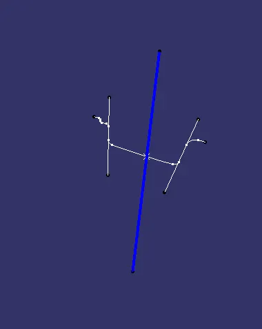
- NOw the cooing Axis is created
- Perform the draft analysis on Class A surface
Draft Analysis on Class A surface
- Go to insert > analysis > feature draft analysis.
- Align the compass with the tooling axis.
- Then, click on the Class-A surface to see if the it is within the permissible limit of the draft values.
- The Class-A surface should turn green and then draft value should be given as 3 degrees..
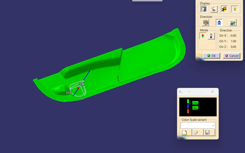
Creating Class B Surface:
Now offsetting the class A surface to 2.5mm. while offsetting some tipicaly geometry has not offsettes so we get patches in the surface.
we have clear all the patch by extractig method
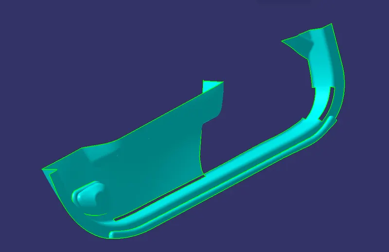
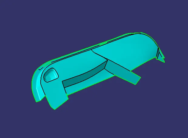
we have all patches from the above image
Patch 1
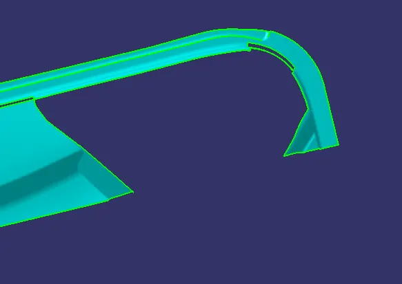
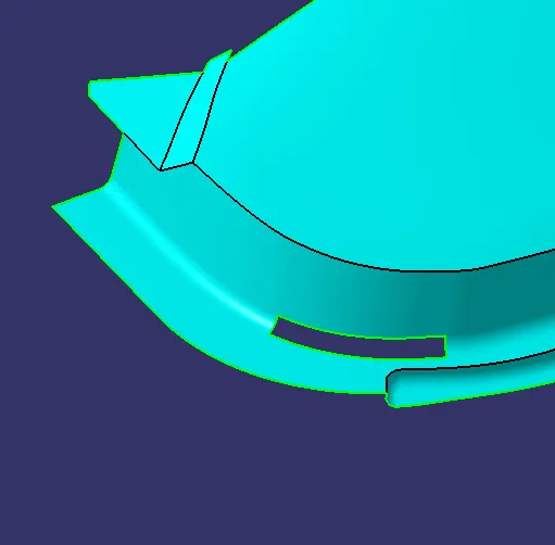
To clear patch i extart alll the required surface and untrim and explotate the surfacee to intersing other surface and make trims
So that i create the surface
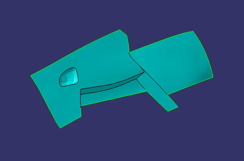
After that i split the surface i.e side walls
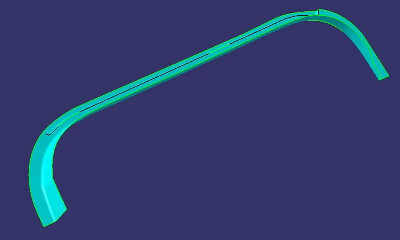
Afert i explotate the surface
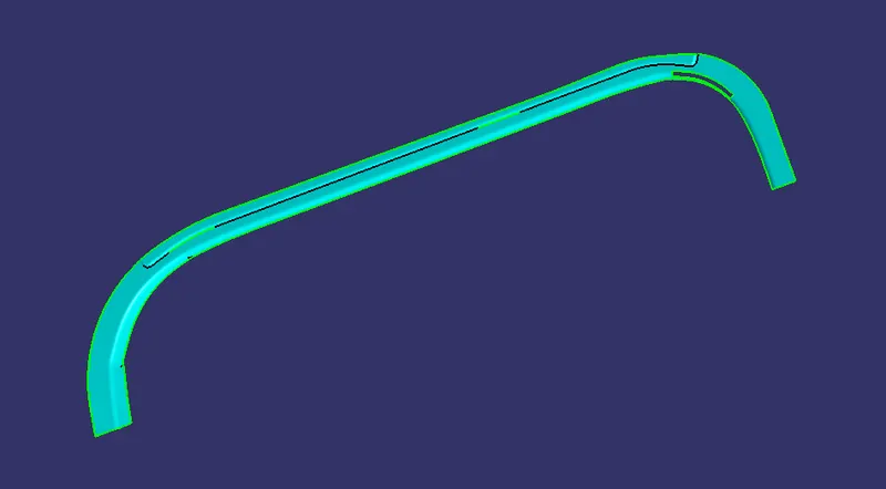
so that i explotate the surface to interset eact other trim both surface
After that i have one patch
so i did the same remove the total fillert by multi extract in complementarty mode
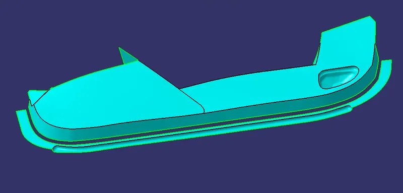
After that exploate the both the surface ti intersect each other and trim
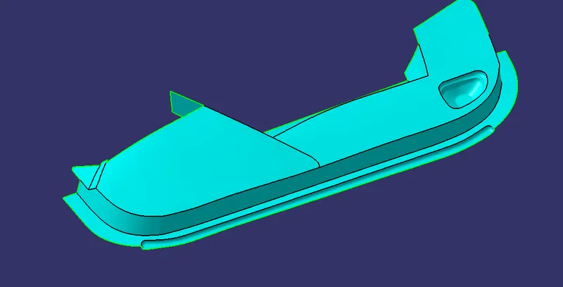
now i gave all the required fillets
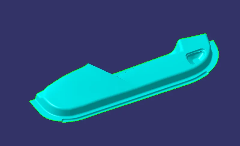
So that our class B surface is obtained.
Cretaing the C Surface.
To create the class C surface concerning the boundary of the class A surface, I used the sweep command. Initially, I extracted the boundary of the class A surface with tangent continuity, and I sweep the extracted boundary concerning the surface at 93deg (for draft angle) for 5mm to intersect properly with the class B surface. Once we sweep all the surface boundaries of class A, extrapolate the sweeped surfaces until both surfaces got intersected properly, and trim them to remove extended extrapolated surfaces to get a proper sweep boundary throughout the entire surface, including the centre hole of the door trim
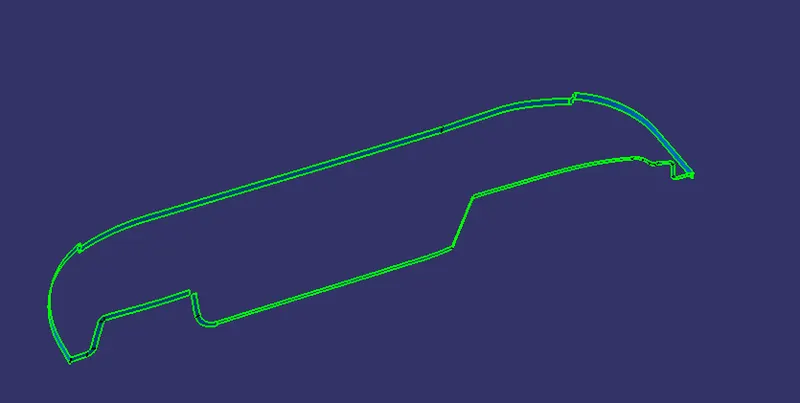
Now i joine with Class A surface
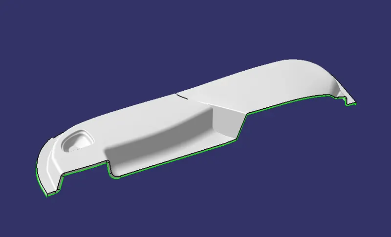
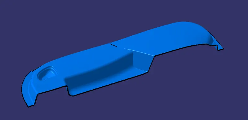
Now, unhide the class B and class C surfaces. Check whether all the sides of class B and Class C surfaces are intersecting properly with each other, to get a closed surface by trimming class B and class C surfaces. If the class B and class C sides are not intersected properly, we need to extrapolate the sides of the class B surface which are not intersecting with the class C surface. Now, check class B and class C surface boundaries whether all the sides are intersecting or not with each other. Once the surfaces are intersecting properly trim them together to get a closed surface.
 .
.
Now we have check the our Bumper fully closed or not by using boundray command.
finally our Door Trim is obatained.
Creating a solid body by using a closed surface :
To create soild body firstly switch to part body work bench and use close surface command to soildify the surface body
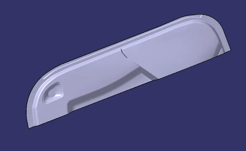
So our part is created no we weill creaet B side feature that dog house on part body
Dog House Creation
Dog house is an engineering feature used in plastic trim design. Dog houses are used as supporting feature. Sometimes other engineering features like snaps; locators etc. are mounded on them to increase their strength. Dog houses are subjected to draft analysis to prevent breakage of the component during ejection from mould cavity.
DESIGN CONSIDERATION FOR PLASTICS:
1.WALL THICKNESS:
Thick sections waste material and are simply uneconomic. So solid shapes that would do the job well in wood or metal must be transformed to a 'shell' form in plastics. This is done by hollowing out or 'coring' thick parts so you are left with a component which regardless of complexity is composed essentially of relatively thin walls joined by curves, angles, corners, ribs, steps and offsets. As far as possible, all these walls should be the same thickness. Wall thickness guide range is 0.75 mm to 3 mm for reinforced materials 0.5 mm to 5 mm for unreinforced materials.
|
WALL THICKNESS(W)=0.70*(NOMINAL THICKNESS OF PLASTIC MATERIAL) |
2.CORNER RADII
Properly designed corners will make a big difference to the quality, strength and dimensional accuracy of a moulding. But there is another benefit too. Smooth curved corners help plastic flow in the mould by reducing pressure drops in the cavity and minimising flow-front break-up. Internal radii should be at least 0.5 and preferably 0.6 to 0.75 times the wall thickness.
|
CORNER RADII= (0.6-0.75) * (NOMINAL THICKNESS OF PLASTIC MATERIAL) |
3.DRAFT ANGLE:
Tooling must be cleared for easy ejection of the component, from the core cavity. In order to clear tooling certain value of draft is given to the component. Minimum of 2-3deg is provides on all plastic components.
|
DRAFT ANGLE=2-3 DEGREE |
4.FILLETS:
|
Fillet on the inner side = 0.25 * Thickness of the plastic material Fillet on the outer side = 1.25 * Thickness of the plastic material Fillet on the coring edges = 0.25 * Thickness of the plastic material Coring thickness = 0.40 * Thickness of the plastic material |
so takinng all conseradations of desugn standards
- Firstly create extract the surface and create the point and make plane on that.
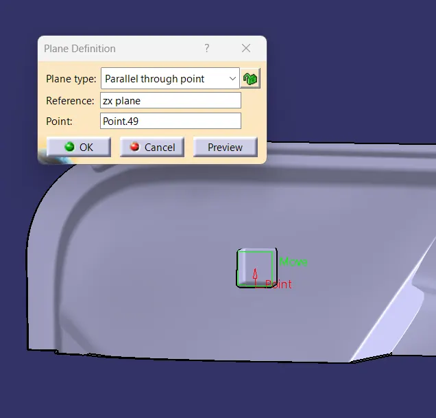
Create the skectch and thicken it.
after create a line and extract and off set y direction close the top wall use the multisection to close back wall
now join all the surfces abd thicknen it .
and create a c section as design standassrdds
and gave draft anlge 1.45 to oter walls and inner walls with 0.5 deg
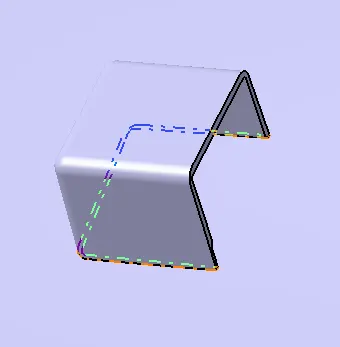
and add to part body
now do draft anaysis
Draft analysis
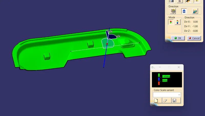
outer walls are clearing with the draft angle of 1.45 deg
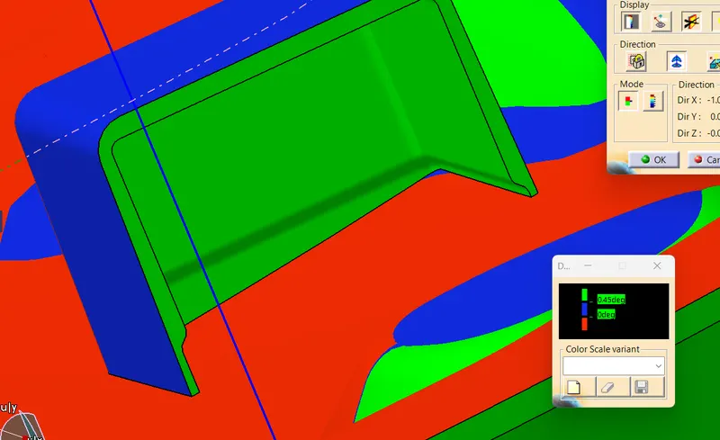
All the inner walls are clearing with 0.45 degg with side core tooilg axis
- Screenshots of the completed design in various orientations (Isometric, Front, Side, and Top View)
Isometric View
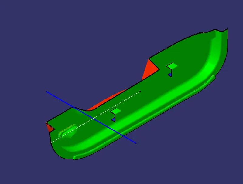
Front View
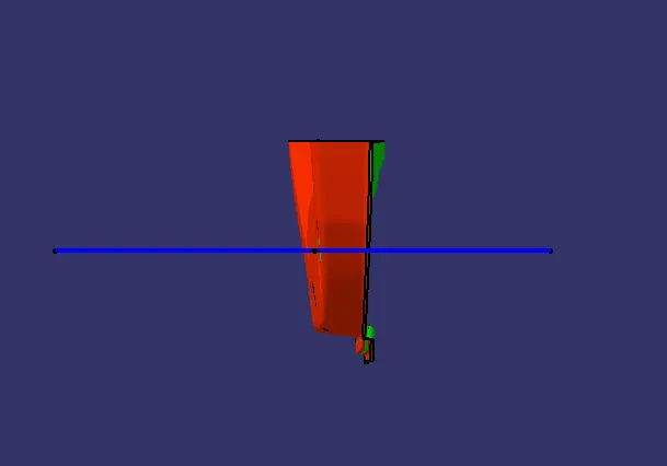
Side View
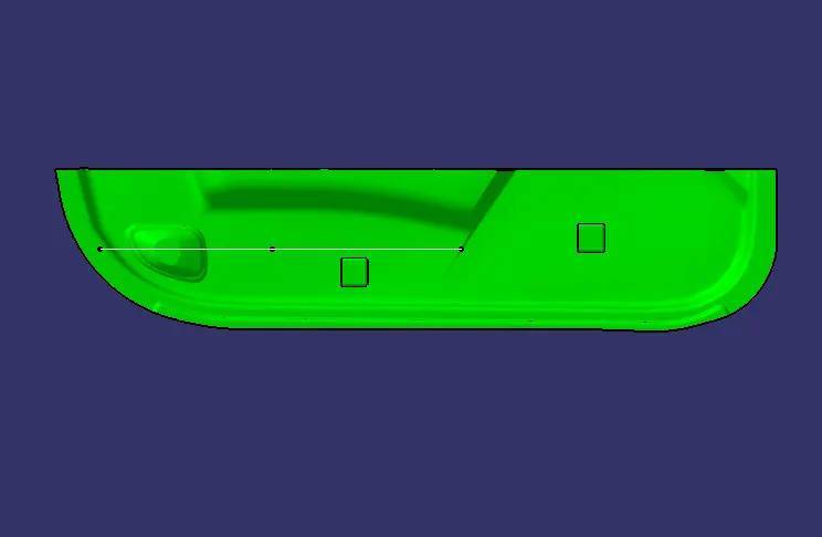
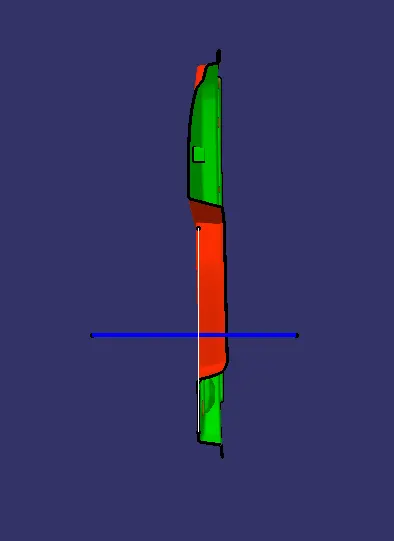
Top View
- Below images/screenshots should be inserted into the challenge box