Project 2 Thermal modeling of battery pack
For a 10 cell series lithium ion battery model, simulate the thermal effects and compare life cycle performance at various temperatures, charge & discharge rates using MATLAB.
Component Requirement:
Battery:
Description
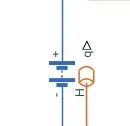
The Battery block represents a simple battery model. The block has four modeling options, accessible by setting the Modeling option parameter to either:
-
Uninstrumented | No thermal port— Basic model that does not output battery charge level or simulate thermal effects. -
Uninstrumented | Show thermal port— Model with exposed thermal port. This model does not measure internal charge level of the battery. -
Instrumented | No thermal port— Model with exposed charge output port. This model does not simulate thermal effects. -
Instrumented | Show thermal port— Model that lets you measure internal charge level of the battery and simulate thermal effects. Both the thermal port and the charge output port are exposed.
Conductive Heat Transfer
Description
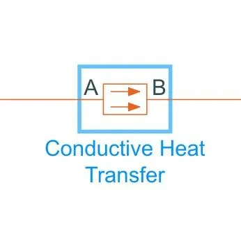
The Conductive Heat Transfer block represents a heat transfer by conduction between two layers of the same material. The transfer is governed by the Fourier law:
Q=k⋅AD(TA−TB),
where:
-
Q is heat flow.
-
k is thermal conductivity of the material.
-
A is area normal to the heat flow direction.
-
D is distance between layers (that is, thickness of material).
-
TA is temperature of layer A.
-
TB is temperature of layer B.
Connections A and B are thermal conserving ports associated with material layers. The block positive direction is from port A to port B. This means that the heat flow is positive if it flows from A to B.
Temperture Source:
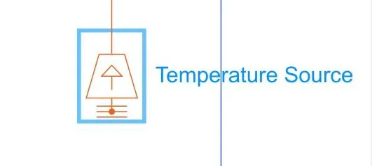
Description
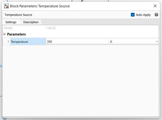
The Temperature Source block represents an ideal source of thermal energy that is powerful enough to maintain specified temperature at its outlet regardless of the heat flow consumed by the system.
The source generates constant absolute temperature, defined by the Temperature parameter value.
Electrical Reference:
Description
The Simulink Editor is a tool for building models. In addition to providing standard methods for working with diagrams in a vector graphics editor, the editor provides shortcuts that help you to add and connect blocks. The Simulink Editor also gives you access to the tools you need for technical operations such as importing data, simulating your model, and analyzing model performance.
Solver Configuration
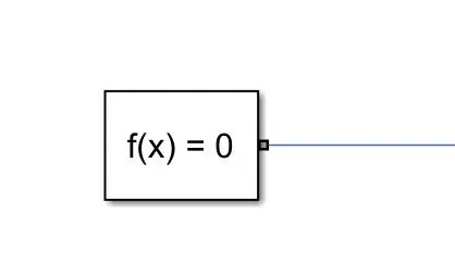
Description
Each physical network represented by a connected Simscape™ block diagram requires solver settings information for simulation. The Solver Configuration block specifies the solver parameters that your model needs before you can begin simulation.
Each topologically distinct Simscape block diagram requires exactly one Solver Configuration block to be connected to it.
Controlled Current Source
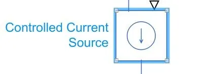
Description
The Controlled Current Source block represents an ideal current source that is powerful enough to maintain the specified current through it regardless of the voltage across the source.
The output current is I = Is, where Is is the numerical value presented at the physical signal port.
The positive direction of the current flow is indicated by the arrow.
Ports
The block has one physical signal input port and two electrical conserving ports associated with its electrical terminals.
PS Constant:
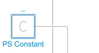
Description
The PS Constant block generates a physical signal of a constant value. You specify the value and unit of the signal as the Constant parameter.
Thermal Refernce:
Description
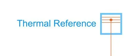
The Thermal Reference block represents a thermal reference point, that is, a point with an absolute zero temperature, with respect to which all the temperatures in the system are determined.
Ports
The block has one thermal conserving port.
Temperture Sensor:
Description
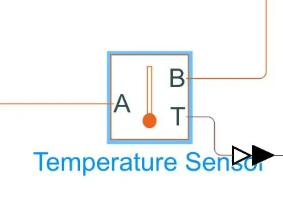
The Temperature Sensor block represents an ideal temperature sensor, that is, a device that determines the temperature differential measured between two points without drawing any heat.
Connections A and B are thermal conserving ports that connect to the two points where temperature is being monitored. Port T is a physical signal port that outputs the temperature differential value.
The block positive direction is from port A to port B. The measured temperature is determined as T = TA – TB.
Ports
The block has the following ports:
A-
Thermal conserving port associated with the sensor positive probe.
B-
Thermal conserving port associated with the sensor negative probe.
T-
Physical signal output port for temperature.
Circuit Model:
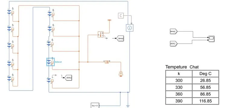
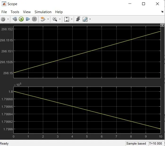
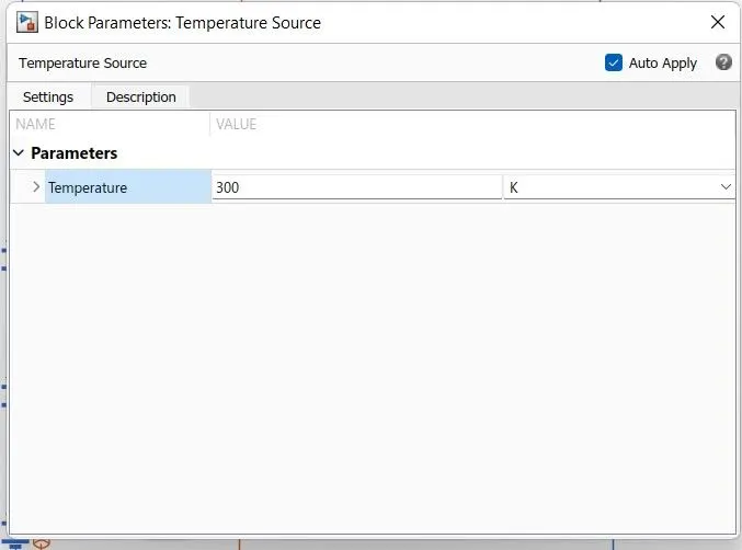
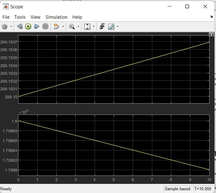
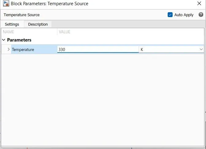
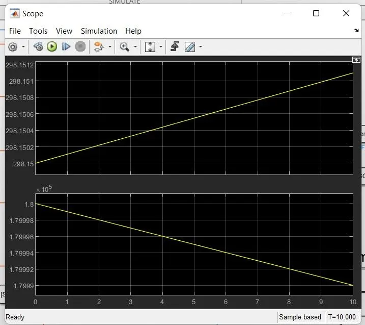
I Tested the series batteries with the constant discharge current on different operating temperatures ranging from 300K to 390K.
Temperature Chart:
Formula: xK − 273.15 = y°C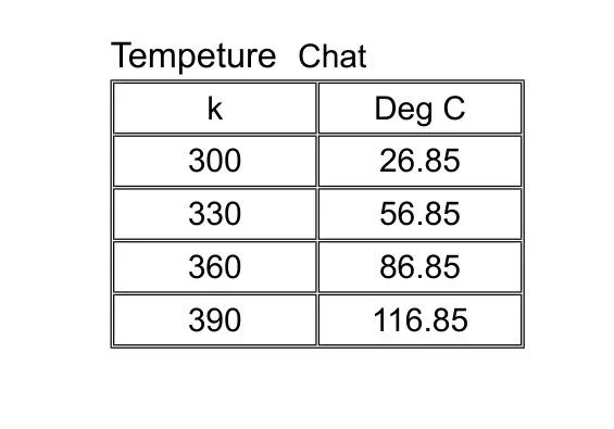
The result on 300K temperature:
The result on 330K temperature:
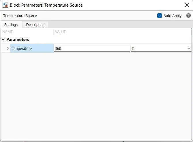
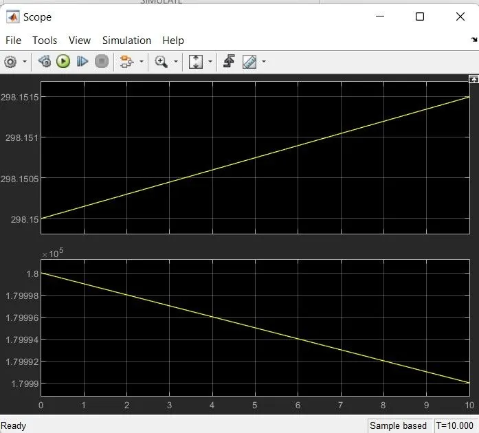
The result on 360K temperature:
The result on 390K temperature: