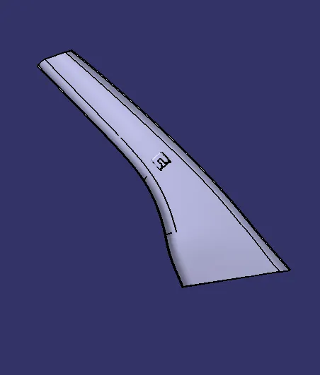
Week 9 - Project - A pillar Design with Master Section
A pillar Design with Master Section
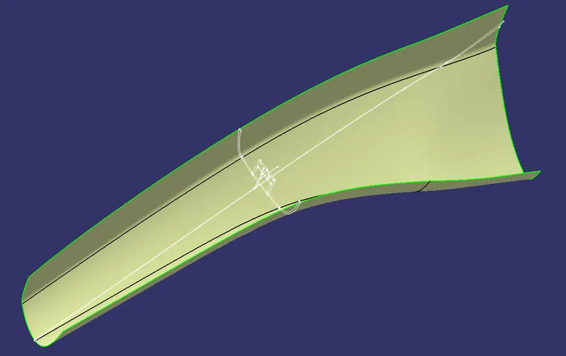
From above A piller master section taken as the input and created the Class A ,Class B and Class C surface and engineering features with indicated in master section.
Now as input of class A surface we have to check condition of class A i.e if there is any patche so firstly we have clear them first and move further
For tha above surface is good no patches are so move further for draft analysis.
To perform the draft analyi firsly create the tooling axiss
Creation of tooling axis
Here the intersection is created by using the master Section.
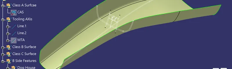
here i draw the two line in y direction with reference of master section
By intersecting the both to line we toling axis.
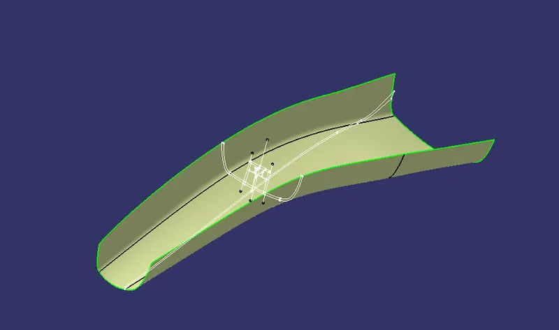
After creating the tooing axis now perform the draft analysis
Draft Analysis on Class A surface
- Go to insert > analysis > feature draft analysis.
- Align the compass with the tooling axis.
- Then, click on the Class-A surface to see if the it is within the permissible limit of the draft values.
- The Class-A surface should turn green and then draft value should be given as 2 degrees.
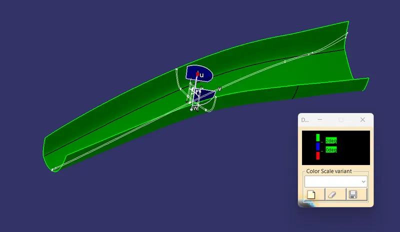
Creating Class B Surface:
Now offsetting the class A surface to 2.5mm. while offsetting some tipicaly geometry has not offsettes so we get patches in the surface.
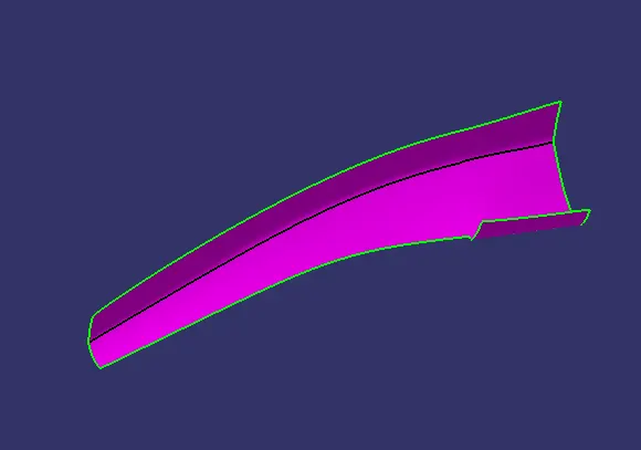
The patch was cleared by using sweep
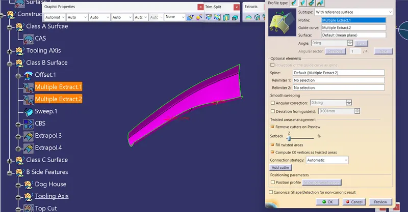
Now i join jion bith surface to make a single surface.
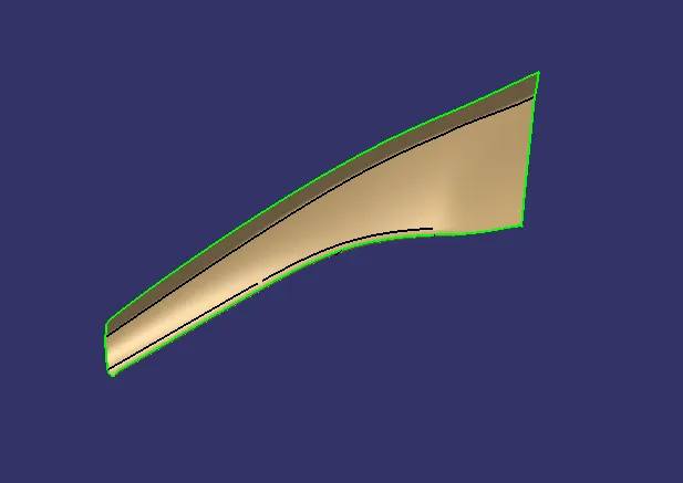
So that my Class B surface is craeted.
Cretaing the C Surface.
To create the class C surface concerning the boundary of the class A surface, I used the sweep command. Initially, I extracted the boundary of the class A surface with tangent continuity, and I sweep the extracted boundary concerning the surface at 93deg (for draft angle) for 5mm to intersect properly with the class B surface. Once we sweep all the surface boundaries of class A, extrapolate the sweeped surfaces until both surfaces got intersected properly, and trim them to remove extended extrapolated surfaces to get a proper sweep boundary throughout the entire surface.
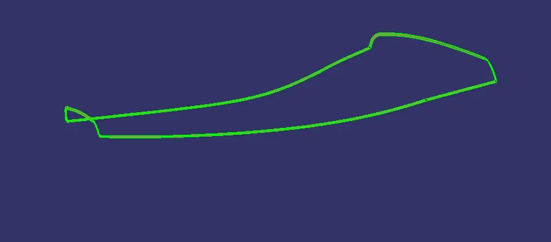
Now joined with Class A surface
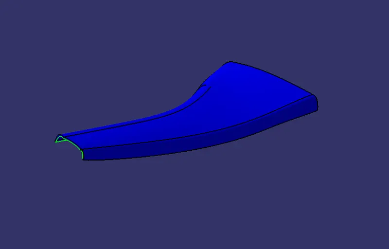
After that trimed with class B surface
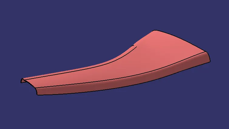
Now we have check that fully closed or not by using boundray command.
So that our Class C surface is crated.
Creating a solid body by using a closed surface :
To create soild body firstly switch to part body work bench and use close surface command to soildify the surface body
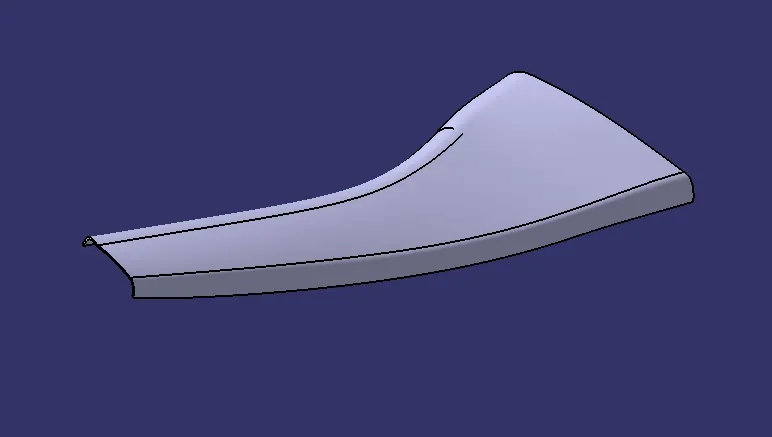
So our part is created no we weill creaet B side feature with the reference of the mastr section.
Dog House Creation
Dog house is an engineering feature used in plastic trim design. Dog houses are used as supporting feature. Sometimes other engineering features like snaps; locators etc. are mounded on them to increase their strength. Dog houses are subjected to draft analysis to prevent breakage of the component during ejection from mould cavity.
Taking reference from the master Section i extract all the required surfaec and trim
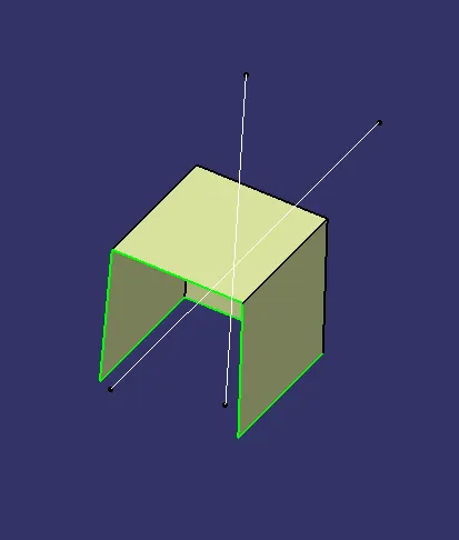
now i thick the surface surface 2 mm
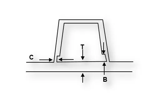
"C" is where the doghouse contacts the backside of the surface
-
Doghouse wall thickness at the intersection of the part wall ( C ) should be 40% or less than the main wall stock ( T ).
-
The height of ( B ) should be between 3.0 – 6.0 mm
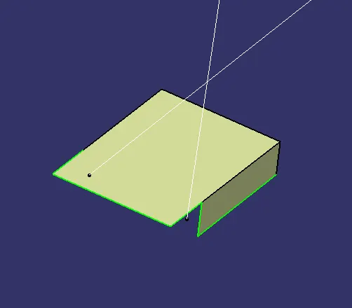
and create C section from the master standards and reference from the master surface
And in the Same way created the rib in the dog hose from the refernce of the master section
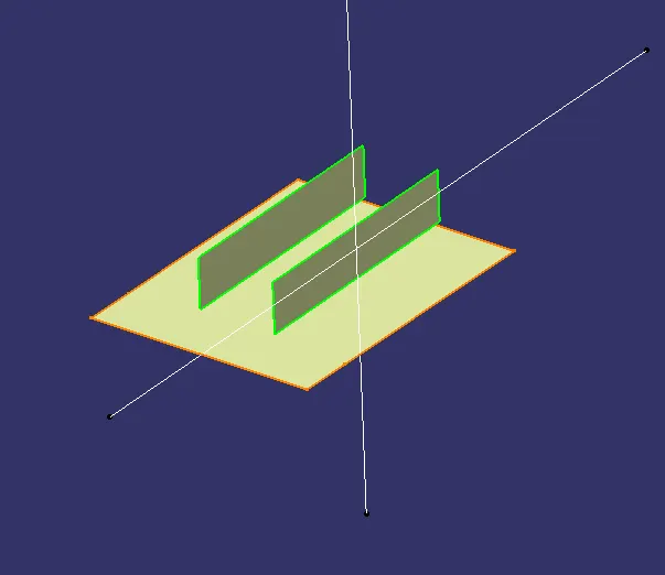
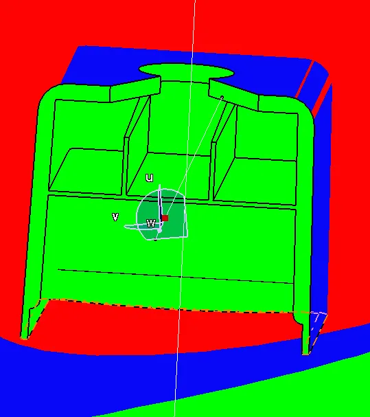
And thicken all the surface to create the dog hose and create the draft a to all the surface outer walls are clearing with the draft angle of 1.45 degAll the inner walls are clearing with 0.45 degg with side core tooilg axis
Draft analysis
outer side of draft angle is cleared with 2.9 deg
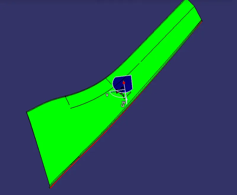
But the below image of class C surface is not cleared with 2.9 deg
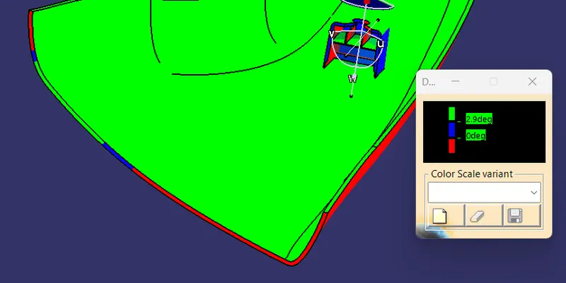
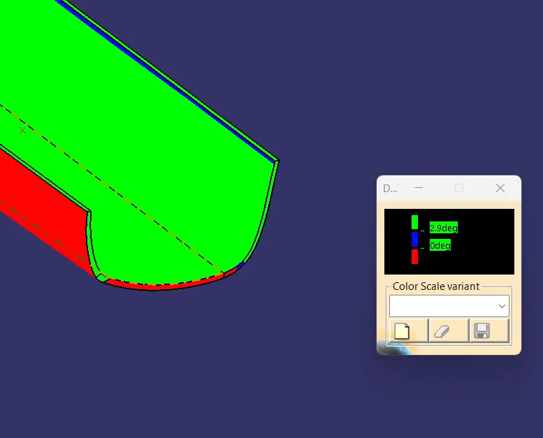
For out side of draft angle of dog house is 1.45 deg
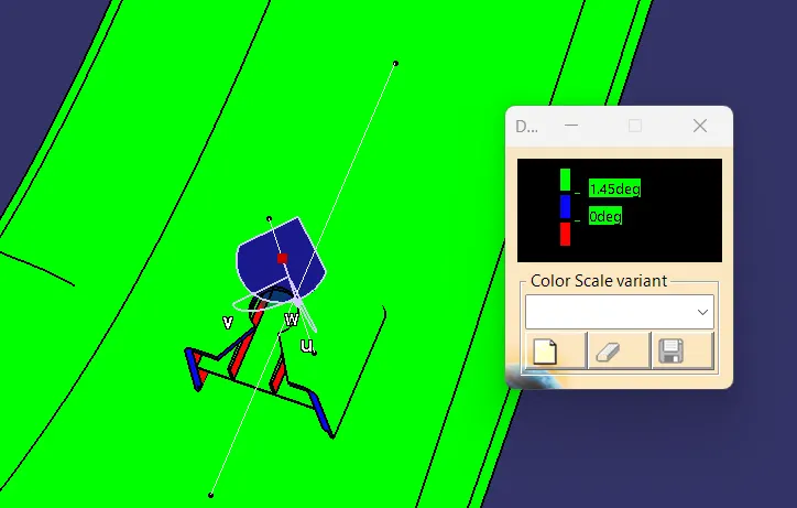
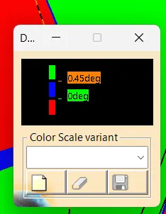
Inner side of draft angle is cleared with 0.45 deg
Isometric View
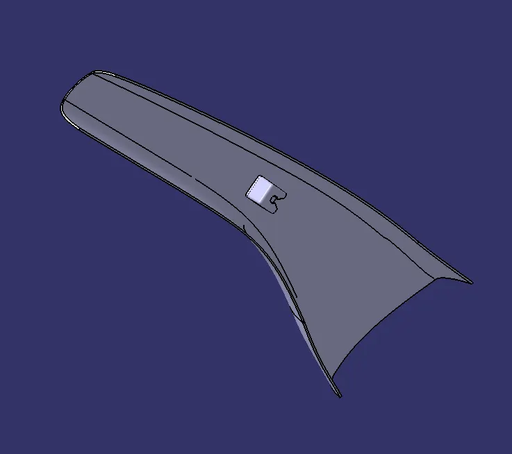
Front View
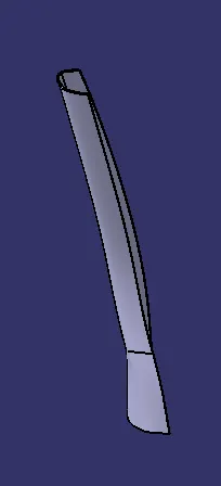
Top View
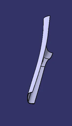
Side View