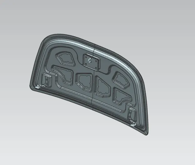
Hood design-Week 2
Aim :
1.Design Hood outer panel, inner panel and the necessary reinforcements by following the Master section mentioned with the design parameter
2.Submit an assembly of Hood inner panel, outer panel, latch, hinge and the reinforcements.
3.A detailed report about the Hood Design which includes a detailed explanation about hood and its components, Latch trajectory, Mastic data, Emboss definitions, manufacturing process like deep drawing and hemming, and all the parameters followed in the design.
4.The report should be well-formatted and should have a good flow of content. Add all the relevant images.
First we will discuss about the use of hood :
The hood (North American English) or bonnet (Commonwealth English) is the hinged cover over the engine of motor vehicles. Hoods can open to allow access to the engine compartment, or trunk (boot in Commonwealth English) on rear-engine and some mid-engine vehicles) for maintenance and repair.
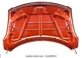
Hood Angle :
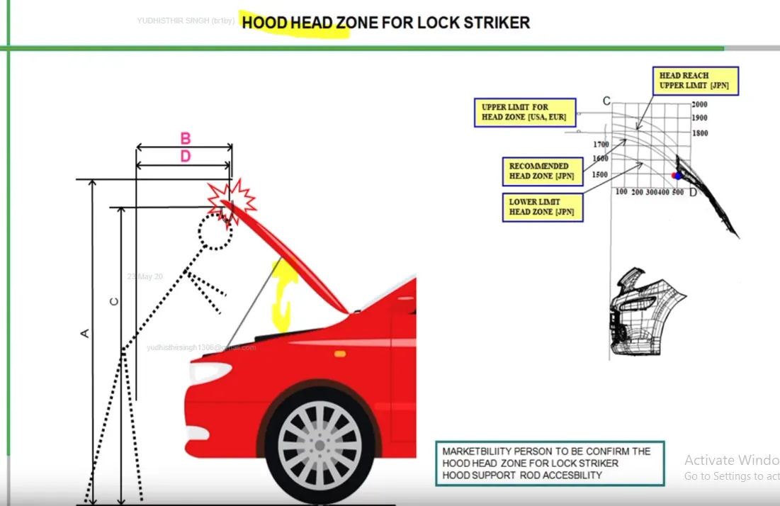
One of design parameter for design of hood is opening angle. This opening angle is being control by supporting rod or gas stay. The length of supporting rod controls the opening angle of hood. Supporting rod is placed on engine and after opening is attached to hood or vice versa.
Parts of a Hood Assembly :
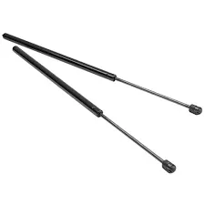
1.Support Rod :
The support rod is used to hold the hood at the hood opening angle and is usually hinged at the engine as shown above.The support rod is usually given a curvature so that it gets strength and the curvature should be less than 35 mm as too much curvature can lead to bending .
2.GAS STAY:
It is also a Hood stay but it is automated or need some slight amount of force then gas itself actuates it and make it work desirably. Advantages: It is automatic in nature
3.Reinforcements
We give reinforcements in the area wherever there is an attachment given such as striker or hinger so that the strength in these areas increase.
4.Wrap Around Distance Concept :
WAD (Wrap-Around Distance) is the geometrically traced distance from the contact point with the Ground Reference Plane, vertically below the front face of the bumper, to any point on the vehicle front structure.
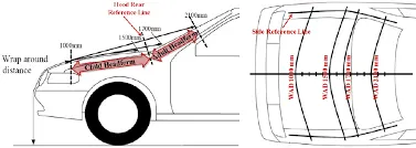
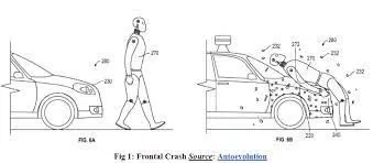
The wrap around distance tells us where exactly the child or adult will end uo colliding on the hood .The distance for child and adult vary according to the euro norms and should be kept in mind while designing the hood .The following pictures gives us a good example :
Now we will talk about hemming process used :
Hemming Process
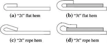
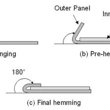
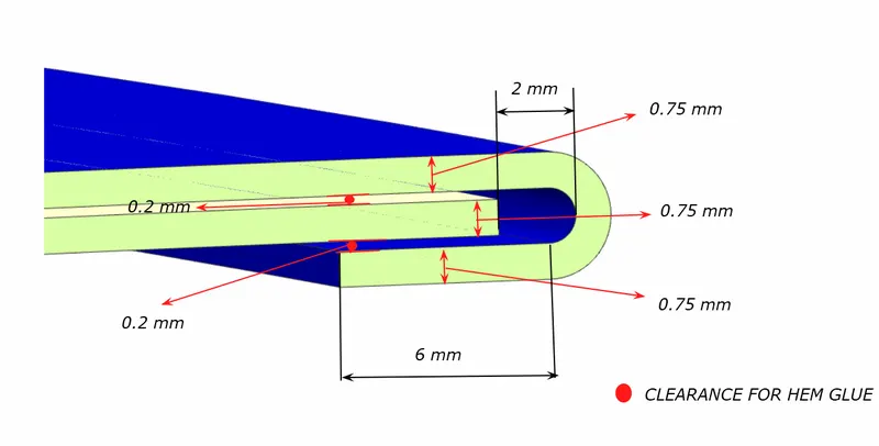
Hemming is a sheet metal forming process in which sheets are joined by bending it usually to 180°. Automotive body panels and automotive parts such as deck-lids, trunk-lids, doors, hoods and tailgates are formed by hemming process.
Hemming is a forming operation in which the edges of the sheet are folded or folded over another part in order to achieve a tight fit. Normally hemming operations are used to connect parts together, to improve the appearance of a part and to reinforce part edges.
Deep Drawing :
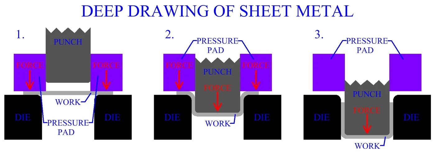
Deep drawing is a process in sheet metal forming by the mechanical action of a punch. A flat sheet metal blank is formed over a single, rigid, shape defning tool half by a flexible rubber diaphragm under uniform hydrostatic pressure.
Here there is few conditions are follow:
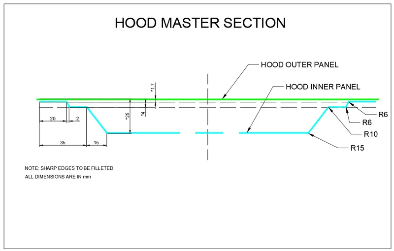
Master Section:
Hemming Data:
Relief rear section:
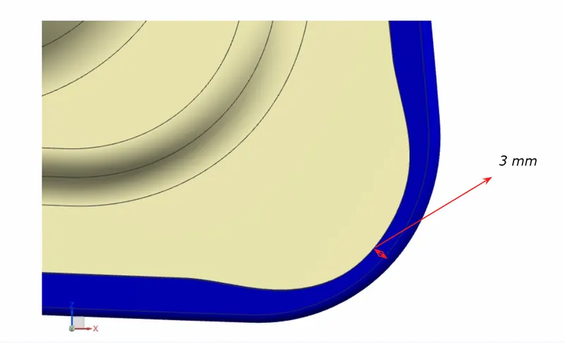
Front relief:
we have dowload all the file shown above the link as input surface's
Now start Assembly modeling in NX by import all the required file into assembly.
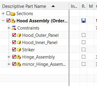
firstly im creating hood inner pannel.
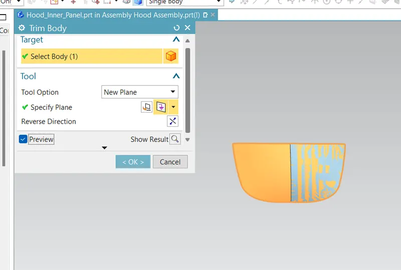
Trim the sheet . we wrok on the half body later mirror to both sides.
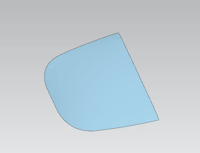
We get the sheet as shown in the below

we will names as parent surface offset to 0 mm and named as working surface and we work on it.
After creating the working surface we offset curve on surface to 20 mm .
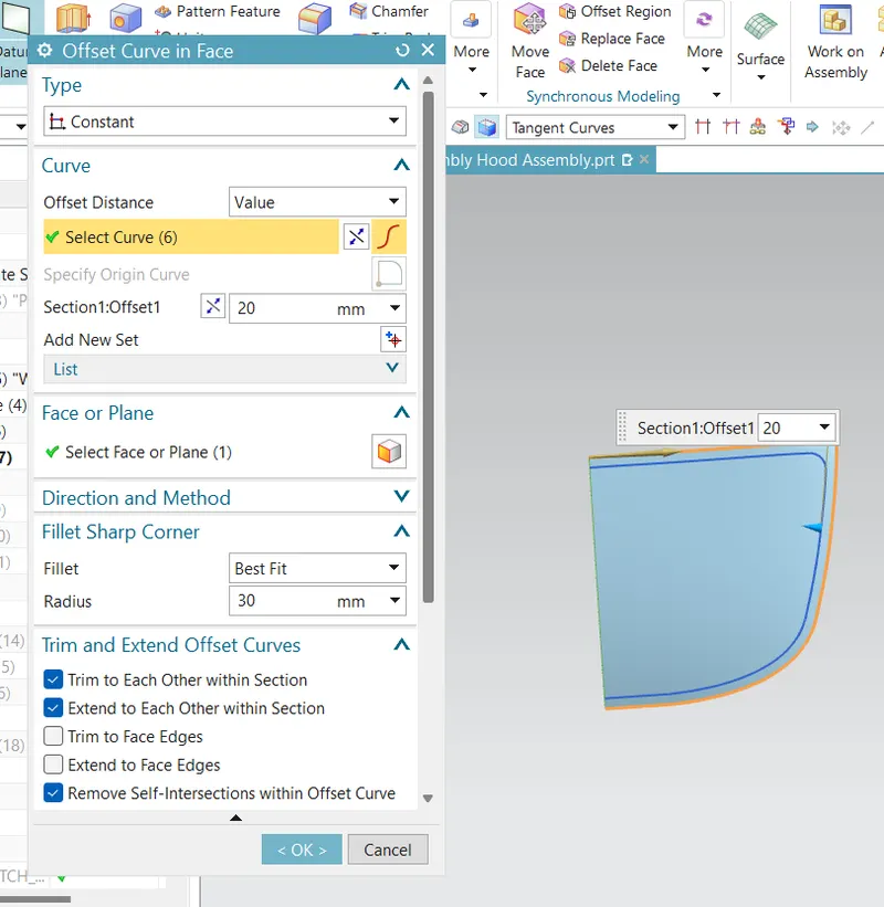
And trim the sheet.
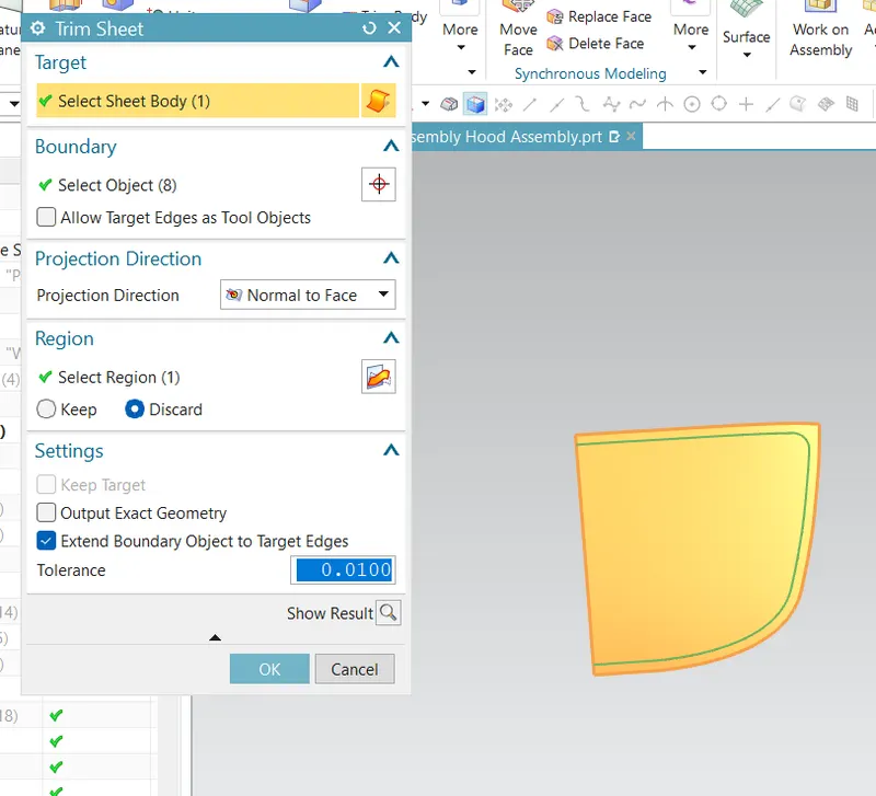
We get shhet as shown in below
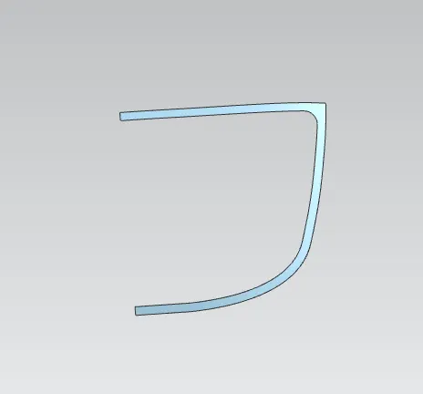
Now we will create the second flange by offsetting the working surface by 4 mm

Now we will create the second flange by offsetting the working surface by 25mm
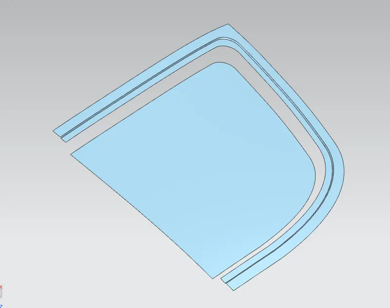
Using through curves we will connect these three surfaces
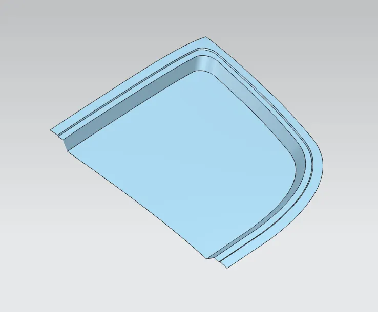
After gettinh the three surface use face blend to avoidthe sharp corners and bend as per the master section.
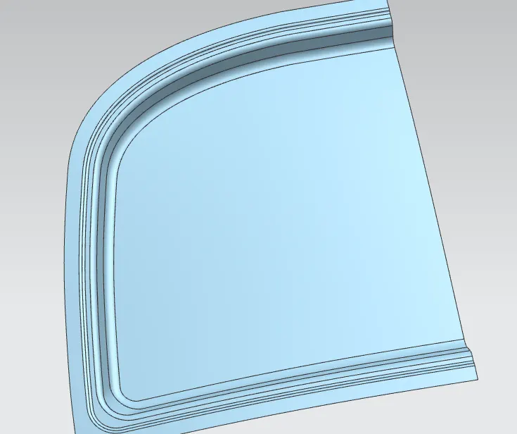
Now we will work on the embosses for the inner region for that i draw a sketch.
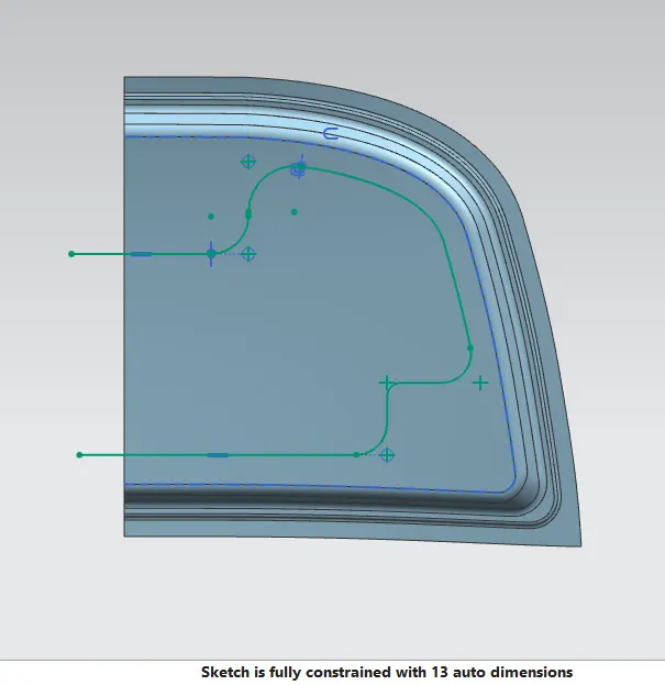
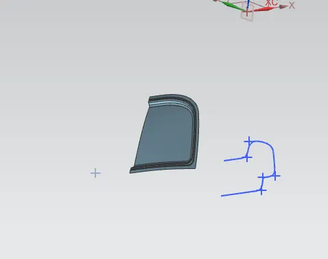
Next i will project curve on the surface by using project curve.
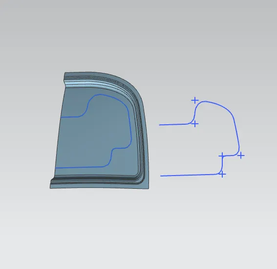
by using emboss command make the first emboss.
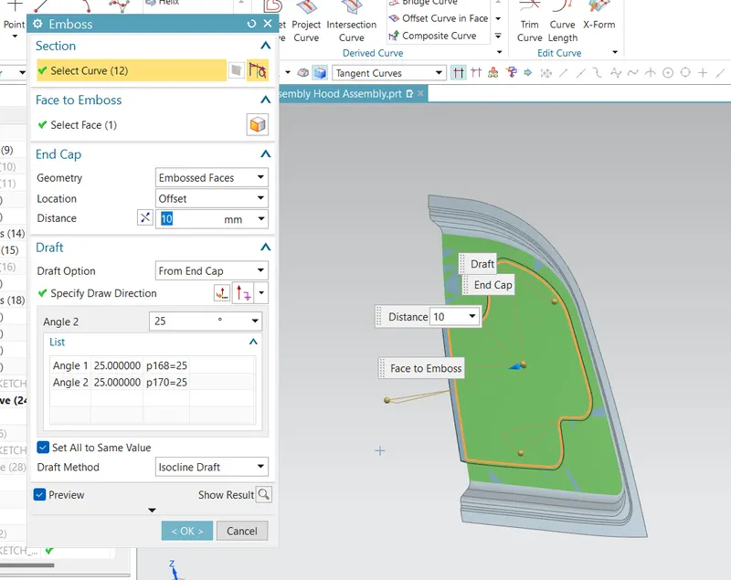
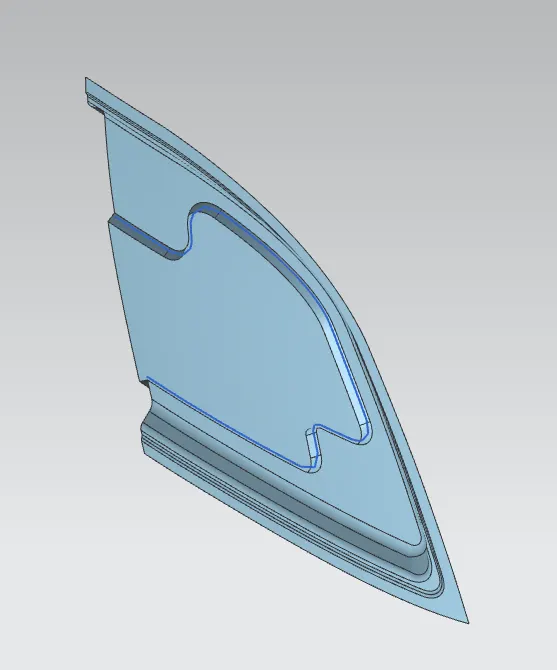
so that first emboss is created and now i use edge blend to avoid sharp corners.
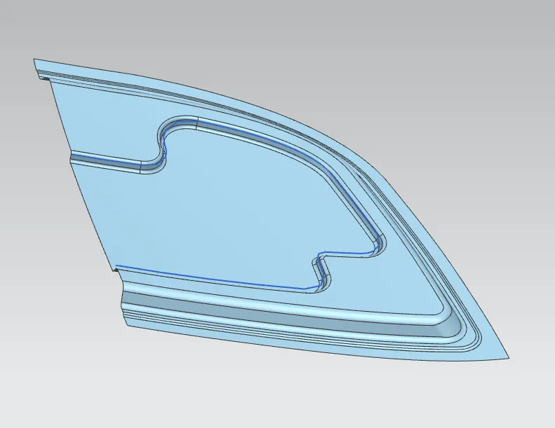
So that first emboss is created now we will work on second emboss for that i create a another sketch.
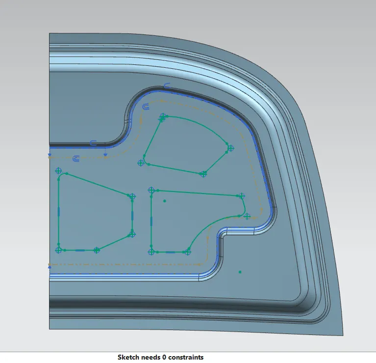
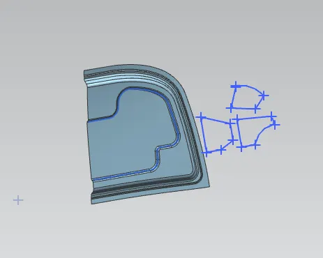
project the skecth on the surface for the second emboss.
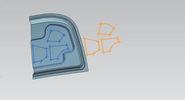
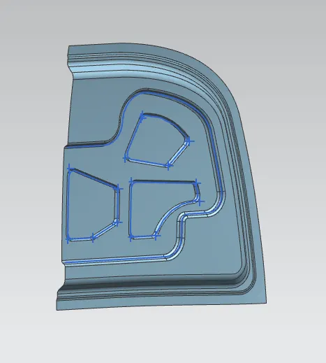
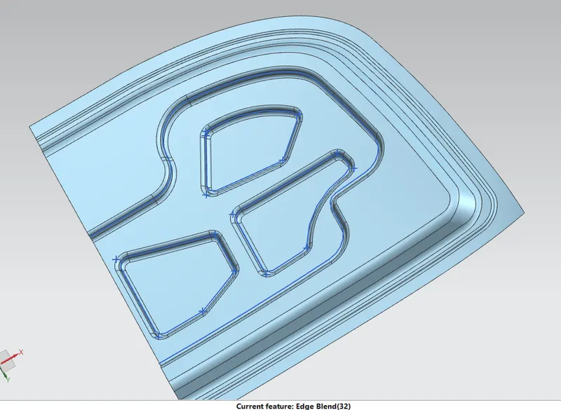
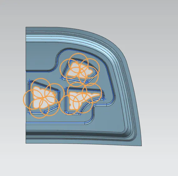
create a another sketch to remove material and majestic clearance and projected on the surface.

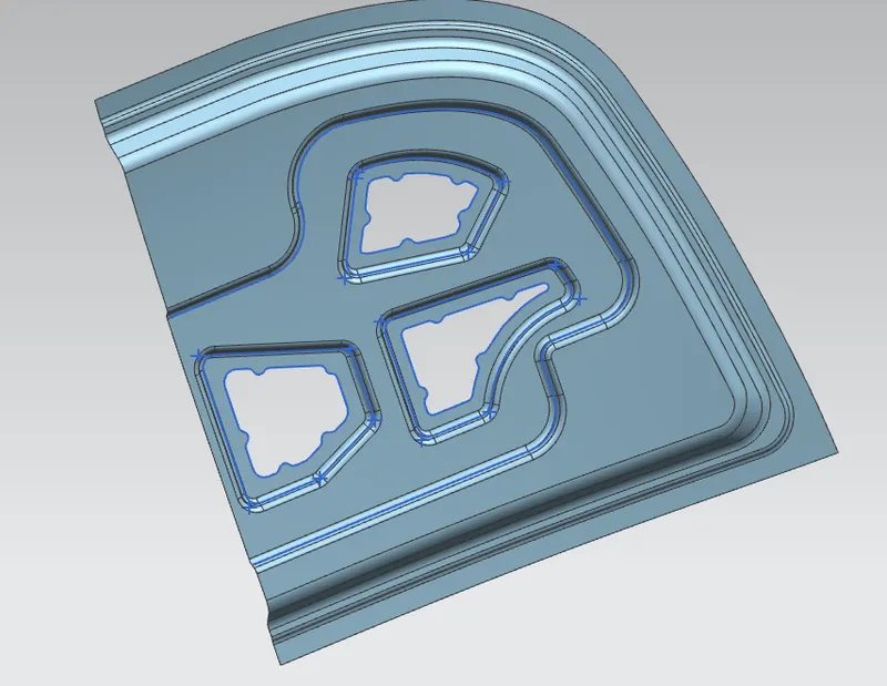
Trim the Sheet.
Now i will create the hing assembly emboss.For that create a datum to create falte emboss.
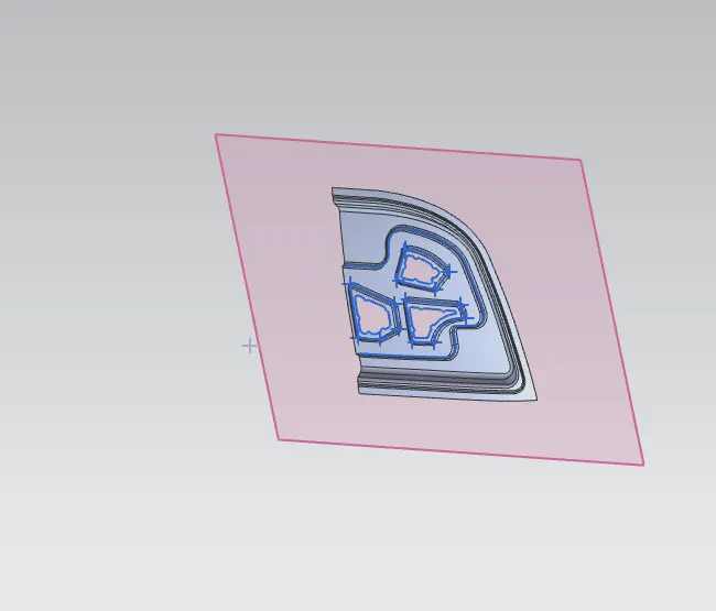
Next i created Sketch and project in the surface.
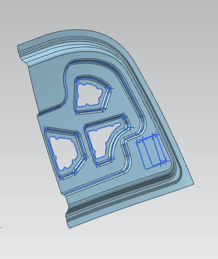
After that i will create the emboss for the hing assembly.
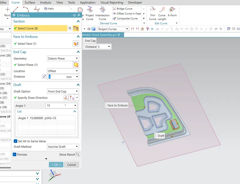
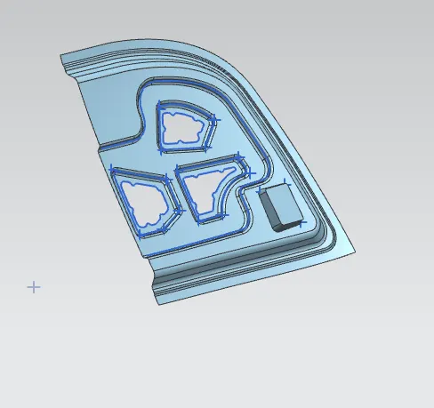
use edge belnd to avoid the sharp corners on the hinge assembly.
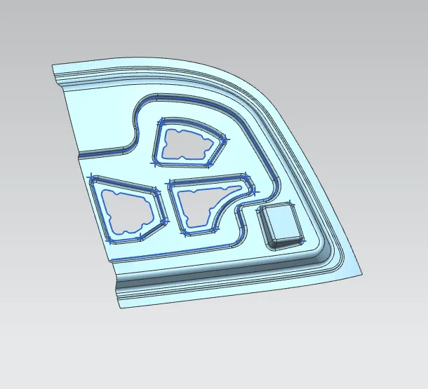
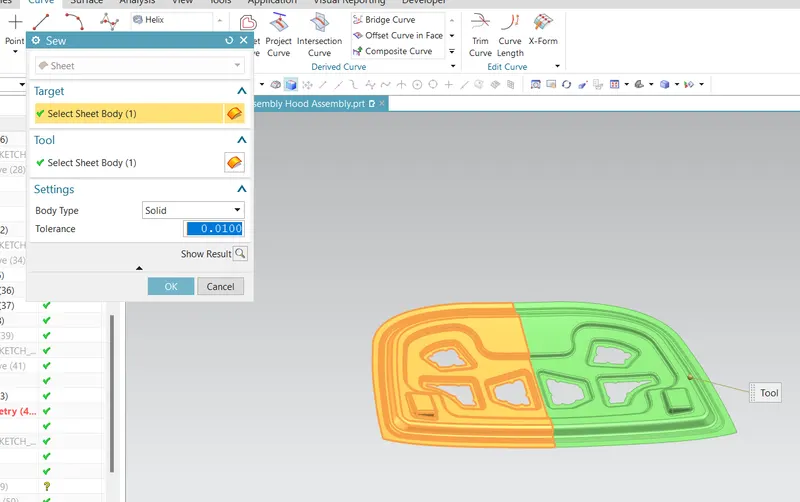
mirror the surface by using mirror geometry and combine the both the surface by using the srew command.
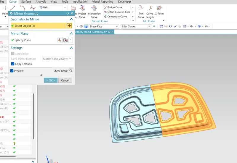 .
.
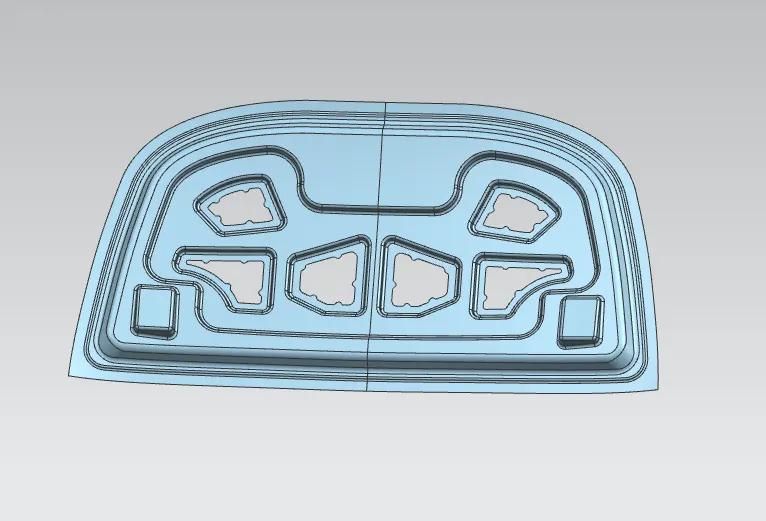
So that my hing emboss is created.
POSITION OF STRIKER AND HINGE
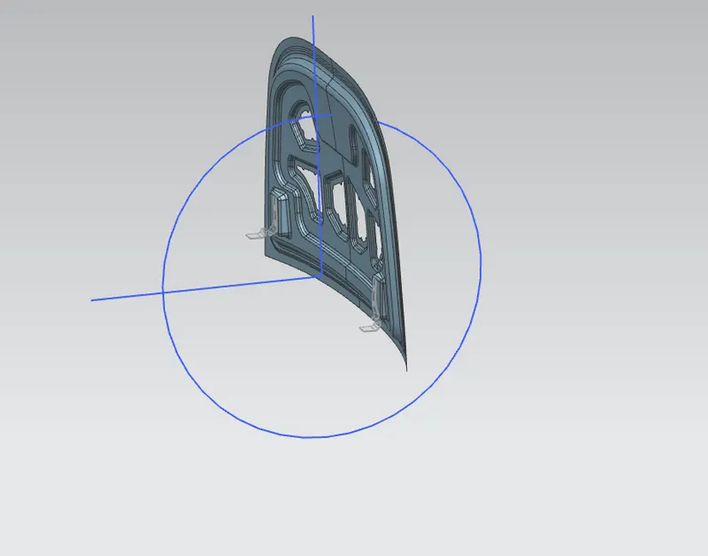
For the proper opening and closing of the hood, the striker should be perpendicular to the trajectory of the hood. For this, hinge is assembled at its position. Once it is placed, hinge axis is drawn.
- To check the hinge axis as the center we draw a big circle to the position the latch in such a way that it is perpendicular to the hood trajectory.
- In between the two hinges, the striker is perpendicular to the midpoint of two hinges, because while closing and opening of latch and striker the opening position be similar actions.
Assembly of Hings:
Hinges is the assembly of components connected to the door and body of the vehicle, linked to each other and capable of rotating around the same axis. Conventional system consists of two hinges for each door, an upper hinge and a lower hinge.
Assembly the hings by using the constrains.
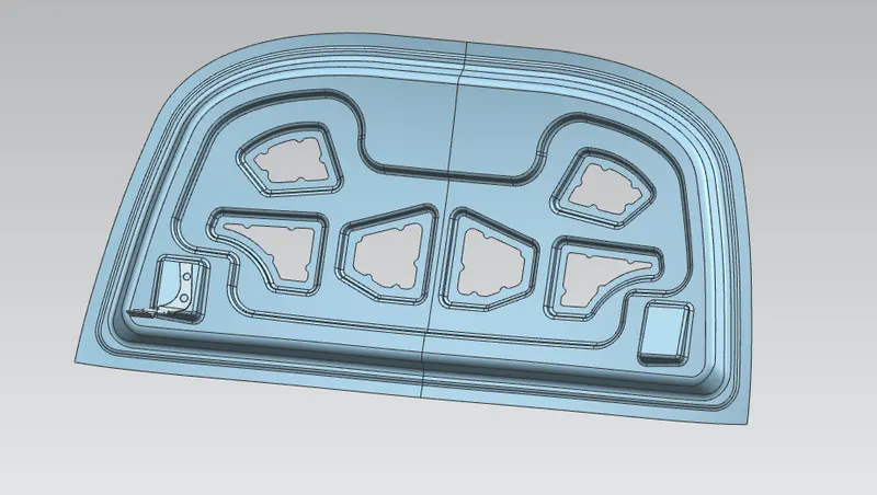
Mirror it by using the mirror geometry.
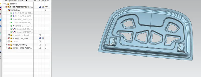
Now i have crete a striker emboss and assembly
STRIKER ASSEMBLY
The door striker plates are installed in the door jambs, and precisely aligned with the door latches so that the latches catch onto the striker plate when the doors are closed. The door striker plate is made of hardened steel to resist wear as it is subjected to constant contact with the door latch.
The hood latch system begins inside the compartment of the car, hood release handle located onthe driver's side. The hood release handle attaches to a cable which then routes through the dashboard towards the front of the vehicle.
- Firstly create a point on both hings and create aline by joining the botn the points
- crete a circle that pass the striker to latch geomery.
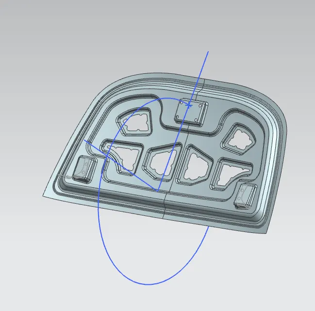
And thicken the Surface.
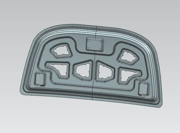
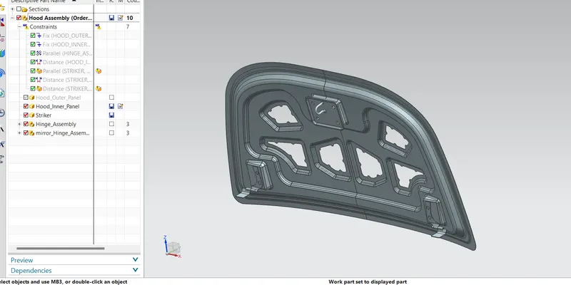
so that my inner pannel is prepared now a give constrains to assemblt stiker ti inner panel
.
next we have work on outer panel
CORNER RELIEF
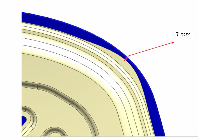
- Relief is provided onto the part or component in order to remove any stresses developed in a particular area i.e sharp corners that takes place during the hemming process is carried out. Thus corners are rounded or chamfered.
- Relief of 3 mm from sheet metal for Roll hemming process.
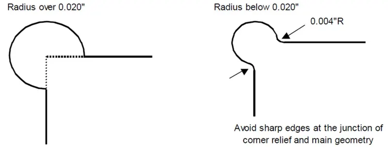
Make Outer pannel current work part.
- Trim the surface
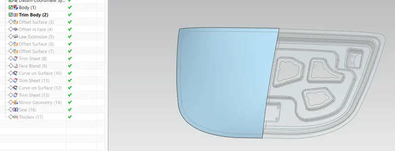
offset the surface
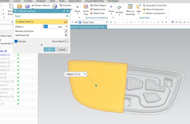
Offset curve on surface
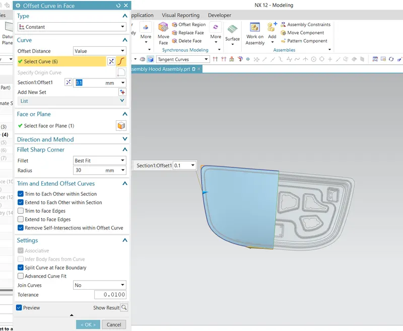
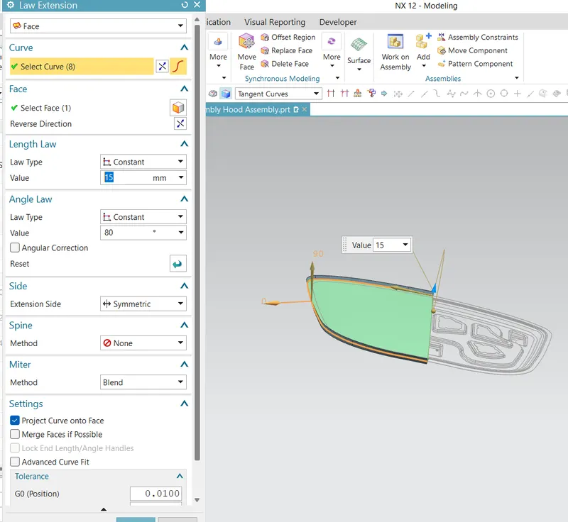
use law of extension for the offset curve to crate the hemming flange and off set 15 mm.
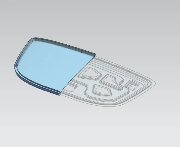
by useing three face blend we create the heamming flange.
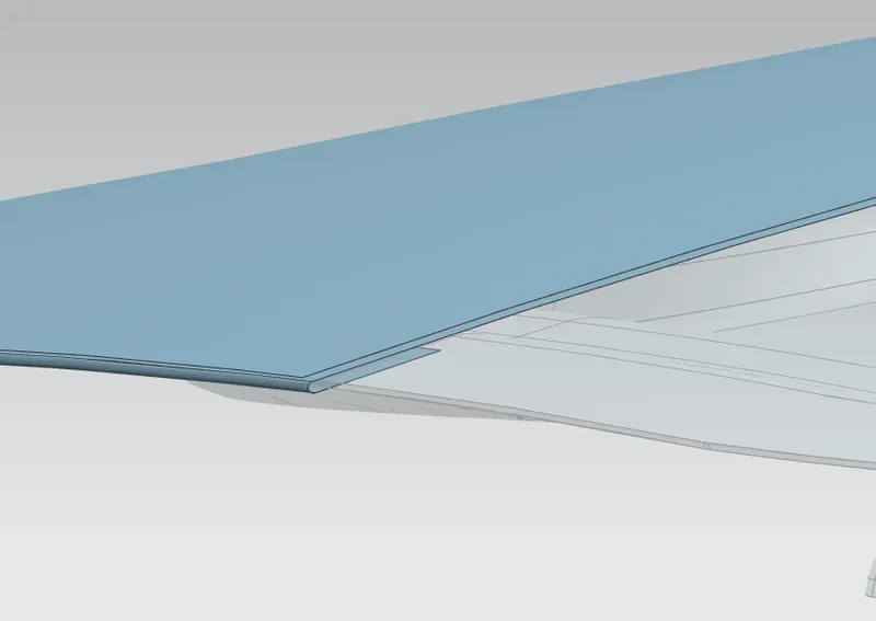
After give the corner relifs by using curve on surface and trin the sheet.
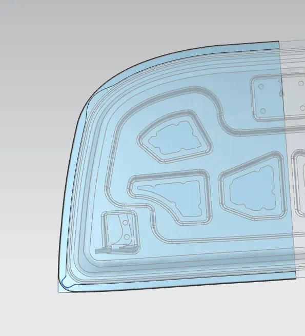
mirror the gemoetry and scre and the thicken the surface.
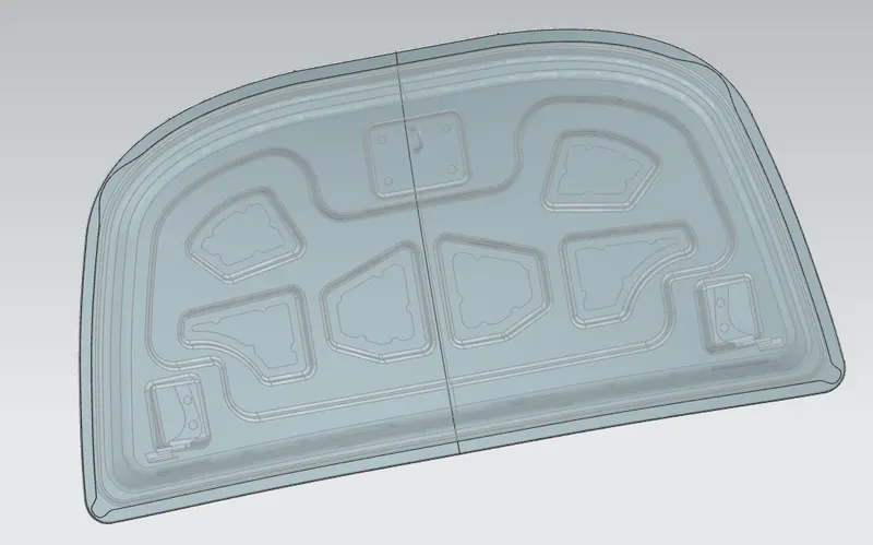
so hood design is completed