Week 11 - Final project
AIM
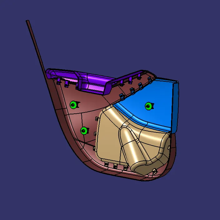
To create a door interior part from the inputs of class A surface along with master section by following the design rules followed in tier 1 and OEM industries in catia v5
INPUT OF CLASS A SURFACE
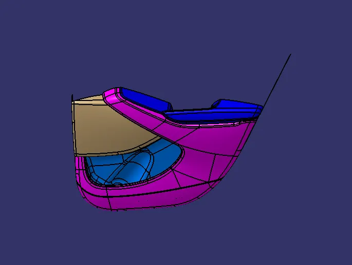
Since the input class A surface is containing four different parts(class A). So class B and C for all the surface has been created in separate catpart. Also performing draft analysis and tooling axis separately. finally all the surface have assembled together in one catproduct.
LOWER SUBSTRATE:
Class A Surface
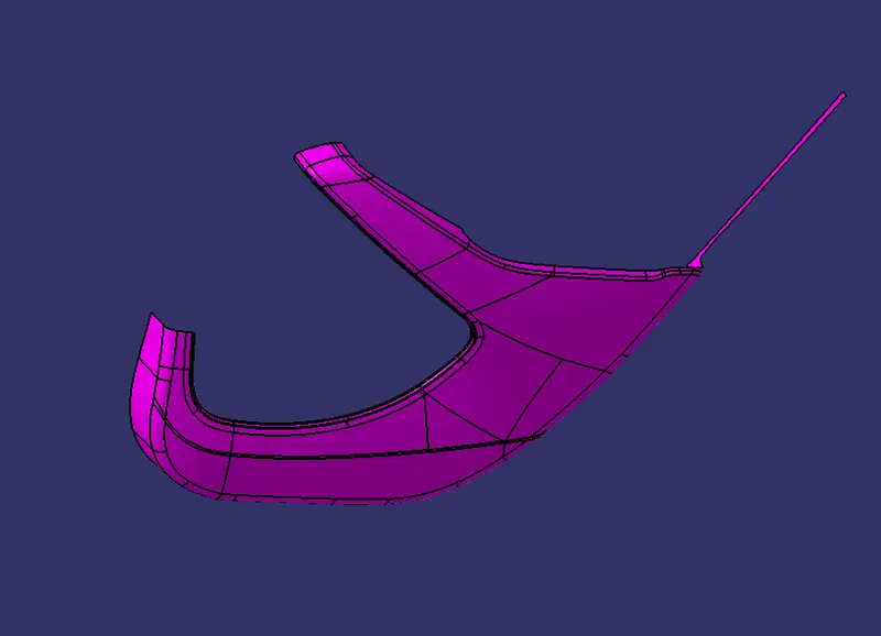
So that firstly we have to Class A surface as taking as input.
Class A surfcae is good there is no patches so we will move further
Next step is Draft Analysis on Class A surface to perform draft analysis on class we have create the tooling axis
1.Creating tool axis .
- To create the tooling axis, we need the proper orientation or view that gives the correct features and draft available in the component.
- So here the component view from the Y direction gives the proper view for the tool to see the features present in the geometry.
- Now i Extracted the base surface.
- Center point is created by using the on surface at zero.
- One that point create a line.
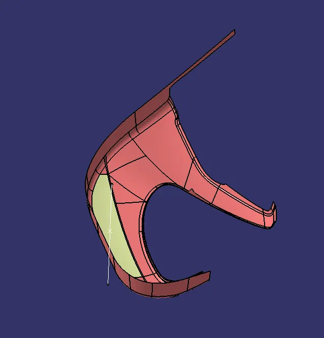
Drafting Class A Surface:
- Go to insert > analysis > feature draft analysis.
- Align the compass with the tooling axis.
- Then, click on the Class-A surface to see if the it is within the permissible limit of the draft values.
- The Class-A surface should turn green and then draft value should be given as 3 degrees.
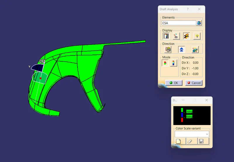
Draft Analysis is completed.
So now we have to create Class B Surface
Cretaing the B Surface.
Now offsetting the class A surface to 2.5mm. while offsetting some tipicaly geometry has not offsettes so we get patches in the surface.
we have clear all the patch by extractig method
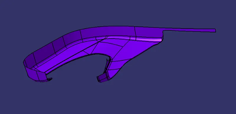
Here we dont have ant patches.
So that i have created the Class B surface.
Cretaing the C Surface.
To create the class C surface concerning the boundary of the class A surface, I used the sweep command. Initially, I extracted the boundary of the class A surface with tangent continuity, and I sweep the extracted boundary concerning the surface at 93deg (for draft angle) for 5mm to intersect properly with the class B surface. Once we sweep all the surface boundaries of class A, extrapolate the sweeped surfaces until both surfaces got intersected properly, and trim them to remove extended extrapolated surfaces to get a proper sweep boundary throughout the entire surface.
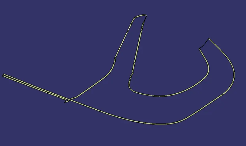
Now, join both class A and sweep boundary to get the complete class C surface.
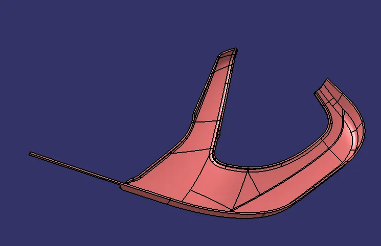
Now, unhide the class B and class C surfaces. Check whether all the sides of class B and Class C surfaces are intersecting properly with each other, to get a closed surface by trimming class B and class C surfaces. If the class B and class C sides are not intersected properly, we need to extrapolate the sides of the class B surface which are not intersecting with the class C surface. Now, check class B and class C surface By interseting tool whether all the sides are intersecting or not with each other. Once the surfaces are intersecting properly trim them together to get a closed surface.
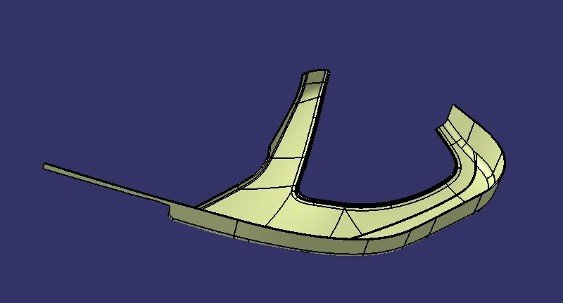
Now we have check that fully closed or not by using boundray command.
So that our Class C surface is crated.
Creating a solid body by using a closed surface :
To create soild body firstly switch to part body work bench and use close surface command to soildify the surface body
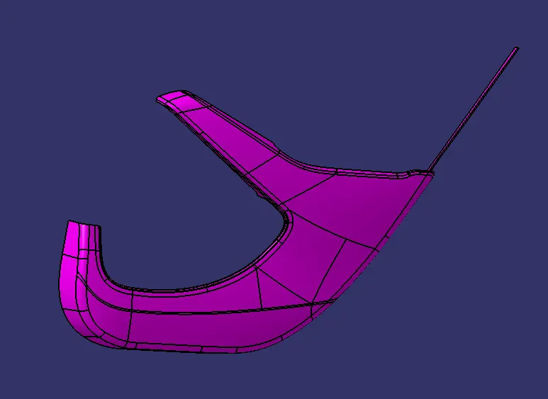
Door Arm Rest:
Class A Surface
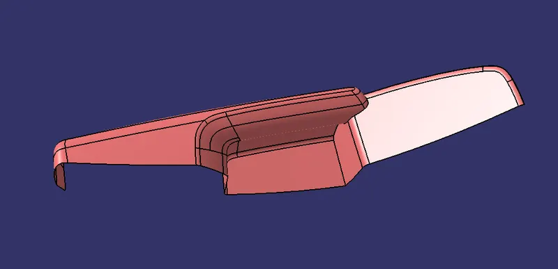
So that firstly we have to Class A surface as taking as input.
we found the some patch is available on the surface. so that i need to develop the Class A surface by acceptancesof the class A team.
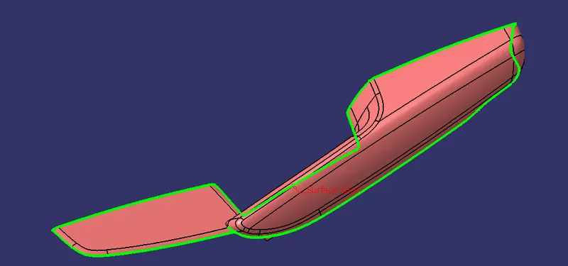
Developed Class A surface.
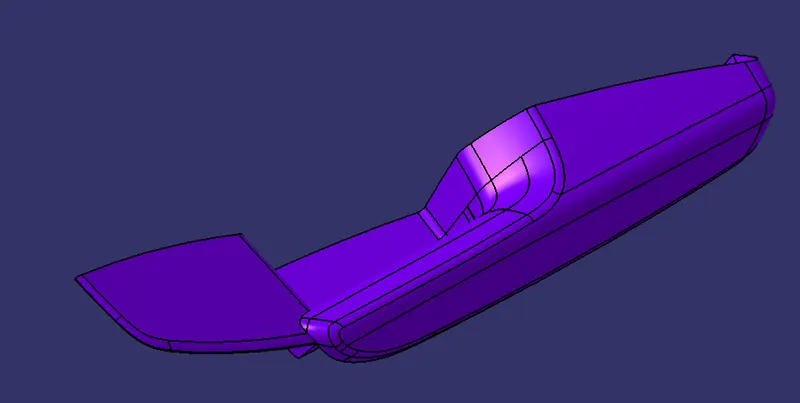
Now, class A surfcae is good there is no patches so we will move further
Next step is Draft Analysis on Class A surface to perform draft analysis on class we have create the tooling axis.
1.Creating tool axis:
- Now i Extracted the base surface.
- create point with 0 axis.
- create a dummy axis.
- by interseting of dummy tooling axis with XZ axis
- By bisecting method crate a tooling axis.
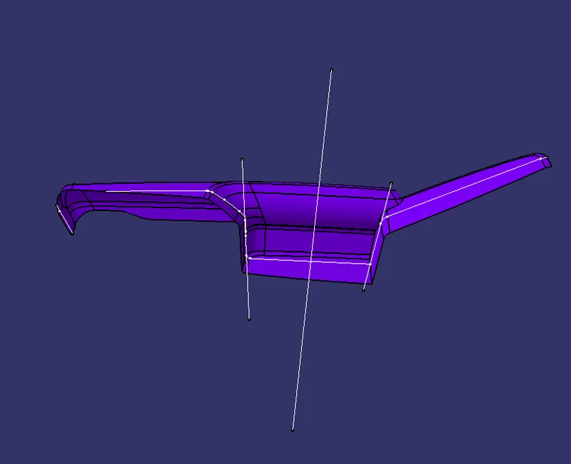
Draft analysis on Class A Surface .
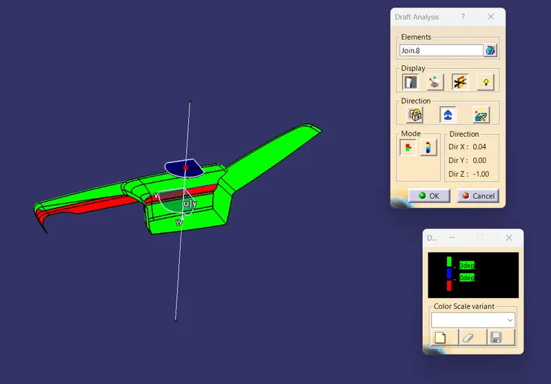
Here some area is not clear in draft analysis because door arm rest is not single surface it is two surface to clear draft analysis we have to nees side core axis.
creating B surfaces :
Now offsetting the class A surface to 2.5mm. while offsetting some tipicaly geometry has not offsettes so we get patches in the surface.
we have clear all the patch by extractig method.
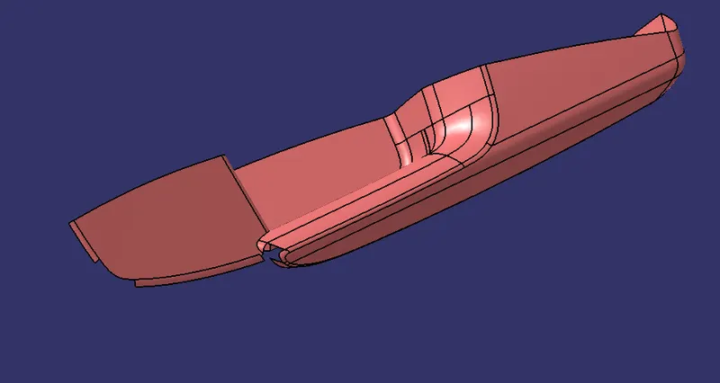
By using the join command some surface are removedto clear the patch.
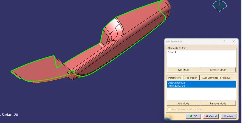
Draw the splineand use to multi section to clear the patch.
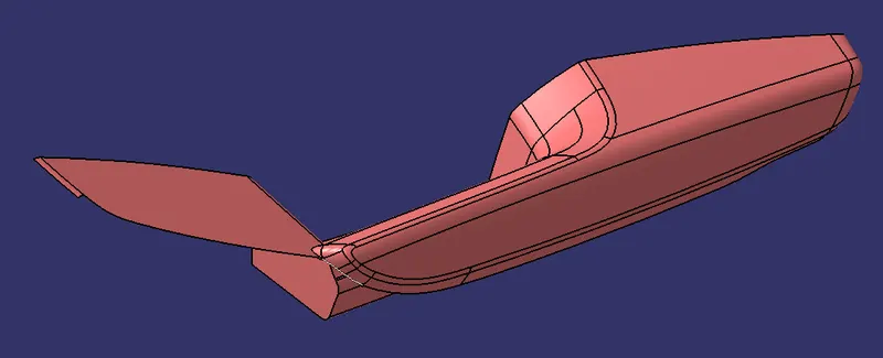
After that i used the sweep command and some explotion are made to clean the pacth and by join command i joined the surface.
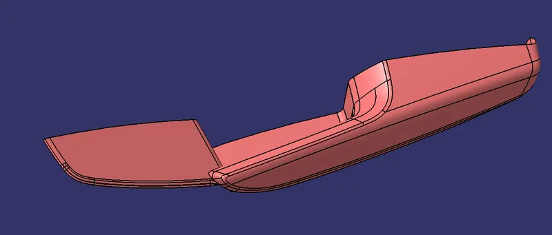
So that Class B surface is created.
Cretaing the C Surface.
To create the class C surface concerning the boundary of the class A surface, I used the sweep command. Initially, I extracted the boundary of the class A surface with tangent continuity, and I sweep the extracted boundary concerning the surface at 93deg (for draft angle) for 5mm to intersect properly with the class B surface. Once we sweep all the surface boundaries of class A, extrapolate the sweeped surfaces until both surfaces got intersected properly, and trim them to remove extended extrapolated surfaces to get a proper sweep boundary throughout the entire surface.
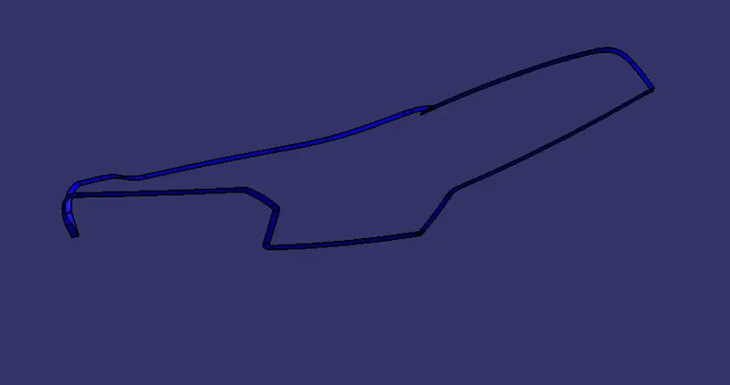
Now, join both class A and sweep boundary to get the complete class C surface
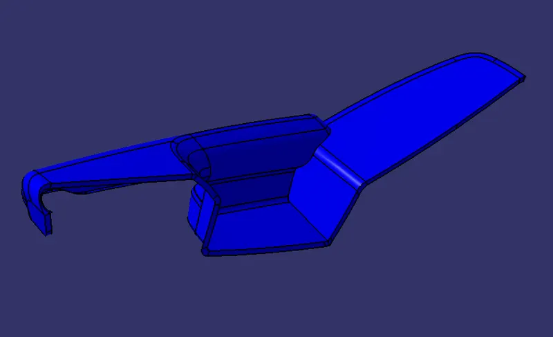
Now, unhide the class B and class C surfaces. Check whether all the sides of class B and Class C surfaces are intersecting properly with each other, to get a closed surface by trimming class B and class C surfaces. If the class B and class C sides are not intersected properly, we need to extrapolate the sides of the class B surface which are not intersecting with the class C surface. Now, check class B and class C surface By interseting tool whether all the sides are intersecting or not with each other. Once the surfaces are intersecting properly trim them together to get a closed surface.
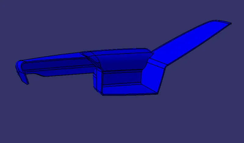
Now we have check the our Bumper fully closed or not by using boundray command.
finally our Door Arm Rest is obatained.
Creating a solid body by using a closed surface :
To create soild body firstly switch to part body work bench and use close surface command to soildify the surface body.
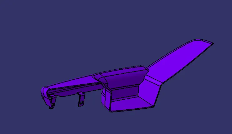
Bottle Holder:
Class A Surface
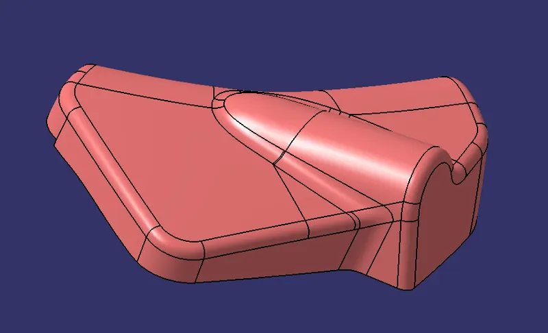
So that firstly we have to Class A surface as taking as input.
Class A surfcae is good there is no patches so we will move further
Next step is Draft Analysis on Class A surface to perform draft analysis on class we have create the tooling axis
1.Creating tool axis :
- Create a point in the centre of the component.
- By using the intersecting method create a tooling axis.
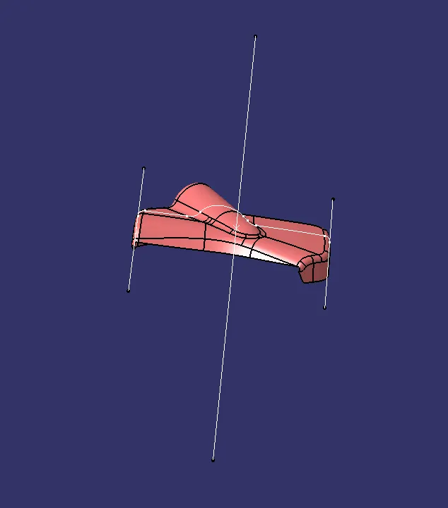
Draft analysis on clsaa A surface:
After creating the Tooling axis we have to perform the draft analysis on the class A surface.
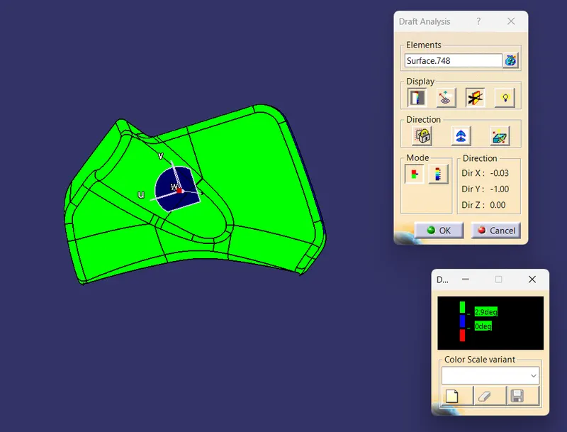
Class B Surface Creation:
By offseting of 2.5 mm we create a class b surface here we dont have any patches so our B surface is ceated.
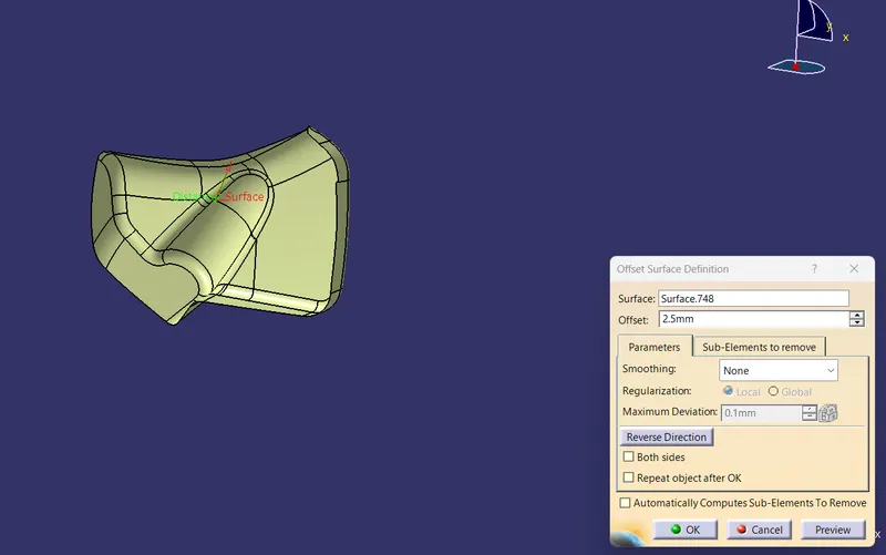
Class C Creation:
To create the class C surface concerning the boundary of the class A surface, I used the sweep command. Initially, I extracted the boundary of the class A surface with tangent continuity, and I sweep the extracted boundary concerning the surface at 93deg (for draft angle) for 5mm to intersect properly with the class B surface. Once we sweep all the surface boundaries of class A, extrapolate the sweeped surfaces until both surfaces got intersected properly, and trim them to remove extended extrapolated surfaces to get a proper sweep boundary throughout the entire surface.
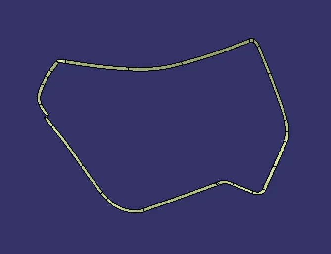
Now, join both class A and sweep boundary to get the complete class C surface
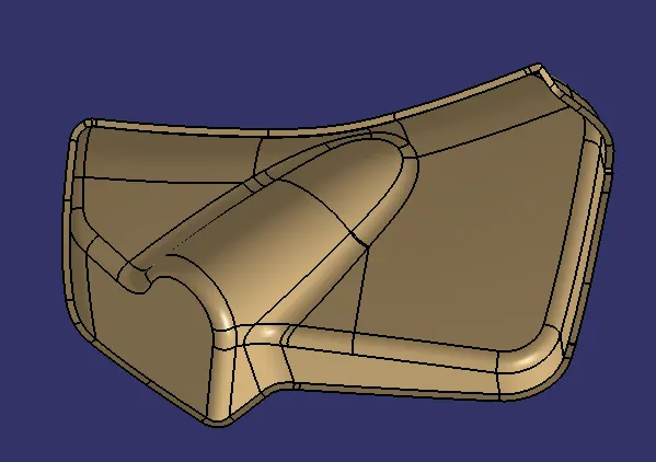
Now, unhide the class B and class C surfaces. Check whether all the sides of class B and Class C surfaces are intersecting properly with each other, to get a closed surface by trimming class B and class C surfaces. If the class B and class C sides are not intersected properly, we need to extrapolate the sides of the class B surface which are not intersecting with the class C surface. Now, check class B and class C surface By interseting tool whether all the sides are intersecting or not with each other. Once the surfaces are intersecting properly trim them together to get a closed surface.
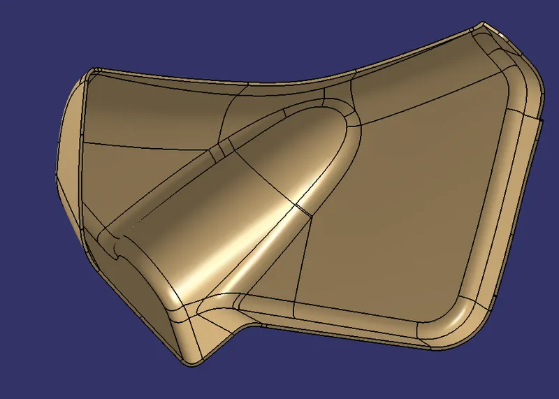
Now we have check the our bottle holder fully closed or not by using boundray command.
finally ourBottle holder is obatained.
Creating a solid body by using a closed surface :
To create soild body firstly switch to part body work bench and use close surface command to soildify the surface body.
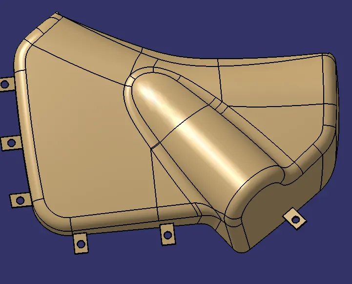
Map Pocket:
Class A Surface
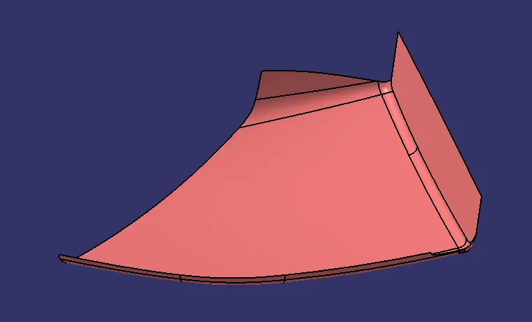
So that firstly we have to Class A surface as taking as input.
Class A surfcae is good there is no patches so we will move further
Next step is Draft Analysis on Class A surface to perform draft analysis on class we have create the tooling axis
1.Creating tool axis :
- Create a point in the centre of the component.
- line with pontt to direction.

Draft analysis on clsaa A surface:
After creating the Tooling axis we have to perform the draft analysis on the class A surface.
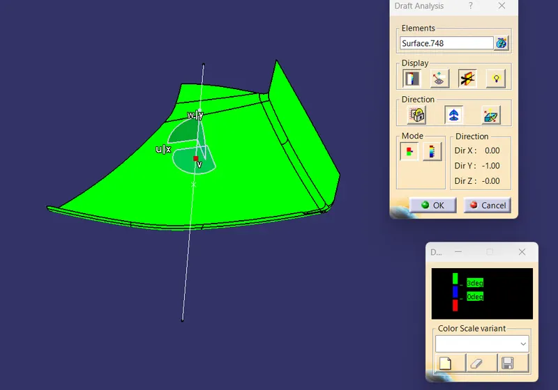
so class A surface draft is cleared so we move further to create a class B surface.
Creation of class B surface
- offset the class A surface to 2.5 mm
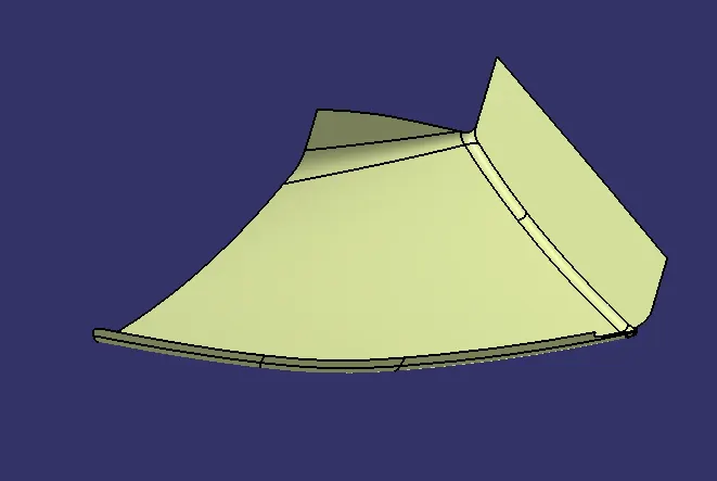
Creation of Class C Surfaces:
To create the class C surface concerning the boundary of the class A surface, I used the sweep command. Initially, I extracted the boundary of the class A surface with tangent continuity, and I sweep the extracted boundary concerning the surface at 93deg (for draft angle) for 5mm to intersect properly with the class B surface. Once we sweep all the surface boundaries of class A, extrapolate the sweeped surfaces until both surfaces got intersected properly, and trim them to remove extended extrapolated surfaces to get a proper sweep boundary throughout the entire surface.
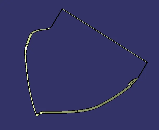
Now, join both class A and sweep boundary to get the complete class C surface
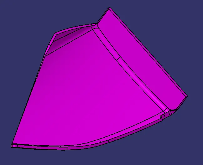
Now, unhide the class B and class C surfaces. Check whether all the sides of class B and Class C surfaces are intersecting properly with each other, to get a closed surface by trimming class B and class C surfaces. If the class B and class C sides are not intersected properly, we need to extrapolate the sides of the class B surface which are not intersecting with the class C surface. Now, check class B and class C surface By interseting tool whether all the sides are intersecting or not with each other. Once the surfaces are intersecting properly trim them together to get a closed surface.
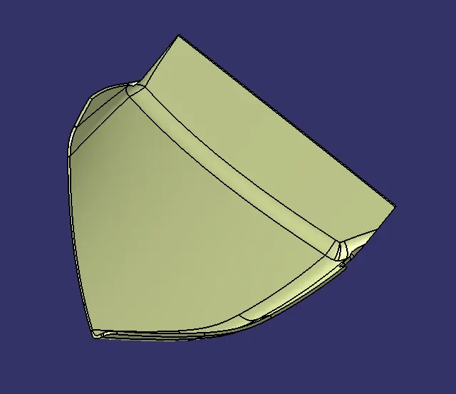
Now we have check the our bottle holder fully closed or not by using boundray command.
finally ourBottle holder is obatained.
Creating a solid body by using a closed surface :
To create soild body firstly switch to part body work bench and use close surface command to soildify the surface body.
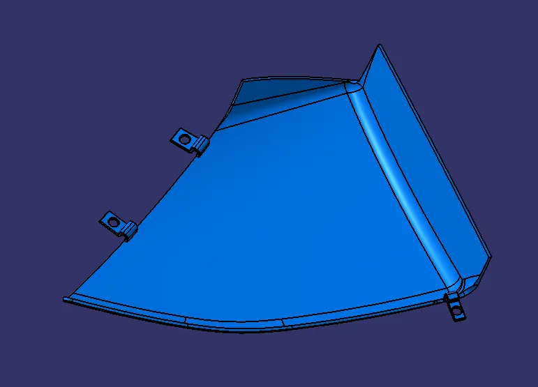
Now i created all the four surfaces to part body .
B side features creation:
Dog house:
- Extact the bsae surface.
- create a point and create plane normal to the curve
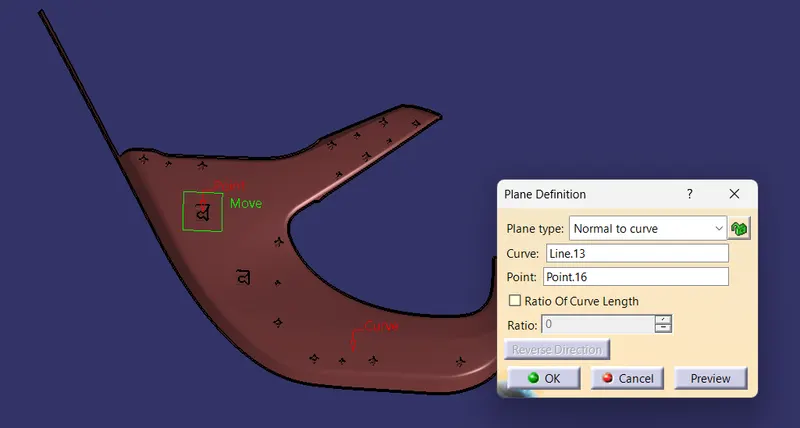
- Draw the sketch and do extrue and trim the surface for the required shape of the dimensions
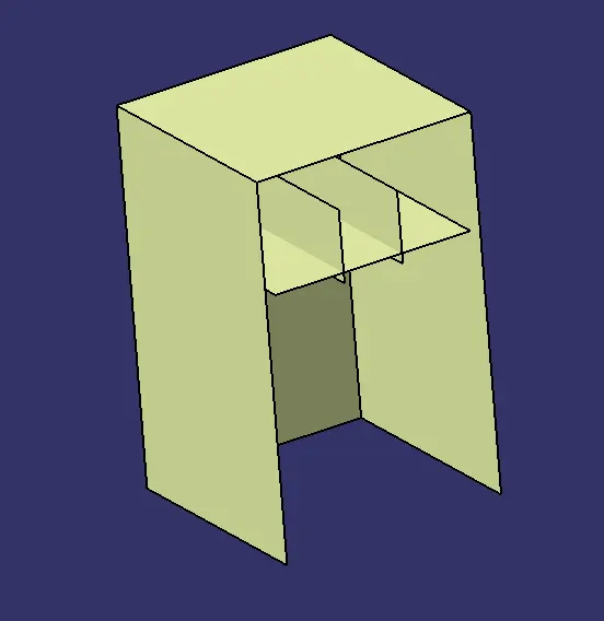
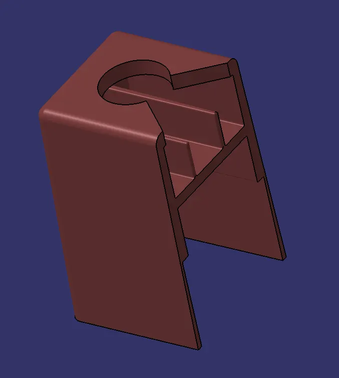
After create the surface we thicken the surface and gave fillet to the edges for inner and outside of the dog house.
So that our dog house is created and draft for the outside and inner surface 0.45 deg.
Heat Stakes:
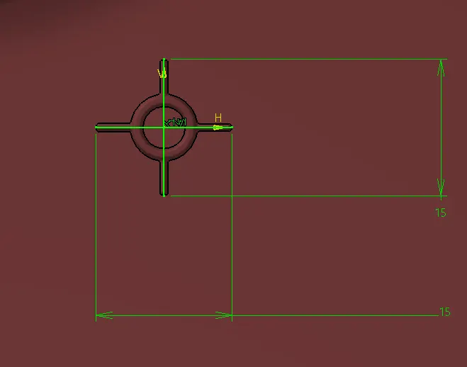
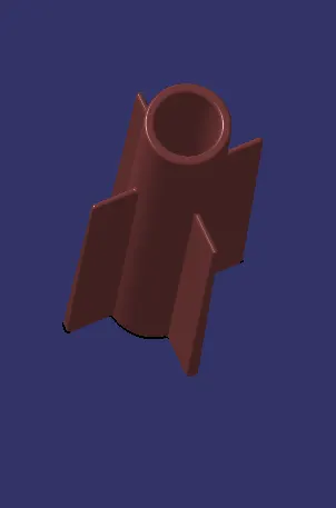
Create a sketch for the heat stake.
Pad it to the required distance.
Draft it on both sides
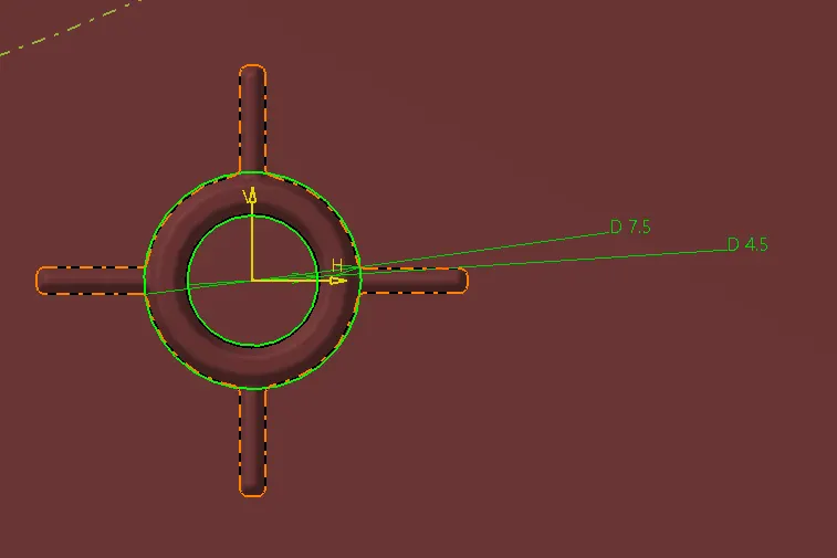
RIBS NEAR HEAT STAKE
Create a positioned sketch on the same plane where the heat stake sketch is done.
Pad it to the required dimension and thick it to 1 mm.
Draft angle of 0.5 degree is given.
Fillet the edges .
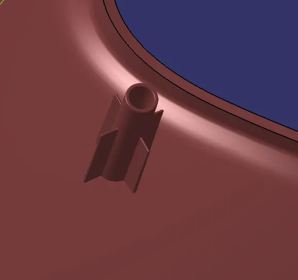
Union trim both the heat stake and ribs with the lower substrate.
Like this the heat stakes are created on the flange of other side of the door arm rest.
FLANGE CREATION:
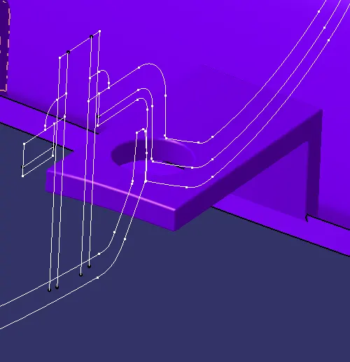
with the reference of the master section.
Extract the surface and parallel curve to 2.5 mm and extrude all the curve and trim and thicken the surface and gave fillets to the surfaces.
Door Arm Rest
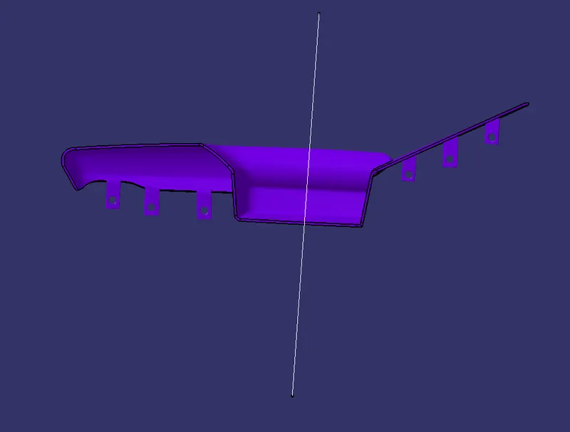
Map POcket:
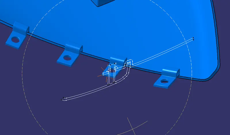
Bottle holder:
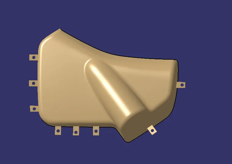
So that i deside and make the flange were thery are required.
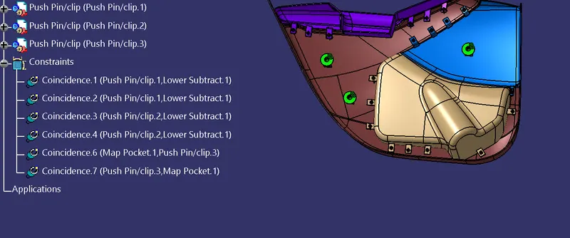
Now switch to assembly work bench and import the push clip and by using coincide with dog house.
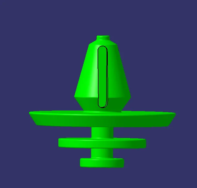
Final result: