Design of Shallow Foundation (Isolated Footings)
Design of Shallow Foundation (Isolated Footings)
Design a square footing for a column size of 400x400. The compression axial load for the load combination of (1.5 DL + 1.5 LL) is 2000 KN. The safe soil bearing capacity is 150 KN/m2 at a depth of 2 metres below E.G.L. Participants are free to go for either a tapered or stepped footing. Besides the total axial load, also account for the self-weight of the footing and soil above it. Assume M25 concrete grade. Do the following checks:
- If the gross bearing pressure under the footing is within safe bearing capacity
- Provide sufficient depth and longitudinal steel for resisting bending and shear
- Sufficient anchorage for column steel into the footing
- If the bearing pressure at column-footing joint is within 0.45 times the maximum concrete compressive strength
AIM: design of footing by manually ( size, shape and load ) according to soil condition
Introduction:
- Footings and other foundation units transfer loads from the structure to the soil or rock supporting the structure.
- The distribution of soil pressure under a footing is a function of the type of soil and the relative rigidity of the soil and the foundation pad.
- Most common types of footings used are:
- Strip or wall footing
- Spread footing
- Stepped footing
- Tapered footing
- Pile cap
- Combined footing
- Mat or raft footing.
Steps:
steps involved in footing design
- 1) calculation of gross soil pressure for footing area
- 2) calculation of net soil pressure for flexure and shear design
- 3) initial depth of footing calculation
- 4) flexural reinforcement calculation
- 5) one way shear check
- 6) two way shear check
1) calculation of gross soil pressure for footing area
unfactored load with surcharge + self weight of footing/ allowable soil pressure
= (2000/1.5X1.1) / 150 = 9.78 m^2
assuming we have square footing
= 3.12 meter side footing
so, consider 3.2 meter sided footing
2) calculation of net soil pressure for flexure and shear design
factored load / actual area of footing
= 2000 / (3.2X3.2)
Pn= 195.3 Kn/m^2
3) initial depth of footing calculation
assume depth of footing 500 mm and checking it for bearing stress as per IS 456:2000 clause 34.4
√(footing base bearing area / loaded area ) < 2
so, permissible bearing stress 0.45 X FCK = 11.25 N/mm^2
permissible bearing stress multiplied with area factored 11.2.5 X 2 = 22.5 N/mm^2
Actual bearing stress at column base
(2000X1000) / (400X400) = 12.5KN/mm^2
12.5 N/mm^2 actual stress is less than permissible 22.5 n?mm^2 hence ok
we can proceed with 500mm depth footing for further design checks
If we assume 50mm cover for footing, the effective depth (d) shall be taken as 450 mm
4) flexural reinforcement calculation
conversion of net pressure into uniformly distributred load
= 195.3 X 3.2 = 625 Kn/m
bending moment due to UDL over a cantilever section
= wL^2/2 = 625 X 1.6 X 1.6 /2
M = 800 Knm
Reinforcement calculation as per IS 456:2000 Annex G
Mu = 0.87 fy An d ( 1 - An Fy/bd Fck )
Assume Fy = 500 n/mm^2 in result Ast required = 4350 mm^2
If we provide 16mm dia rebar at 125 mm spacing the actual rebar provided = 3200/125 X 201
Ast provided = 5146 mm^
5) one way shear check
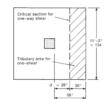
shear force in the one way shaded area
= 0.95 X 3.2 X 195.3 = 593.7 KN
Design shear stress at one way cut face
Ty = 593.7 X 1000 / ( 3200X450) = 0.412 N/mm^2
Shear stress capacity of section as per IS 456:2000 Table-19 ( include rebar )
= 0.425 N/mm^2
Design shear stress is less than shear capcity
Hence Okay
6) two way shear check
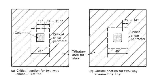
shear force in the two way sheaded area
= ( 3.2 X 3.2) - (0.85X0.85) X 195.3 = 1859 KN
Design shear stress at Two way cut face
Tv + 1859 X 1000 / ( 3400X450) = 1.215 N/mm^2
shear stress capacity of section as per IS 456:200 clause 31.6.3.1
= 0.25 X √Fck = 1.25 N/mm^2
Design shear stress is less than shear capacity Hence okay
Result:
design of footing done successfully
drawing of footing is attatch to the challange