Creating 3D Isometric view of various structural elements in AutoCAD
Creating 3D Isometric view of various structural elements in AutoCAD
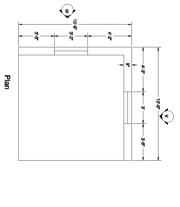
1) AIM: Create a 3D Isometric View of the building with plan and elevation given.
Introduction: create a 3D Isometric view by using 3D modelling in autocad using drafting and editing command like line, rectangle, extrude, offset etc
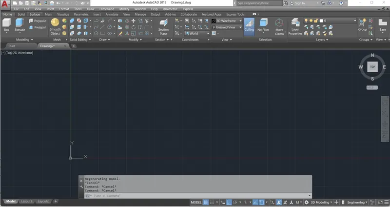
Procedure: Step1) auto cad 3d startup
open the auto cad as imperical
then go for 3d modeliing from workspace switching oprtion
then go for plan command and go with top view
and set unit as engineering for feet inch
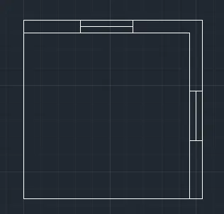
step 2nd) draw a plan using line & rectangle command
first we go for rectangle command from command box
then specify first point and draw rectangle of size 10'9" by 10'9"
then by using OFFSET command take offset of 9" from two side of wall
or we draw a wall thickness of 9" by using line command and trim the extra part
then by using LINE command we create or draw a window of size 3" for section A at a distance of 3'6" from right side of plan
then same by using line command we draw a window of size 3'2" from 4'2" of right side of section B
and show panel of window at mid of wiondow using line command
then draw 6" top slab and 4" bottom style or flooring to plan
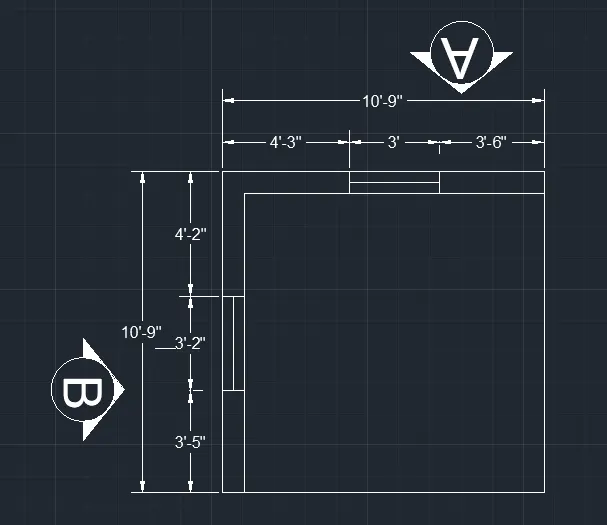
step 3rd) annotation
by using DIM command or from annotation take dimension command
and from choose linear set primery unit as engineering
and fit of 20 unit with precious 0.0 and shows all linear dimension
and then go for text command from annotation bar
and set the setting with format as ariel and give required text
step 4th) make the plan 3D
make a plan 3D by using XTRUDE command
and make a elevation 1 and elevation 2 as per given size
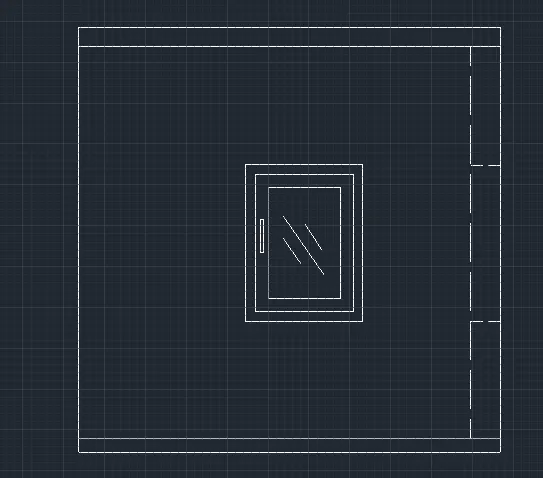
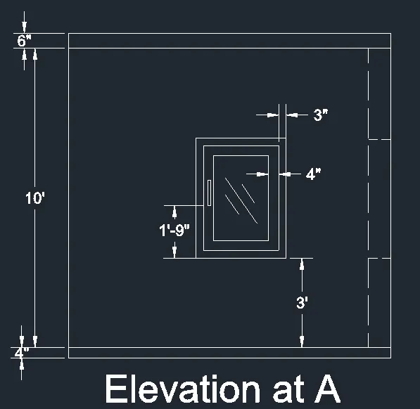
for 1st elevation A
subtract window part from wall by using subtract botton or command
then by setting the UCS draw a rectangle using REC command on window face extrude it of 9" as wall thickness
and offset it by offseting command @3",4" respectively then draw lock pannel or handle at height of 1'9" from sill level
step 5rd) annotation
by using DIM command or from annotation take dimension command
and from choose linear set primery unit as engineering
and fit of 20 unit with precious 0.0 and shows all linear dimension
and then go for text command from annotation bar
and set the setting with format as ariel and give required text
step6 ) draw elevation at B
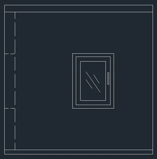
go to section B side from navigation bar
subtract window part from wall by using subtract botton or command
then by setting the UCS draw a rectangle using REC command on window face extrude it of 9" as wall thickness
and offset it by offseting command @3",4" respectively then draw lock pannel or handle at height of 1'9" from sill level
step 7) annotation
by using DIM command or from annotation take dimension command
and from choose linear set primery unit as engineering
and fit of 20 unit with precious 0.0 and shows all linear dimension
and then go for text command from annotation bar
and set the setting with format as ariel and give required text
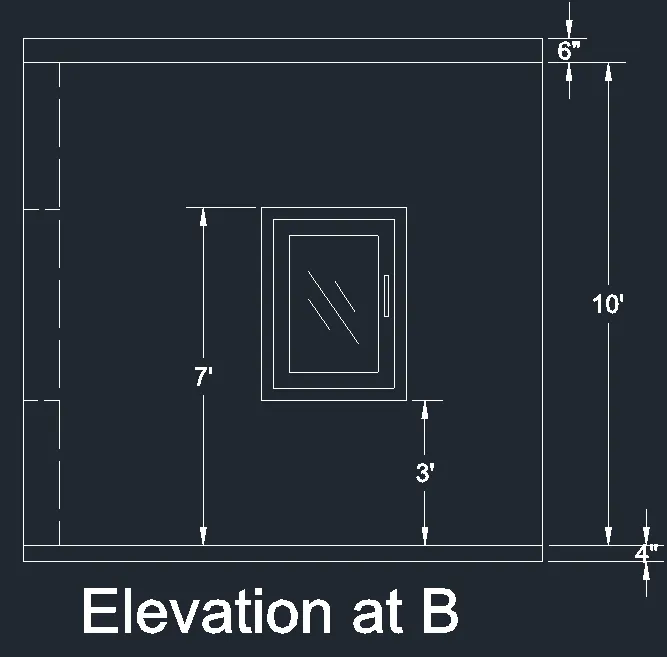
Result: we draw a plan in 3D modelling using variou drafting command in auto cad 3D and showing plan and elevation of it
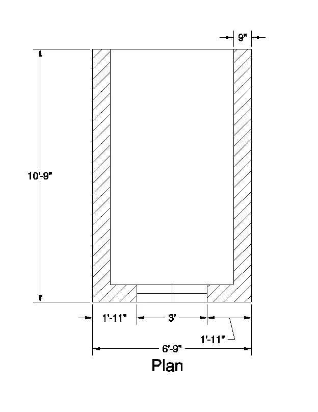
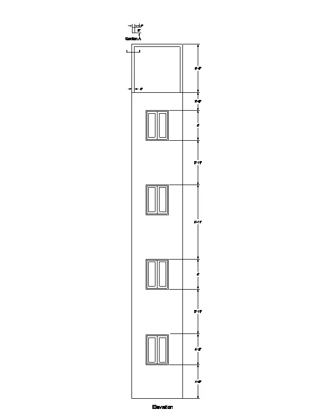
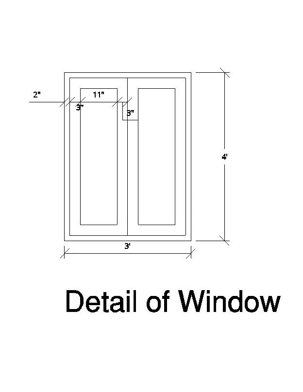
2) AIM: Create the 3D View of the Building Façade as given in the plan and elevation. Also, see the detail of the window.
Introduction: draw a 3D of building using autocad 3D using various drafting and view command
Procedure: Step1) auto cad 3d startup
open the auto cad as imperical
then go for 3d modeliing from workspace switching oprtion
then go for plan command and go with top view
and set unit as engineering for feet inch
step2) creating plan
from top view and plan command set ucs x,y and z
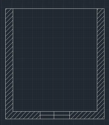
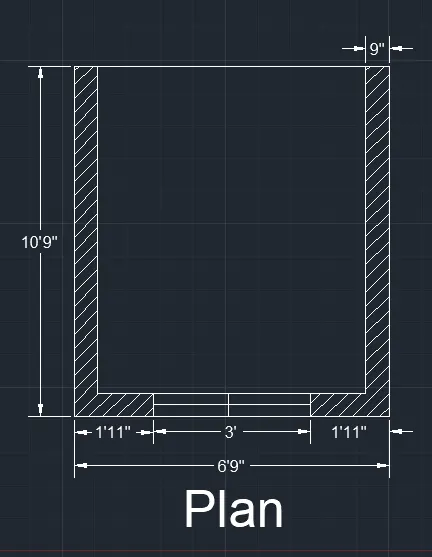
then draw a plan using line and rectangle command
take rectangle command and draw a rectangle of size 6'9" X 10'9" by setting origion point
then take offset command OFFSET and offset of 9" as wall thickness
remove unwanted lines using TRIM command
then draw a window panel using line command as size of 3' at mid of bottom wall and showing panels by drawing cross line
step 3) annotation
by using DIM command or from annotation take dimension command
and from choose linear set primery unit as engineering
and fit of 20 unit with precious 0.0 and shows all linear dimension
and then go for text command from annotation bar
and set the setting with format as ariel and give required text
step 4th) make the plan 3D
make a plan 3D by using XTRUDE command
extrude plan by height 47'7"
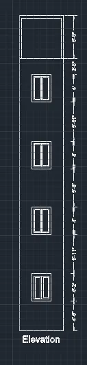
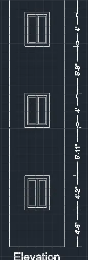
and make a elevation elevation
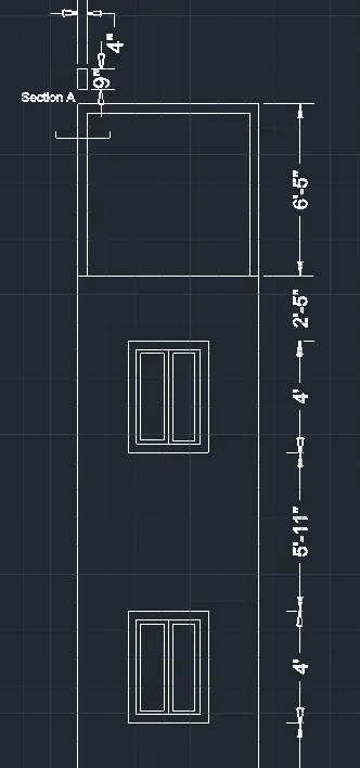
for elevation A
subtract window part from wall by using subtract botton or command
and set windows at perticular locations
then by setting the UCS draw a rectangle using REC command on window face extrude it of 9" as wall thickness
and offset it by offseting command @3",4" respectively then draw lock pannel

step 5) annotation
by using DIM command or from annotation take dimension command
and from choose linear set primery unit as engineering
and fit of 20 unit with precious 0.0 and shows all linear dimension
and then go for text command from annotation bar
and set the setting with format as ariel and give required text
step6) Dtailed of window
copy the window from elevation
by using DIM command or from annotation take dimension command
and from choose linear set primery unit as engineering
and fit of 20 unit with precious 0.0 and shows all linear dimension
and then go for text command from annotation bar
and set the setting with format as ariel and give required text
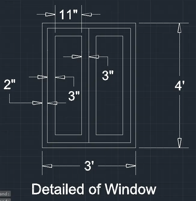
Result: we create a plan, Elavtion and window detailes using auto cad 3D by using drafting and anotating commands
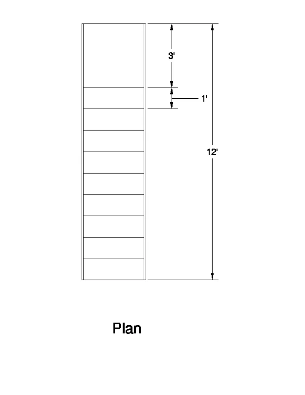
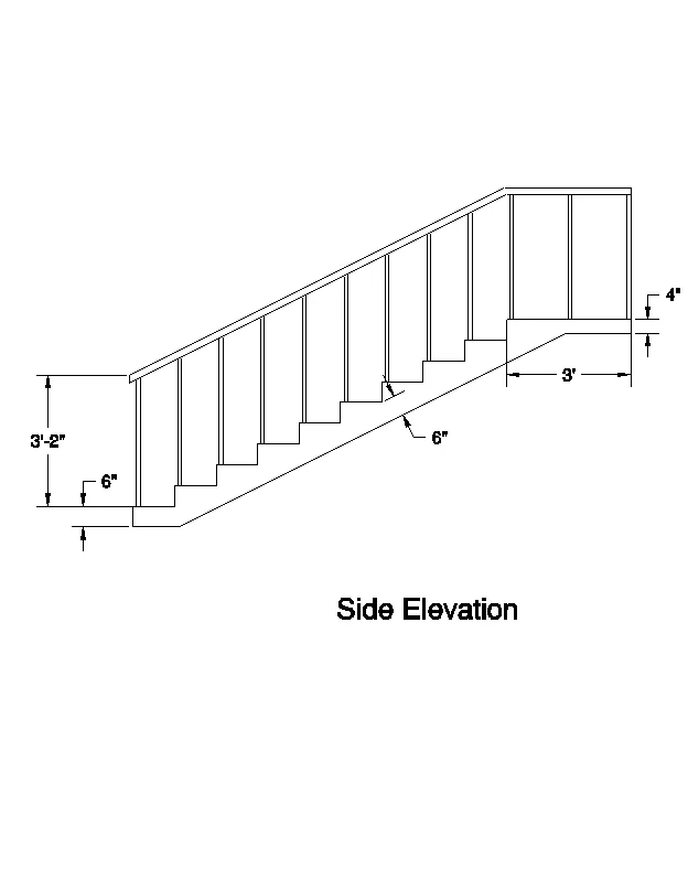
3) AIM: Create the ismoteric 3d view of a stair with railing as shown in the plan and elevation. Assume the size of the balustrades and the hand rails.
Introduction: draw a 3D view of single fight staircase using autocad 3D using various drafting and view command
Procedure: Step1) auto cad 3d startup
open the auto cad as imperical
then go for 3d modeliing from workspace switching oprtion
then go for plan command and go with top view
and set unit as engineering for feet inch
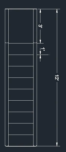
step2) plan of staircase
go for top view and draw a side plan of staircase
take line command as LINE and draw a line
select origine and draw a line vertically up at distance of 6" top for riser
and 1' size trade make same 9nos stairs of same size
and draw landing of 3' wide
after that draw a grill/ raling using SWEEP command
then draw west slab of 6" depth
and extrude the steps with 2.5' height
then go for top view we get plan of staircase
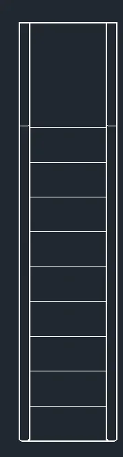
step 3) annotation
by using DIM command or from annotation take dimension command
and from choose linear set primery unit as engineering
and fit of 20 unit with precious 0.0 and shows all linear dimension
and then go for text command from annotation bar
and set the setting with format as ariel and give required text
step4) solid elevation
then go for solid elevation which we draw first
go with help of navigation bar or 3Dorbit command
then, by using DIM command or from annotation take dimension command
and from choose linear set primery unit as engineering
and fit of 20 unit with precious 0.0 and shows all linear dimension
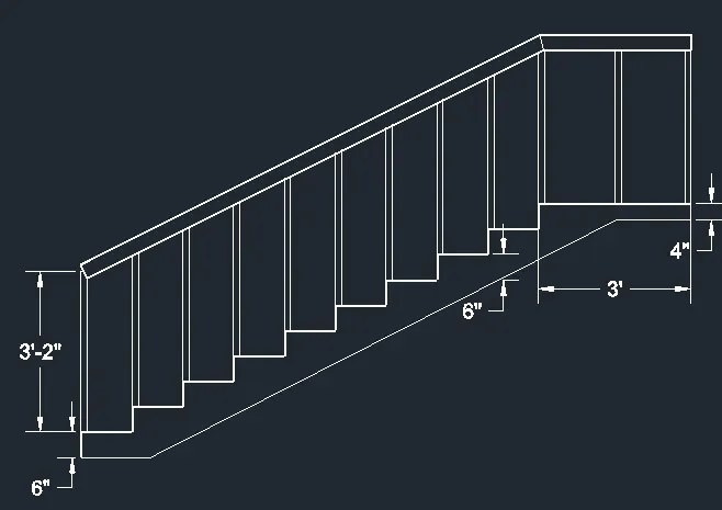
result: we draw a staircase plan and elevation by using auto cad 3D with various drafting and anotating commands
4) AIM: Create the 3D view of a Wall with spread footing . Create the Door opening only. Assume the size of the parpaet and the coping. Also, create a rendered view of the model with materials as of your choice.
Procedure: Step1) auto cad 3d startup
open the auto cad as imperical
then go for 3d modeliing from workspace switching oprtion
then go for plan command and go with top view
and set unit as engineering for feet inch
step2) plan
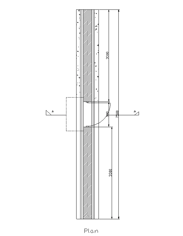
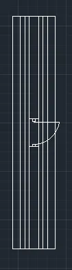
go for top view and draw a plan using rectangle or line command
take LINE command and draw a line by setting a origine point
draw a line uppward at a distance of 7500 unit then go right side of 300 mm as wall thciness
again go bottom with 7500mm and close the line and joint object using JOINT command
then go for OFFSET command and offset the command 2 times with distance 30mm each and as for step footing
then again go for offset command and offset of 50mm from last line for concrete presistral or for PCC of footing
then draw door at mid point on wall of size 900mm and show the door panrl using circle and line command
and trim unwanted lines using TRIM command
step3) hatches
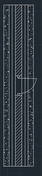
hatche the plan by using HATCH command
go to HATCH command and select wall section and go to ANS hatch for wall
take a hatch and put on wall and take size as 250 unit
then hatch for concrete
go to HATCH command and select concrete hatch
and put hatch in last offset as concrete hatch with 30 size of hatch
step 4) annotation
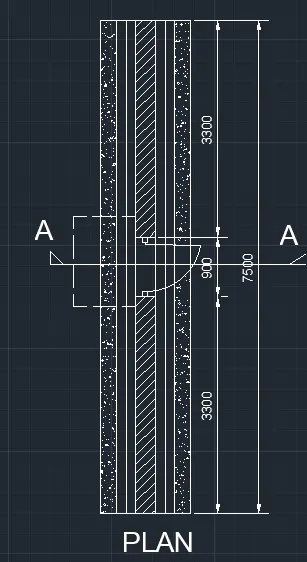
by using DIM command or from annotation take dimension command
and from choose linear set primery unit as engineering
and fit of 20 unit with precious 0.0 and shows all linear dimension
and then go for text command from annotation bar
and set the setting with format as ariel and give required text
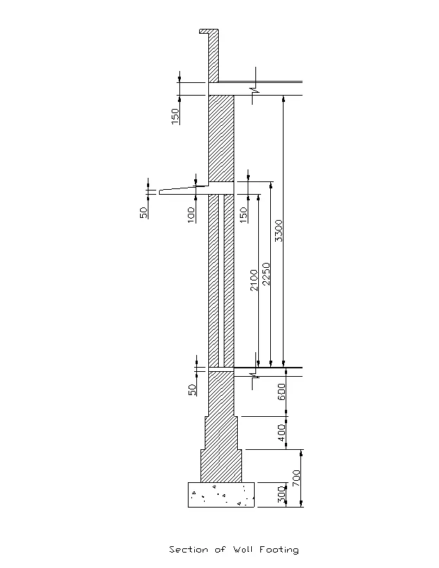
step5) make a 3D
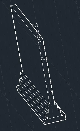
select a object and rotate the object using 3D rotate command
and by using EXTRUDE command extrude the drawing or object by given size
300,400,400,600,2100 like that respectively like
step6) then draw window
by substracting the window section draw a window and lintel
by using SUBTRACT commmand
and draw chajja as per given
and give hatching
hatche the plan by using HATCH command
go to HATCH command and select wall section and go to ANS hatch for wall
take a hatch and put on wall and take size as 250 unit
then hatch for concrete
go to HATCH command and select concrete hatch
and put hatch in last offset as concrete hatch with 30 size of hatch
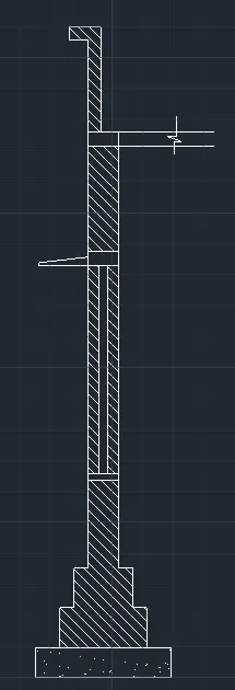
step 7) annotation
by using DIM command or from annotation take dimension command
and from choose linear set primery unit as engineering
and fit of 20 unit with precious 0.0 and shows all linear dimension
and then go for text command from annotation bar
and set the setting with format as ariel and give required text
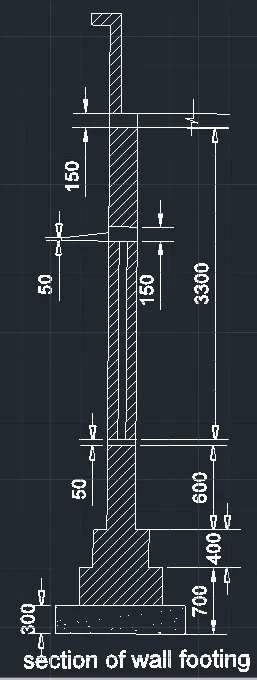
Result: we draw a wall plan and section of wall with footing using auto cad 3D by using drafting and anotating commands