Creating Levels, Grids, Layout and model elements for a residential unit using REVIT
Q1) What is BIM? Summarize the features of BIM and benefits of using BIM over 2D CAD tools
AIM: What is BIM? Summarize the features of BIM and benefits of using BIM over 2D CAD tools
ANS)
BIM is a Building Information and Modelling is a visual representation of the physical and functional characteristics of a facility from inception onwards. as such, it serves as a shared Information repository for collaboration throughout a facility's life cycle.
1) BIM is an acronym for building information modelling or management
2) it is a highly collaborative process that allows architext, engineersetc etc to plan, design and construct building within one 3D model
3) This data allows govertments, municipalties and property managers to make informed decisions based on derivede from the model.
Features of BIM are:
- Easy access to information: BIM is a physical representation of the phisical and functional characteristics of the building process, that provides every minute detail of the project
- Making the process more expressive: one can easily access the right information at the right time that provides a reliable basis for decision making during a structures entire lifecycle
- Comprehensive view of the project: BMI design tool allow you to obtain various views from a building and produced heigh quality accurate drawing
Benefits of BIM are:
- Complete Representation: all component models in 3D BIM software contains real world information about that component
- Instant Updates : if you were to place a wall within a BMI model that wall would atomatically include information about it such at its length width within littel no additional input from this users
- Time constraint: requires less time compare to other softwars for drawing 3D
- Resource tracking: facility to location for current resourse tracking
Q2) Understand the concept of Categories, Families, Elements, Instances in Revit. Go to Insert Tab, choose a category. Pick a family and element. Understand the instances and insert it to Revit model
AIM: Understand the concept of Categories, Families, Elements, Instances in Revit. Go to Insert Tab, choose a category. Pick a family and element. Understand the instances and insert it to Revit model
Procedure:
1) Categories:
a) classification of families,for ex, doors,curtain walls,furniture and electrical etc
b) families are grouped and sorted by category in the content libraries and in the project browser
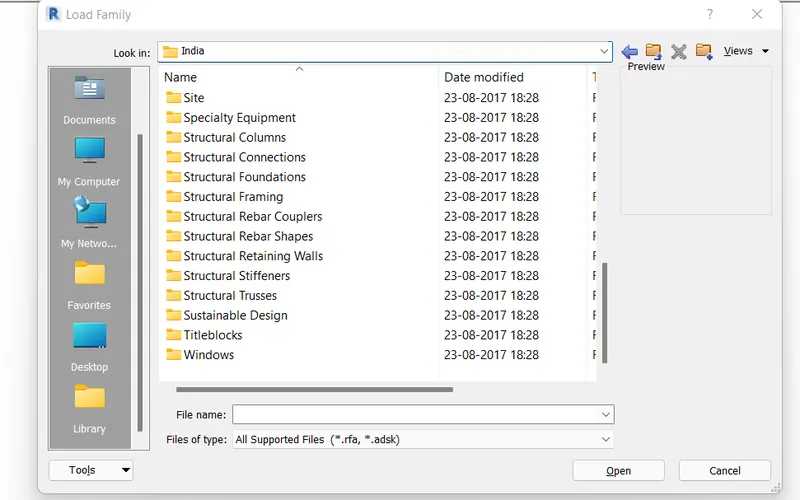
we got categories from load family option from components
2) Families:
a) A family is a group of element with a common set of properties,called parameters, and a related graphical representation.
b) Diffrent elements belonging to a family may have diffrent value for some or all of their parameters, but the set of parameters is the same
c) all of the elements in revit are families
3) Elements:
a) Elements are the building block of a 3D model.
b) they represnt the real-world component that a designer adds to the model
c) some elements such as wall, window, column and beam are 3d and present in all view
d) other elements such as tags,dimensions or ather annotation appears only in the view in which they are placed
4) Instances:
a) Intances are individual graphical/geometric element placed in revit model eg a single wall, or a single door, or any other single element
b) as a subset of revit elements instance inherting a series of parameters from their category and type and might have instant parameter as well that only belongs to that single instants
Q3) Setting up a Project – Open a project file with architectural template. Save the file with appropriate name. Set up the project units to Imperial / Metric based on your convenience of modelling. Complete the project information under Manage tab. Set up the maximum backups for project file to 3
AIM: Setting up a Project in revit 2018
Introduction: for setting a project. we need to select the architectural templete for modelling the architectural plan
when we save the file with appropriate name the name will be save in perticular folder
then set the unit of sheet and fill all project information of project
Procedure:
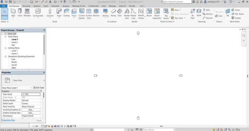
1) Open a Project with Architectural Templet
open the autodesk Revit 2018
thats type of window are open on screen
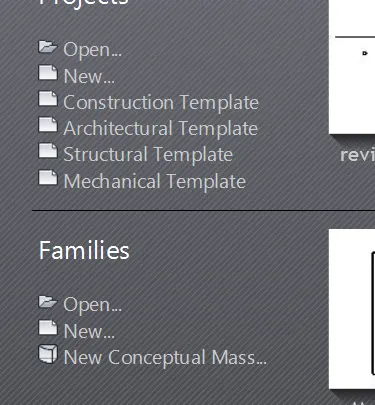
then select architectural templet
so the project scape in architectural template are open on screen like that
2) Save the file with appropiate name
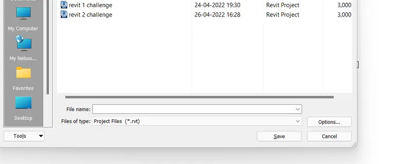
go to file toolbar located on left top on screen
then choose the save option
and give location where want to save
with name as ravit 2 challenge and press ok our file is save with same name
3) Set up the project units to Imperial / Metric based on your convenience of modelling.
go to unit command
press UN on screen OR go to manage tab and choose project unit option on screen
then choose a option where you change the unit
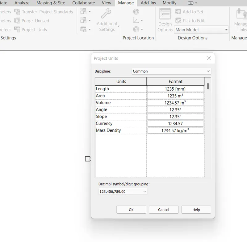
suppose we take length option
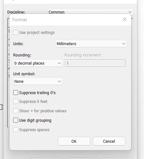
then we open the screen as mention below
in that we change the units as metric
4) Complete the project information under Manage tab
go to manage tab
choose a project information option

then click on that option
we tress out new window for inserting all information regarding project
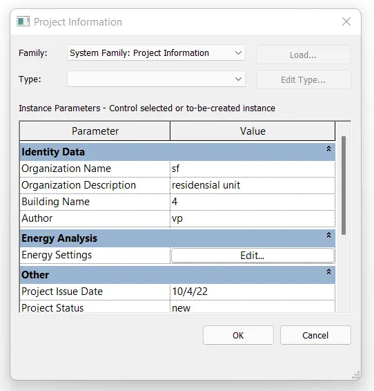
fill all the inforamation like, organization name, organization Description, Building name, project issue date, project status and owner etc. and press ok
5) Set up the maximum backups for project file to 3
go to file toolbar located top left corner of screen
then go for save as option in file toolbar
select on project option
then thats type of screen are opened
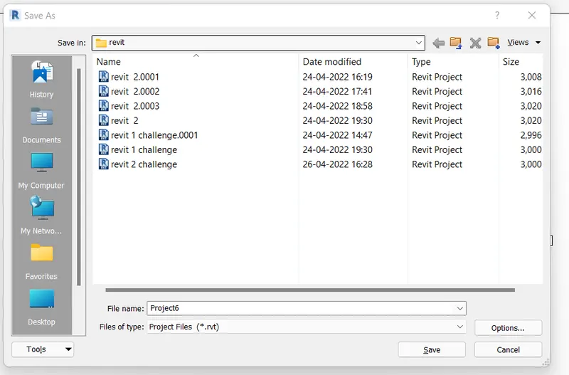
click on option tab situated below
set 3 as maximum for backup file
and press ok our file is backped 3 times
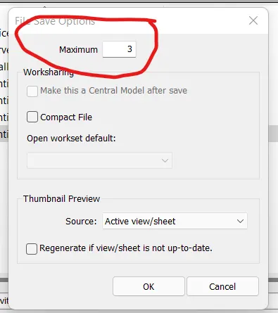
Result: Setting up a project is done successfully in the revit in proper manner
Q4) Understand the concept of Levels and Grids. Follow the naming and conventions. Create the following Levels: ( Convert to metric equivalents if metric is your units)
Ground Floor @ 0’
First Floor @ 10’
Second Floor @ 20’
Roof @ 30’
Grids Transverse Grids A, B,C,D, E @ 10’ spacing
Longitudinal Grids from 1 to 10 @ 20’ spacing
AIM: creates a grid with given levels
Introduction: Grids lines are finite planes, we can drag their extents in elevation views so that they do not intersect level lines
Procedure:
1) Set up the project units to Imperial
go to unit command
press UN on screen OR go to manage tab and choose project unit option on screen
then choose a option where you change the unit
suppose we take length option
then we open the screen as mention below
in that we change the units as metric
2) create the levels
go to elavation view as east from project browser
then we show the screen like this
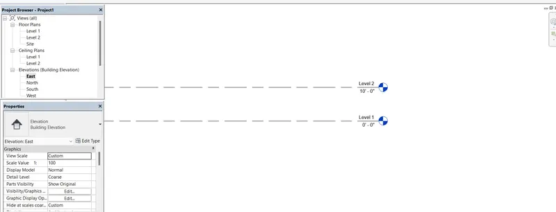
then go to structure tab then go on datum bar
and select the level option

then select pin from modify and set otion on 10'
and set the two more levels on 10' to make four diffrent levels on 10' each
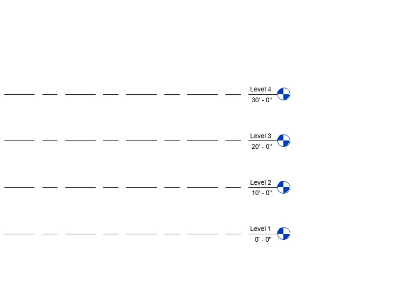
3) rename the level
rename the level by double click on level name
name it as ground,first,second and roof
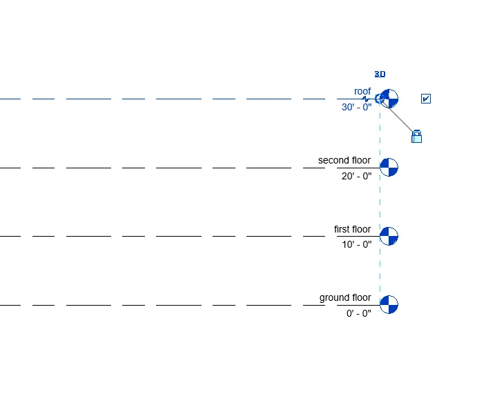
4) Grids Transverse Grids A, B,C,D, E @ 10’ spacing Longitudinal Grids from 1 to 10 @ 20’ spacing
go on architectural tab
and select grid option from datum

then select line from modify for draw
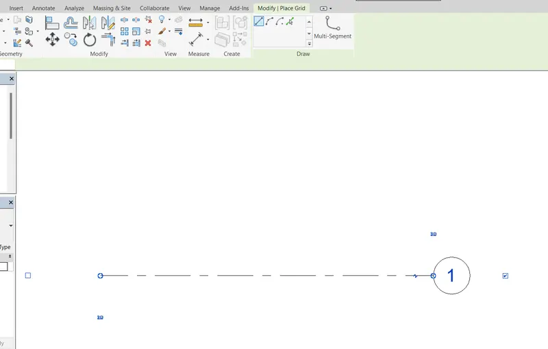
then again select grid option from architectural
and select pick line from modify
set offset as 10'
and draw or make 3 mode lines from last refrence line
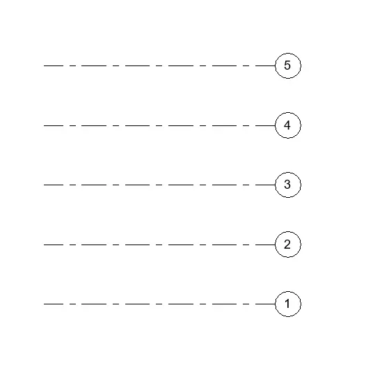
then rename the grid
by double clincking on number 1,2,3,4,5 as A,B,C.D,E and press enter
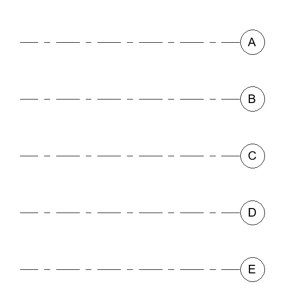
5) Longitudinal Grids from 1 to 10 @ 20’ spacing
go on architectural tab
and select grid option from datum
then select line from modify for draw
and draw longitudinal grid
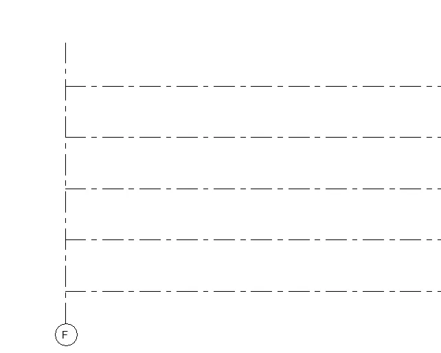
then again select grid option from architectural
and select pick line from modify
set offset as 20'
and draw or make10 more lines from last refrence line towards left right
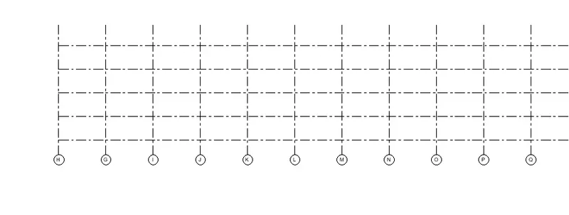
then rename the grid
by double clincking on number as 1 to 10
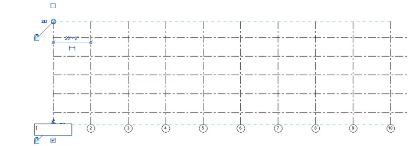
Result: the levels and grid lines are drawn successfully in the revit with proper mann
Q5) 3D modelling of residential unit – From looking at your house / or a place you aspire. Create a conceptual layout of the residential unit. You can measure using a tape or
you can access your residential plan to create a similar layout.
AIM: 3D modelling of residential unit – From looking at your house / or a place you aspire.
Introduction: make a moddel or layout as approprite size with doors, windows of Residential unit
Procedure:
1) oprn the revit 2018 and select new project
select Architectural Templet
thats type of window are open on screen
then select architectural templet
so the project scape in architectural template are open on screen like that
2) draw a residential layout
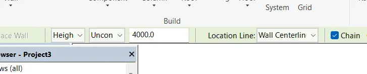
select floor plan from property
click on wall and select architectural wall option
then go to height and take height as 400mm
and selct wall type as generic 200mm
and draw a layout of approx 7000mmX 8000mm
and selct wall type as generic 200mm
and draw a layout of approx 9000mmX 8000mm
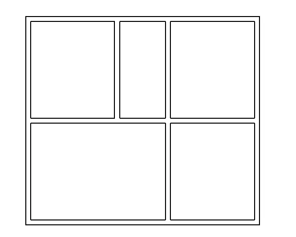
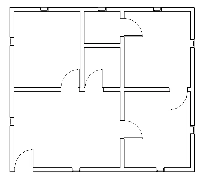
then from architecture select door and window option
and put door window where it needed
as shown in fig
next change the residential layout plan to the 3D view as shown in below with shaded visual
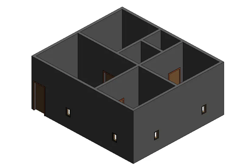
Result: the conceptual layout of the residential unit is created successfully in the revit
Q6) In the layout created draft the level of details you are planning to include – Dimensions of room, components you plan to add in the residential unit
AIM: In the layout created draft the level of details you are planning to include – Dimensions of room, components you plan to add in the residential unit
Introduction: Dimensioned the layout using linear dim for better understanding
Procedure:
go to annotation command
then select Linear dimension option from dimension tab

after choosing linear option
go to object and select exterio of wall to measure total external dim
and for internal dim measure inter to inter face of wall
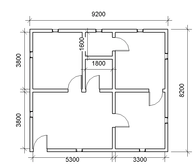
Result: The level of details which includes dimension of room
Q7) Identify the residential model elements such as Door, Windows, Tables, Chair, Couch, Bed, Lamps from the library and insert them to the model . Save the project for use
AIM: Identify the residential model elements such as Door, Windows, Tables, Chair, Couch, Bed, Lamps from the library and insert them to the model
Introduction: load or add components like door,chair,window,table, bed etc from load family
Procedure:
you have a existing plan and we have add residential unit on it
so go in archtectural choose COMPONENT option from it
click on that and choose and place component
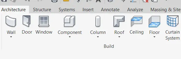
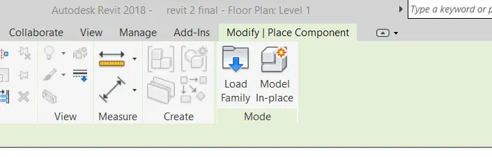
then select load family option from modify/place component
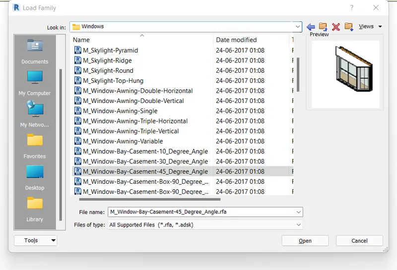
then you can come on files in that go to libraries option
and select india or we can choose any of them which we required
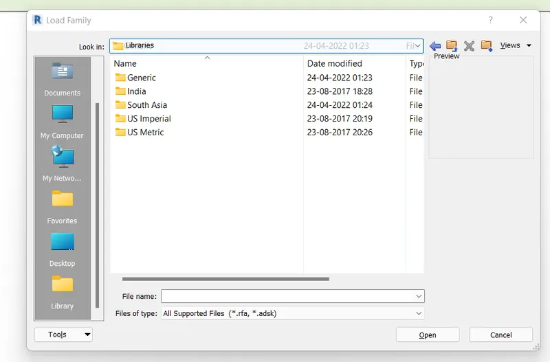
suppose we add window on our plan as unit
so click on window from india and open it
then choose window we want
in our case we take M-window-Bay-Casement_45-Degree-angle
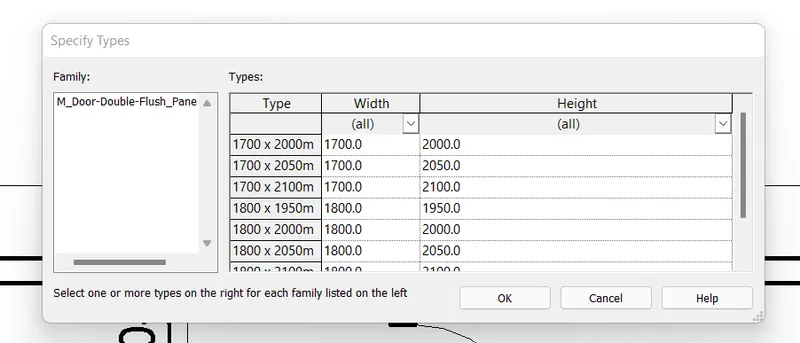
and open it then select size we want and press ok
then take same others residential unit like bed,chair,table
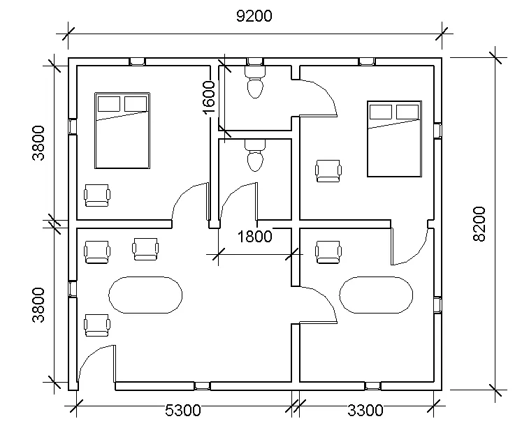
The all model elements are inserted successfully and the layout plan is turned to diffrent views
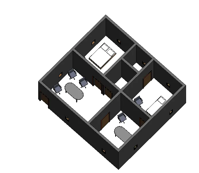
Result: Residential model elements such as doors, window, chair , table, bed are added successfully