Introduction to REVIT concepts
Introduction to REVIT concepts
Q1) From the file menu, create a new project (Structural / Architectural / Construction template ) and name the project appropriately
AIM: From the file menu, create a new project (Structural / Architectural / Construction template ) and name the project appropriately
Introduction: create a architectural templet, for creating a project and save the file with revit 1 challenge
Procedure:
open the revit 2018
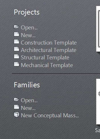
then from the model tab and click new file
then select archtectural templet and press ok
then we got workspace in architectural templet
then go to file menu save and give name as ravit 1 challenge
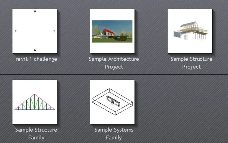
Result: we create a architectural templet file and name it as ravit 1 challenge

Q2) Save the new project file. Close and open using icons from file toolbar
AIM: Save the new project file. Close and open using icons from file toolbar
Inroduction: use the file toolbar for close and open the file by saving project file
Procedure:
op[en revit (2018) software
then from the model tab and click new file
then select archtectural templet and press ok
then we got workspace in architectural templet
then go to file toolbar and go for save option and click on it
and save the file with name as ravit 1 challenge,
then for closed the file
go to file toolbar located top left cornaer on screen
then go at last as closed option
then press ok so our file will closed
then for open the file
open the revit with any templet and
go to file tool bar
and press the open then click on file which want to open you
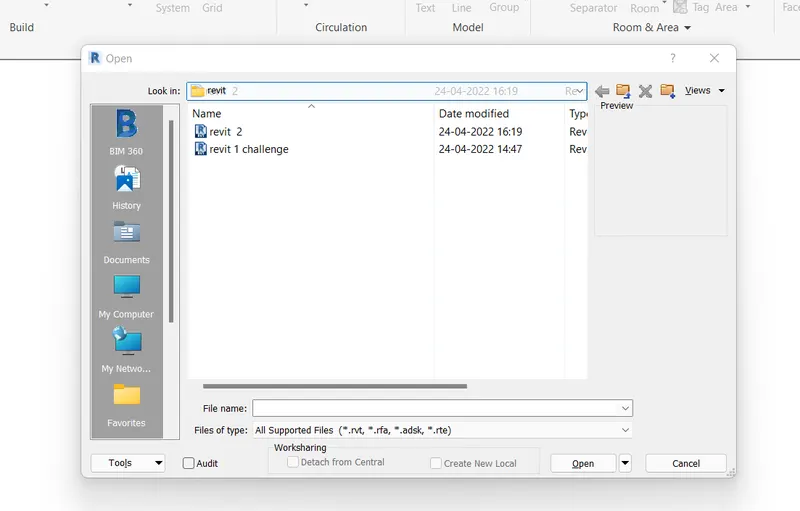
Result: we closed or open the save file using file toolbar
Q3) From the architecture/ structure toolbar familiarize with options to draw a wall. Create a rectangular layout of walls of about 40’-0” X 35’-0”
AIM: From the architecture/ structure toolbar familiarize with options to draw a wall. Create a rectangular layout of walls of about 40’-0” X 35’-0”
Introduction: use diffrent type of wall thickness, size and wall type in the architectural toolbar
Procedure:
open the revit 2018
then from the model tab and click new file
then select archtectural templet and press ok
then we got workspace in architectural templet,
then go to architectural
and select wall from
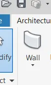
select wall option and select line from modify property option
then set origine point and draw a horizontal line of 40' length left to right
then draw verticall line from last point towards bottom of length 35'
then draw line from last line towards left at lengtrh of 40'
then draw line from last points towards up with 35' length vertically
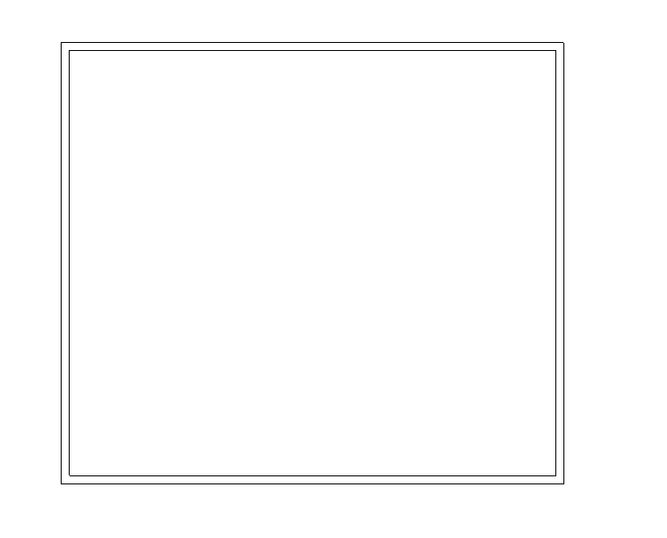
Result: we draw a wall rectangle size of 40'X35' usin architectural wall option
Q4) From the Annotate toolbar use the aligned option to add dimensions to the layout
AIM: use the alignede option to add dimension to the layout from the annotation toolbar
Introduction: in this we use the anotation toolbar to dimension the rectangular layout using the aligned option in the anotation toolbar
Procedure:
take a last example of rectangle of size 40'X35'
and dimension it using annotation aligned option
so go to annotation option from screen
and go to dim option and select aligned option from it
then select centerline of wall or object which we want meanserd
in our case is rectangle size wall take first point of centerlined of wall and other point same at centerline we got dimension of line
same do for other line
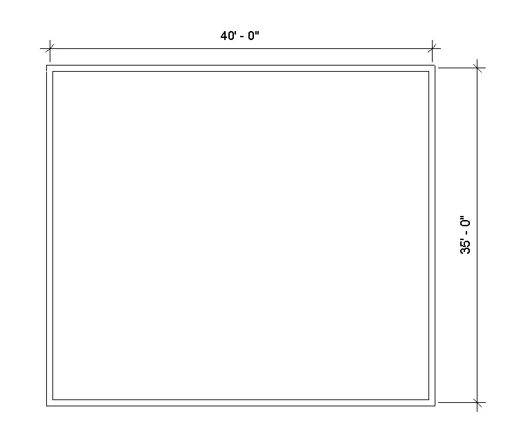
Result: we dimensioned (alligned) layout or wall rectangle using annotation tool are successfully
Q5) Use the properties browser to switch to different wall types
AIM: Use the properties browser to switch to different wall types
Introduction: in the property browser there will be diffrent wall sizes
Procedure:
go to property browser
from view>users interface>property browser
take a last example of rectangle of size 40'X35'
then selct left side vertical wall
and go to property browser on screen and click on basic wall
and change the wall type we want
here we change wall type generic 200 to generic 350mm
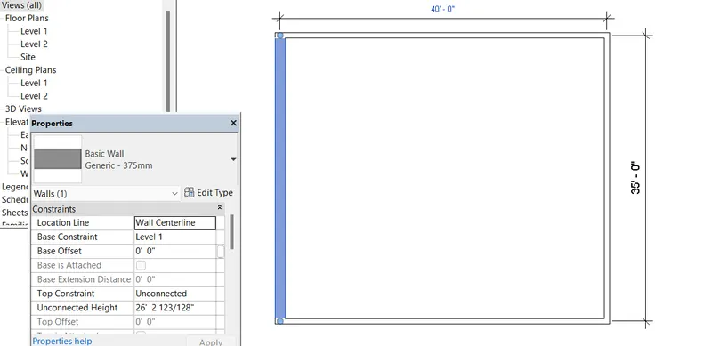
Result: we change or switch a line type generic 200 to generic 375mm by using property browser
Q6) Create a 3D view from the view toolbar and save the view with the appropriate name
AIM: Create a 3D view from the view toolbar and save the view with the appropriate name
Introduction: In the view toolbar we can see various option we take only select 3D view option
Procedure:
go to 3D (3d defalt view) from view bar
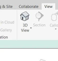
then go to view cube
right click on view cube
and select save view option
and seve view as V1 name
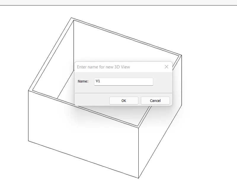
Result: we create a 3D view from view tab and save view from save view>view cube
Q7) Navigate through the 3D model using the view cube. Orbit/pan through the model layout created
AIM: Navigate through the 3D model using the view cube. Orbit/pan through the model layout created
Introduction: view cube is used to navigate the 3D model in any direction, orbit also used to navigate 3D model to any path and pan is used to navigate 3D model to th position
Procedure:
take last example of 3D model of wall rectangle
navigate it with help of view cube by clicking a direction on view cube
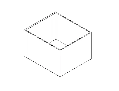
go on navigation bar located below view cube
if navigation bar are not available on screen then
go in view tab>user interface>navigation bar
navigation bar is come on our screen
then click on navigation bar
and in that we use the option like orbit/pan and walk, zoom
clickng on perticular tab like we use orbit then click on orbit tab in circle
and they work
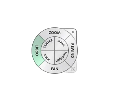
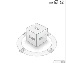
Result: we use navigation to orbit, pan and zoom 3D model, the three dimensional model is navigate using the view cube, orbit and pan holding them with the curser
Q8) Use the visibility settings option below to switch model to shaded, realistic, hidden lines options
AIM: Use the visibility settings option below to switch model to shaded, realistic, hidden lines options
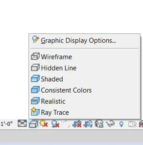
Introduction: using the visibility setting we can change the visibilty of model such as wireframe,hiddenline,shaded,consistent colour and realistict
Procedure:
go to bottom visual style hidden line option on screen
and click on you have various option of view style like
wireframe,hiddenline,shaded,consistent colour and realistict
then, just take a previous example of rectangle of size 40'X35'
click on shaded for shaded model
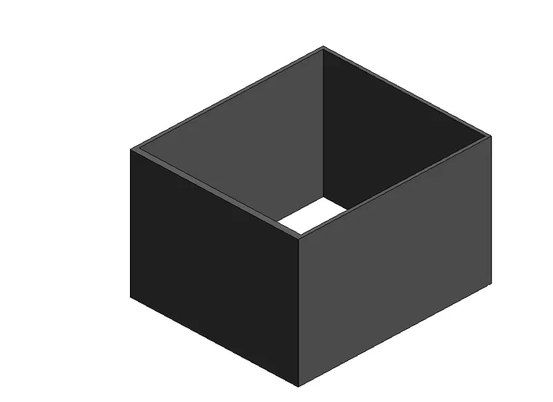
now
click on realistict for realistict module
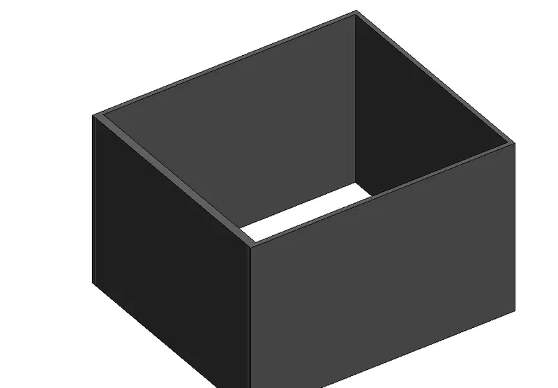
now
click on hidden line for hidden line module
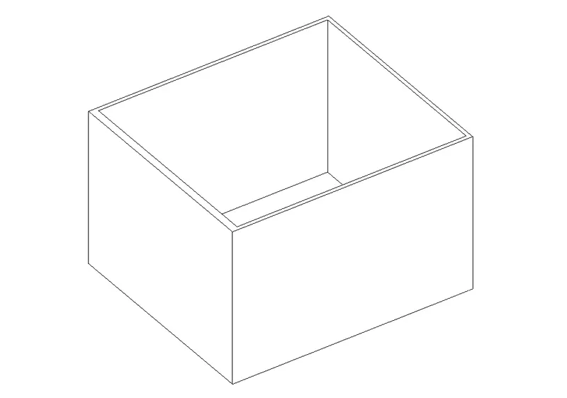
Result: we change the visibility ob object using visual style option like hidden line, shaded and realistict
9) Turn the sun path on and off to view shadings in the layout created
AIM: Turn the sun path on and off to view shadings in the layout created
Introduction: The sun moment is an important consideration when designing high performance buildings
Procedure:
go to bottom of screen on sun path option
click on that icon
and select the sun path on Or sun path off from it
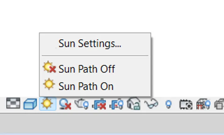
we make a sun path on from setting we get thats tipe of sun path
when sun path is on
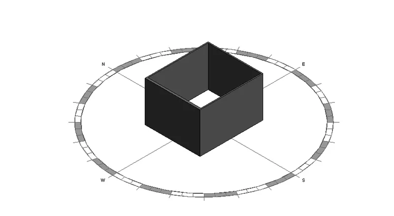
when sun path is off
and selecting sun path setting we can change the setting which we want requiored
Result: we changd the sun path on and sun path of from sun path option
Q10) Use the Manage toolbar to enter project settings, project name, and project issue date (choose according to your convenience)
AIM: Use the Manage toolbar to enter project settings, project name, and project issue date
Introduction: in manager tool bar we can see diffrent option for managing the layout
Procedure:
for entering settings, project name, and project issue date
then we can go to manage command which is shoen on our screen toolbar
then go to project information icon and click it
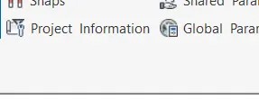
then we can change and enter the setting and name from that table
which we want to change
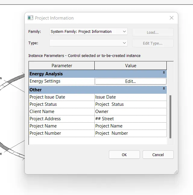
Result: Manage toolbar to enter project settings, project name, and project issue date from the project information icon which is located in manage option
Q11) What is the Analyze toolbar used in Revit? How it is beneficial for design and modeling
AIM: What is the Analyze toolbar used in Revit? How it is beneficial for design and modeling
ANS)
1) analyse toolbar helps you to perform analyse on our object, the boundry conditions enable you to define point line and area boundry conditions in an analytical model. it will verify the boundry conditions family types are loaded and assigned in your parametric features of the stryctural model, similarly we can apply point to a model to evalute the performance og building
2) similarly we can add and edit load cases to define the design standard suggested load case to a model we can combine diffrent load cases using load combination icon, it will enable to add and edit load combination for the analytical model. the main purpose of using the revit to evalute the sustanability of building that we modelling, so we will be intrested in evaluting the energy or energy optimization of the building that we are going to model so revit offers features such as it creats an energy models fromthe features we have modelled i our project than the energy analytical model based on the conceputual masses. the building elements, and the material that we use to construct the building and the quantity that are required to completion of project

Q12) What are the links that Revit supports to be linked to the model?
AIM: What are the links that Revit supports to be linked to the model?
ANS)
following are the links that revit support to be linked to the model
1) Link Revit:
this allows to link another revit model to the current revit model
2) Link IFC :
to link IFC file to current model to refrence it information for additional design work
3) Link CAD:
to link the 2D cad file to current revit file to create 3D by using revit
4) Manage Link
provides the fetures to manage the link to the building model
eg if we are linking mecanical model to remove mechanical from structural, go to the link manager and unload the model we dont want

Q13) Why do you need the Collaborate tab in Revit? How it supports modeling and its efficiency
AIM: Why do you need the Collaborate tab in Revit? How it supports modeling and its efficiency
ans)
1)collabration tab is used for the work sharing, do work sharing work on same location work together in same revit model, for communicate effectively via work templet, we can
2) actually colabrate tab is work to
work together: multiple modelling are link together allowing to work in contact for collabration occurs among users who are not to the same geographical location
cloud sharing : multiple people are work simultaneously without disturbancing on same project
work sharing : by enabaling work sharing envolves creating a master projects model known as central models from existing model
central model : central models stores the current ownership information for all work shares and elements in the project and act as a distrubution point on the changers may to the models so all the users have own the copy of central models, they can edit at locally and also recanized public changes to central models
