Creating a Layout, Section and Elevation with dimensions using AutoCad
Creating a Layout, Section and Elevation with dimensions using AutoCad
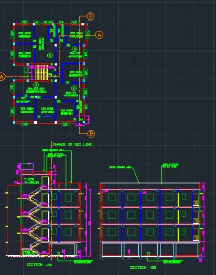
AIM: Create the Plan and Sections as shown in the Figures. Use proper dimension techniques and dimension styles to document the project. Assume the sizes of the doors and windows as per construction standards. Refer to sections for stair details if required.
INTRODUCTION: Draw a section of a given floor plan by refrence of section line AA % section line BB with all details, by using auto cad 2019 and use commands like line, extend, line layer, dimension, text, hatch, offset, array, multileader & layer from layer properties. all dimension in mm (decimal)
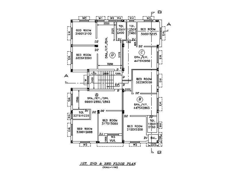
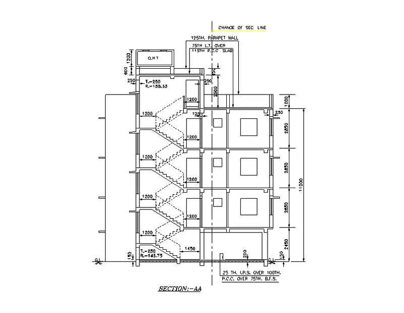
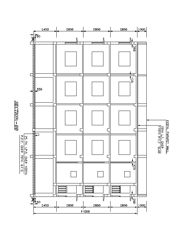
Procedure:( For Floor Plan )
Step 1)
unit & scale setting
open the auto cad as imperical setup
set unit as Decimal and all units in mm
now set scale from directly tool bar or type SCALE in dialog box
set scale as 1:100 means 1 unit on paper is 100 unit on ground or field
Step 2)
making floor plan ( Devlopment )
choose a construction line from draw bar
draw verticle and horizontal line ( construction line )
then take offset command ( OFFSET )
and offset both construction line ( horizontal, verticle ) at a distance of 250mm as a wall thickness,
then go to horizontal axis and take offset command
and offset at a distance of 2888 for first room from last line
then offset at 125 mm as wall thickness
and then offset at 1225mm with 125mm wall thickness 125mm
angain offset at a distance of 3200mm with 125mm wall thickness
and offset at a distance of 3100mm with wall thickness 250mm as external wall thickness
now go to verticle axis and offset at 3100mm from last line with 125mm internal wall thickness
then again offset of 2550mm with 125mm wall thickness
now two times(repeat for twise) offset with 1250mm with 125mm internal wall thickness
and finnally offset with 3000mm with 250mm external wall thickness
now from top horizontal side take offsets upward on 250mm wall thickness
then from previous line take downward offset on 3225mm with 125mm wall thickness
then again offset of 2950mm with 125mm internal wall thickness
then again offset of 3050mm with 125mm internal wall thickness
then again offset of 2863mm with 125mm internal wall thickness
then again offset of 3300mm with 125mm internal wall thickness
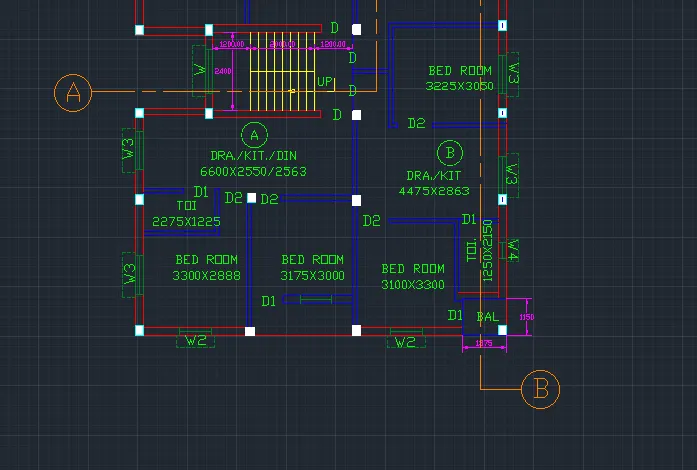
and on bottom last room(master bed) corner make toilet of 1250X2150mm with internal wall 125mm and external wall 250mm
trim extra lines using (TRIM) command
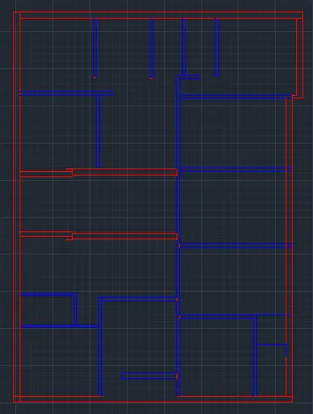
Step 3) doors, columns, windows and staircase
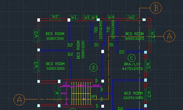
provide doors and window of following dimensions
window,
W = 1400 X 1200mm
W1 = 800 X 900mm
W2 = 1000 X 1200mm
W3 = 1200 X 1200mm
W4 = 500 X 900mm
chajja 100mm projection of each side with 400mm length
&
Door
D = 1100mm
D1 = 1000mm
D2 = 900mm
Column of size 250 X 300mm
by using line command, set line from layer property and set layer with green colour draw windows according to assume size with inner panel line of 25mm thick
now, by using line command, set dash line from layer property and set layer with green colour and draw chajja with 100mm projection and 400 length
by using line command, set line from layer property and set layer with sky colour, draw colums of size 250mm X 300mm as shown in fig
then use hatch command ( HATCH )
and take solid hatch with wite colour and draw over all columns
and Trim extra lines by using TRIM command
staircase;
add layer for stair case from line property and gives yellow colour
take offset command (OFFSET) and take 250mm as a tread
and gives 8 offset of 250mm you get flight now divide it horizontally to make 2 flight
and by using multi leadre command gives direction leader to stair
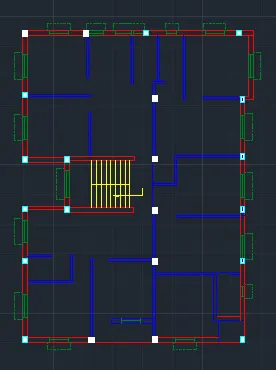
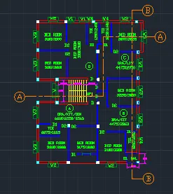
step 4) naming and detailing with dimensions and also section line
Go to the text command or DTEXT set the dimensions(Scale )
and from line property gives it a colout as text line
and gives names ( text as shown in fig )
now select layer for dimension and gives it diffrent colour
then gives dimensior where it required and modify by if required
then draw section line AA and Section line BB, select line from line layer ( short dash long dash line )
and draw it as shoen in fig with diffrent colour layer
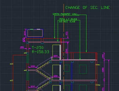
Procedure: for section AA
step1 )
choose construction line from draw command
extend all refrence line from devlope plan which are comes in section a by using verticle line
draw this all line using external line and internal line layer from layer propert (red & blue )
then take offset command OFFSET
and offset all elevation( height as per dwg )
choose line command and draw horizontal line between end verticle line
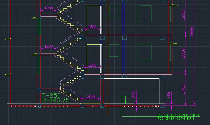
then offst it 200mm for base
then 2450mm for first floor with 115mm slab thickness
now again offset of 2850mm with 115mm slab thickness
now again offset of 2850mm with 115mm slab thickness
now again offset of 2850mm with 115mm slab thickness
now again offset of 1000mm with 115mm slab thickness for parapet wall
now agin offset of 2550 with 125mm wall thickness for head room
then again 450 for parapet wall
now draw a over height water tank by offseting 1200mm from previous line
ang goves 115mm slab thickness over all tank from inner side
now by using TRIM command trim extra lines as shown in fig and make it as frame
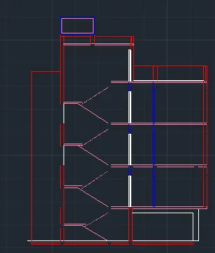
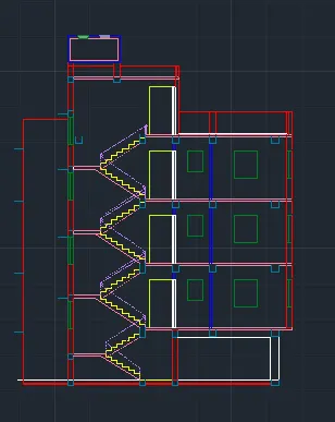
step 2) stair case with grill and landing and window, door and beams
take ortho on
choose stair line layer command from line layer
choose a line, and go for first floor steps
draw a atep from GF line with tread- 250mm and riser- 143.75mm
then make 9 trad and 8 riser according dimension
then draw flight on front of last step with 115mm slab thick
and draw west beam for staircase by providing 250X275mm beam
and same do for next flight
now go for second floor stair
here take Tread- 250 and Riser is-158.33
draw it from first floor slab level and make 9 trad and 8 rised according to dimension
then on last line draw flight of length 1200mm with slab height 115mm
and draw west slab on bottom wich is resting on 250X275mm beam
same do for second flight wich starting from landing to second fllor
then copy the whole staircase section of FF and copy it for second and third floor
now draw stair case grill by using dash dash line layer from home tab
by choosing line command take 500mm height at every starting stair
and connect it by same layer and fillet it at junction with 5mm radius
draw samw grill overall stair section
now draw window of 1200mm height below from lintel with thick as wall thickness
draw below every flight beam with pannels of thick 20mm
create 2 opening for OHT of 1000mm width
then draw beam by using beam layer command from layer property
with depth of beam is 275mm and width is 250mm
draw all over where we cut the section and beam are visible
now same draw room windows by refrencing section lines from plans
draw it by 1200 mm depth for room window and 900mm depth for WC windows
then door
take door line layer from layer property and draw doors of 2100mm height from following refrence lines
and also draw all window projection for last wall, below the lintel with 20mm middle pannel
step3) chajja, text, dimension, GL, and leader & section line
take chajja layer property and gives it colour from layer property
and draw all chajjas of 400mm length with 1:75 slope
then by using array path command (ARRY)
first draw 1 line and acoording to that array line with path for bottom of GL as filling material
then use multileader go to setting make on proportinal schale and modify it
then draw multileder with right justify and text above the underline
and gives all specification as shown in fig using multileader
now select line layer for dimenssion
type DIM on dialog box modify setting make it text is along the line and change scale ( also from annotation )
then take linear dimension and take first base dimension then by using continue dimension and base dimension draw all the dimension
after that final stage is text
type DTEXT on dialog box go eith text setting fit scale with over all proper dimension
then using multi line text write all text required for dwg
and gives layer colour as purpol
draw section line using long dash short dash layer line from home tab
and gives it orange colour with proper proportinal scale
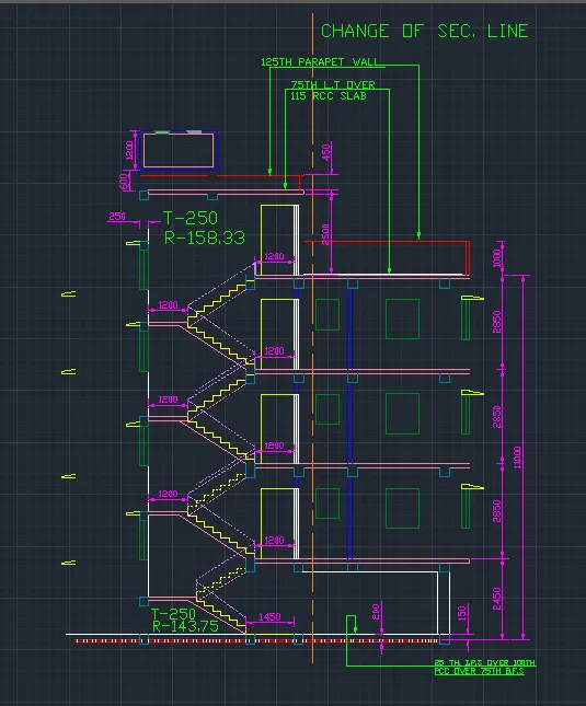
step 4) final section AA dwg
mearged all the stage make a final section AA dwg
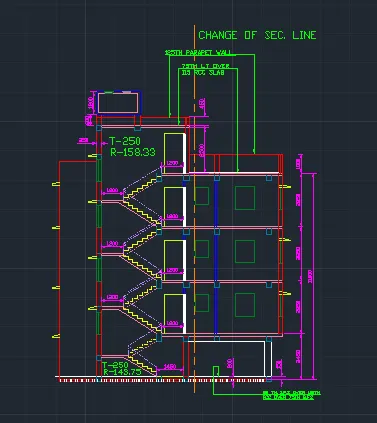
Procedure for section BB:
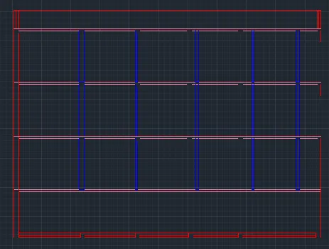
step1 )
choose construction line from draw command
extend all refrence line from devlope plan which are comes in section a by using verticle line
draw this all line using external line and internal line layer from layer propert (red & blue )
then take offset command OFFSET
and offset all elevation( height as per dwg )
choose line command and draw horizontal line between end verticle line
then offst it 200mm for base
then 2450mm for first floor with 115mm slab thickness
now again offset of 2850mm with 115mm slab thickness
now again offset of 2850mm with 115mm slab thickness
now again offset of 2850mm with 115mm slab thickness
now again offset of 1000mm with 115mm slab thickness for parapet wall
now agin offset of 2550 with 125mm wall thickness for head room
then again 450 for parapet wall
now draw a over height water tank by offseting 1200mm from previous line
ang goves 115mm slab thickness over all tank from inner side
now by using TRIM command trim extra lines as shown in fig and make it as frame
step 2) windows, door and beams & balcony
take ortho on
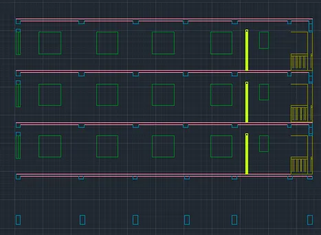
draw window of 1200mm height below from lintel with thick as wall thickness
draw below every flight beam with pannels of thick 20mm
create 2 opening for OHT of 1000mm width
then draw beam by using beam layer command from layer property
with depth of beam is 275mm and width is 250mm
draw all over where we cut the section and beam are visible
now same draw room windows by refrencing section lines from plans
draw it by 1200 mm depth for room window and 900mm depth for WC windows
then door
take door line layer from layer property and draw doors of 2100mm height from following refrence lines
and also draw all window projection for last wall, below the lintel with 20mm middle pannel
draw a balcony as a refrence of plan construction line
by setting diffrent layer for it from layer property with inner gril
step3) chajja, text, dimension, GL, multi leader for text & shutter frame, parapet wall
take chajja layer property and gives it colour from layer property
and draw all chajjas of 400mm length with 1:75 slope
then by using array path command (ARRY)
first draw 1 line and acoording to that array line with path for bottom of GL as filling material
then use multileader go to setting make on proportinal schale and modify it
then draw multileder with right justify and text above the underline
and gives all specification as shown in fig using multileader
now select line layer for dimenssion
type DIM on dialog box modify setting make it text is along the line and change scale ( also from annotation )
then take linear dimension and take first base dimension then by using continue dimension and base dimension draw all the dimension
after that final stage is text
type DTEXT on dialog box go eith text setting fit scale with over all proper dimension
then using multi line text write all text required for dwg
and gives layer colour as purpol
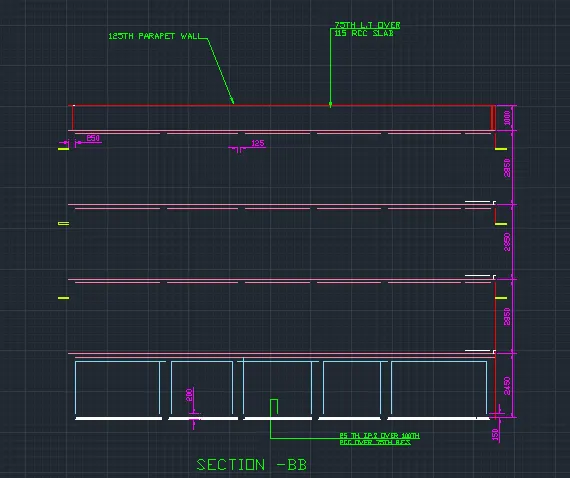
step 4) final dwg of BB section
mearged all dwg and make final one ( by on all layer )
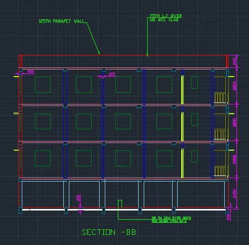
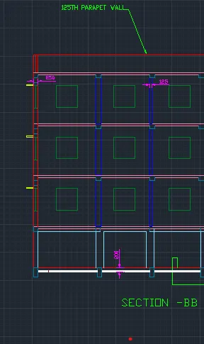
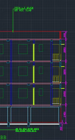
Result : We Draw the Plan and Sections as shown in the Figures by using edit and modify commands in auto cad with dividing various steps, we got the clear visuial and readable for easy understanding dwg during execution on site or varios purposes
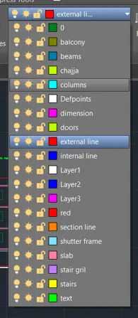
following are various layer use for dwg
NOTE: final PDF attatch to challenge