Reinforcement detailing of Columns from ETABS output
Reinforcement detailing of Columns from ETABS output
Reinforcement detailing of columns in Etabs 2018.
The ETABS file for a G+4 building is provided. Run the analysis and design the RCC Moment Resisting Frame. The following challenge deals specifically with two columns at the following grid intersections.
- 3A
- 3B
- Provide details of longitudinal reinforcement for the two columns, from foundation to terrace level. Sketch the column cross sectional & elevation details or draft it using autocad software.
- Show shear reinforcement & lapping details as per special confining reinforcement provision of clause 8.1 of IS 13920 - 2016
Aim: to know how the quantity of steel required in given column section, or details of given two RC beam
Introduction: work on the check satisfaction, its satify the IS with analys values, to ensure the load capacity of member over the load demand
Procedure:
step 1)
open the plan provided in challenge
in etabs 2018
open first floor plan
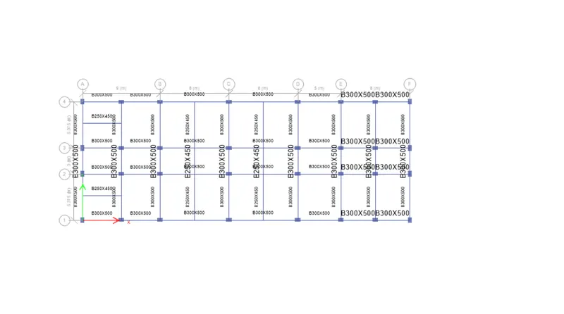
step 2)
Analys the structure
by clicking on run anlyasis tab
we get the maximum and minimum deflection
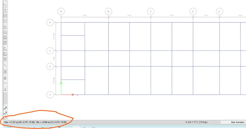
step 3) concrete frame design
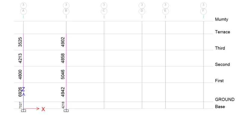
click on concrete frame design button to know the longitudinal and axial reinforcement of all the frames
like column and beams
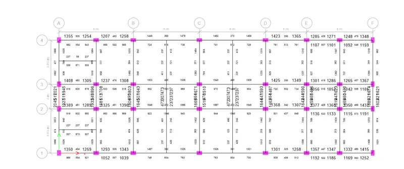
step 4) check shear reinforcement as well
go to concrete frame option
droup down the button and click on the
display design frame
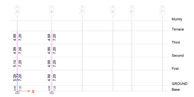
step 5) reinforcement detaling on auto cad
Longitudnal reinforcement for the two columns from foundation to terrace:
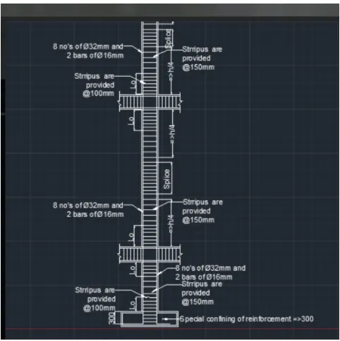
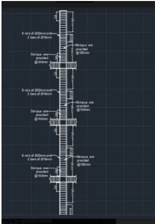
Grid A
From base to terrace the maximum Ast=6926 sq.mm
So we can provide 8 bars of 32mm=8x803.84=6430.72sq.mm
3 bars of 16mm=3x200.96
=602.88sq.mm
Total Ast=7033.6sq.mm
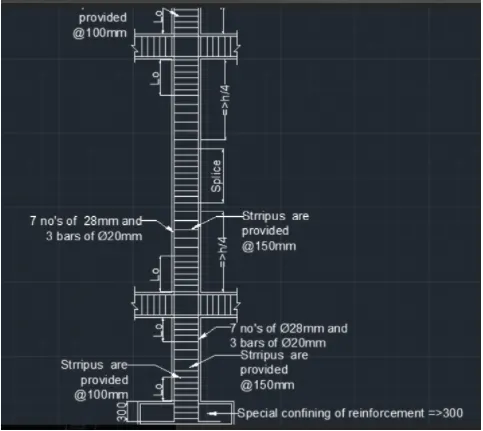
Grid B
From base to terrace the maximum Ast=4942 sq.mm
So we can provide 7 bars of 28mm= 7x615.44
3 bars of 20mm=3x314
Total Ast=5250.8sq.mm
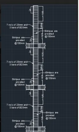
step 6) special confining reinforcement
As per clause 8.1 of IS13920-2016, the special confining reinforcement is calculated and verified with the drawing detail.
As per cluase 8.1 section a), the confining reinforcement length lo">loloshould be at least
i) larger dimension of frame member (650mm)
ii) 1/6th of clear span (575mm)
iii) 450mm
So lo">lolo= 650mm
As per cluase 8.1 section b), the maximum spacing of confining reinforcement shall be
i) 1/4th of minimum member dimension (112.5mm)
ii) 6 times of smallest longitudinal rebar (120mm)
iii) 100mm
So maximum shear link spacing maintained = 100mm
Minimum special confining reinforcement should be maximum of (a) and (b)
(a) Ash">AshAsh= 0.18 svh(fckfy)((AgAk)-1)">svh(fckfy)((AgAk)−1)svh(fckfy)((AgAk)-1)
(b) Ash">AshAsh= 0.05 svhfckfy">svhfckfysvhfckfy
(a) Ash">AshAsh= 631 sq.mm/m
(b) Ash">AshAsh= 337 sq.mm/m
Required minimum special confining reinforcement at joint Ash">AshAsh= 631 sq.mm
Provided shear reinforcement at joint = (1000100)">(1000100)(1000100)x 4 legs x area of 8mm dia rebar (50.3 sq.mm) = 2010 sq.mm
Hence OK.
Result: detailing of given column RC member is done with check on special confining reinforcemnt is done for shear reinforcement,
Detailing of grid A3 column
Detailing of grid B3 column