Assignment 6-Frontal Crash Simulation Challenge
AIM:
To perform a frontal crash test with the given BiW frame in Radioss and request for outputs.
OBJECTIVE:
The objective of this project is to learn to perform crash analysis and the parameters surrounding it.
MODEL SETUP:
The model setup is a reduced version of a full car FE model for the frontal crash.
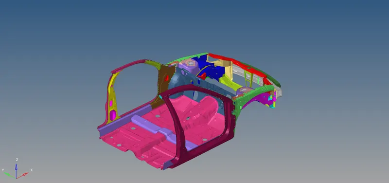
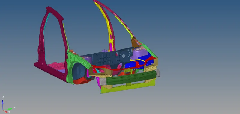
There is a front bumper component which is meshed with solid elements along with a rail attached with it. There is a shotgun shaped component attached in the side portion of the BiW. There is also a suspension shock tower where the front suspension is mounted. Attached to the suspension shock tower is the side fender assembly. Following that, we have the A and B pillars along with connected roof lines and a floor panel. The floor panel has two cross members and two longitudinal members.
PROCEDURE:
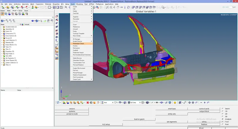
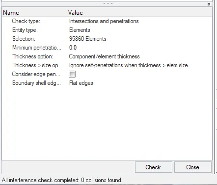
The project is started with checking the unit system consistency. Following that, the intersection & penetration check is done and penetrations & intersections are cleared.
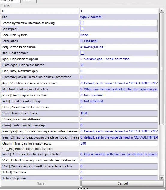
Appropriate contact interfaces are given between the components with recommended parameters.. A self contact (type 7 ) is also given for the BiW.
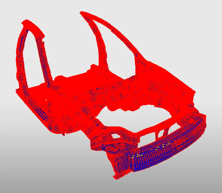
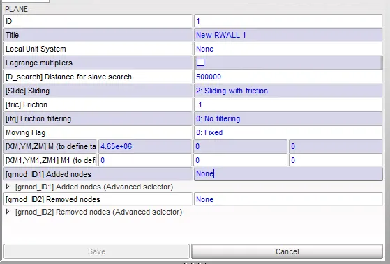
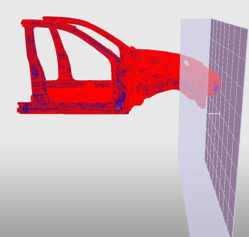
Rigid bodies are also checked and any issues in them are resolved. An infinite planar rigid wall is created with friction 0.2.
The model weight is maintained at 700 kg by adding mass at appropriate places.
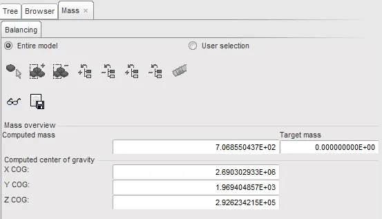
After the masses are added, the CG point is checked.
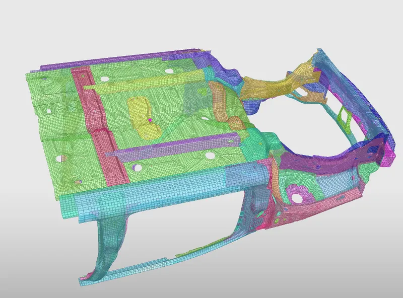
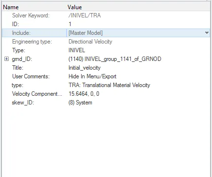
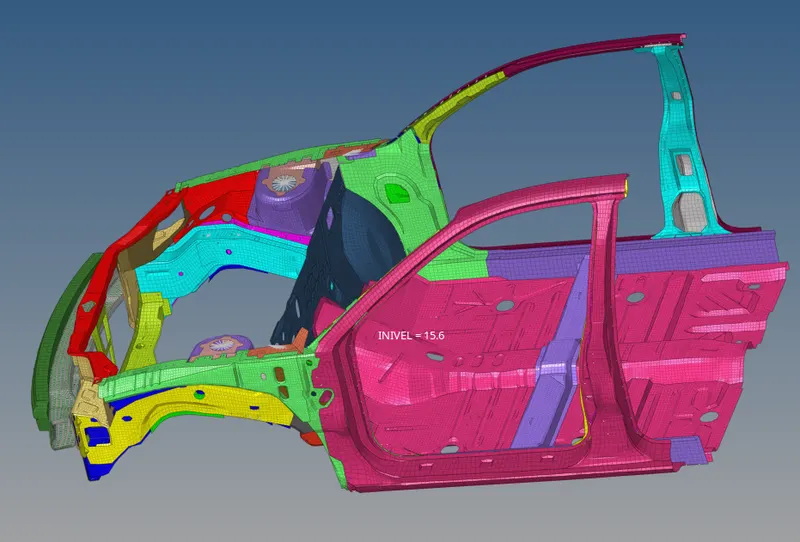
Initial velocity of 35 mph (15.6464 mm/ms) is applied to the frontal BiW.
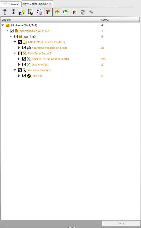
Once the above processes are completed, the model is imported into HyperCrash and the model checker is run. The errors if any are resolved.
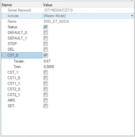
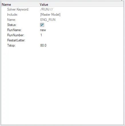
The time step is kept at 0.0005 ms and the model is solved for 80 ms.
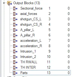
Output requests are given as follows:
- Sectional force in the rails at location of indicated node 174247.
- Axial force received on the rails from the bumper.
- Shotgun cross sectional forces.
- A pillar cross section.
- Acceleration curve received on the accelerometer at base of B pillar (on B pillar rocker).
- Intrusions on the dash wall 66695,66244.
RESULTS & OBSERVATIONS:
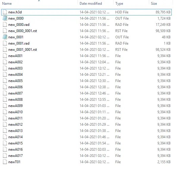
Once the solving is completed, we have the output files - 0000.out, 0001.out, h3d file and the T01 file.
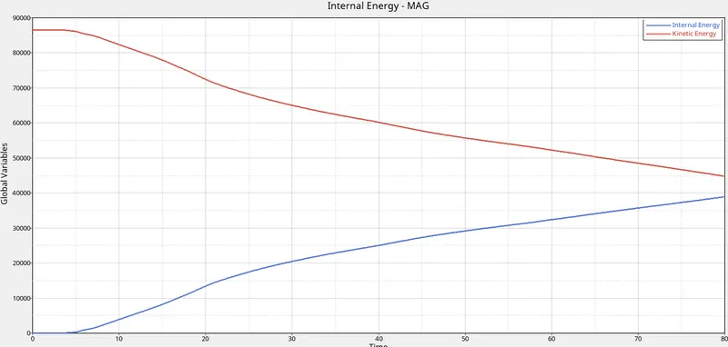
The output plots are plotted in HyperGraph. Comparing the internal & kinetic energy curves, we can say that the kinetic energy of the system is converted into internal energy as the analysis is carried out.
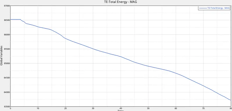
The total energy, as always, is seen decreasing from the moment the BiW collides with the rigid wall.
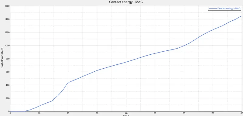
The contact energy increases from 5 ms till the end of the analysis.
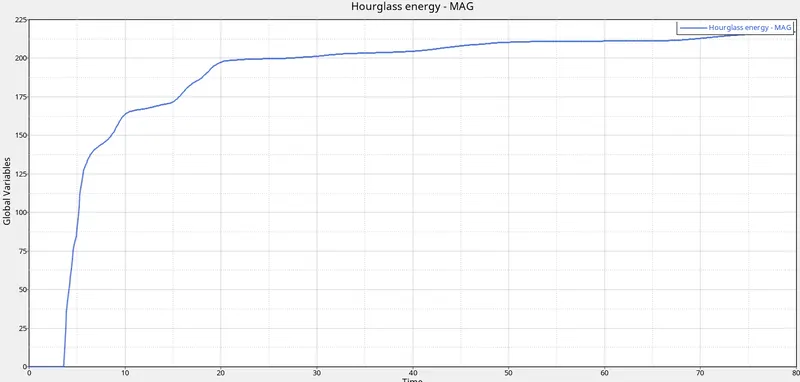
There is a small amount of hourglass energy which is negligible.
Sectional force in the rails at location of indicated node 174247
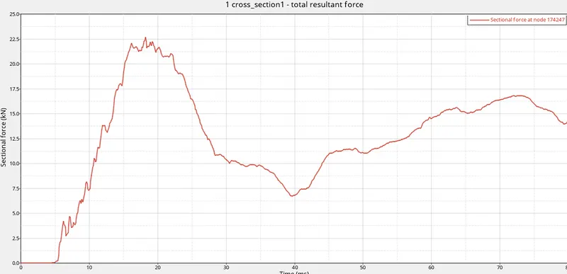
From the plot, we can see no force till 5 ms. As the BiW collides with the rigid wall, there is a force experienced. The peak force reaches 22.8 kN and then the force drops. We can see an increase in the curve as the force is being applied on the rail. Then there is a decrease as the component is absorbing the force received.
Axial force received on the rails from the bumper
The axial force is measured at the rails behind the bumper. This is to know how much force is experienced by the vehicle in an actual crash scenario. We know that the force experienced by the vehicle during the crash is distributed to the roof line, A pillar and to the bottom floor panels. The force received from the rails is the force distributed to these components.
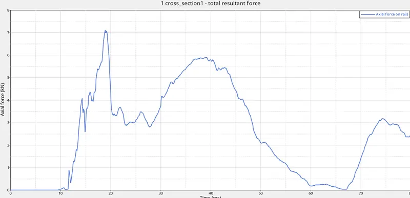
This force starts appearing as the BiW starts colliding with the rigid wall. The maximum force reaches 7 kN. After that there is a steep decrease and then the curve again rises. Thereafter there is a less steeper decrease. This increase & decrease in the axial force is due to the absorbing of the force from the crash by the rails. When they deform, the force is decreased.
Shotgun cross sectional forces
The shotgun cross sectional forces are the sectional force experienced at the shotgun component in the frontal BiW. This component is present in the left & right sides.
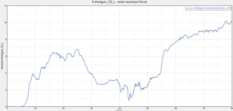
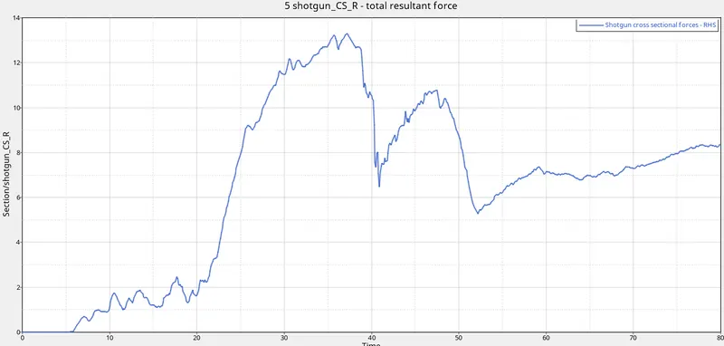
On comparing the cross sectional forces on the left & right sides, we can see that on the right side, the forces are higher than on the left side. After reaching 55 - 56 ms, the force on the right side decreases and on the left side increases.
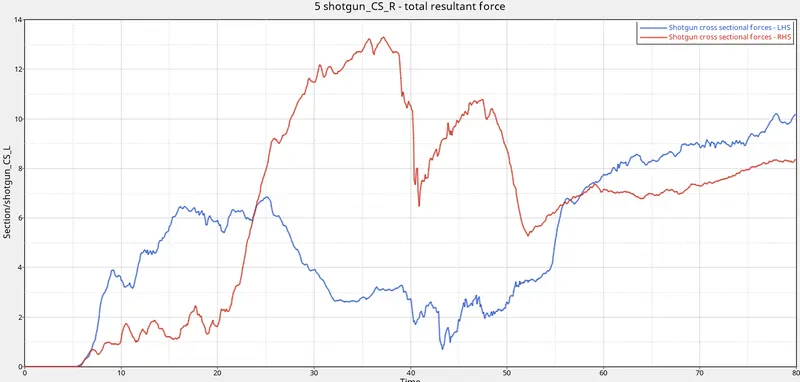
The cross-sectional force is the highest in the right hand side, during 20 to 40 ms in the analysis. It makes a peak value of 13.5 kN.
A pillar cross section
This force is calculated at the A pillars of the BiW on the left & right sides.

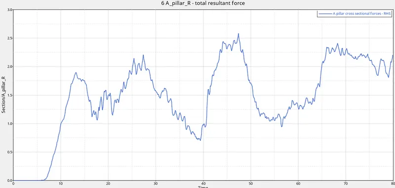
Comparing the forces on both sides, we can see the cross-sectional force more on the left hand side than the right hand side in the beginning upto 40 ms. Eventually, the cross sectional force on the left side decreases and on the right side, it increases.
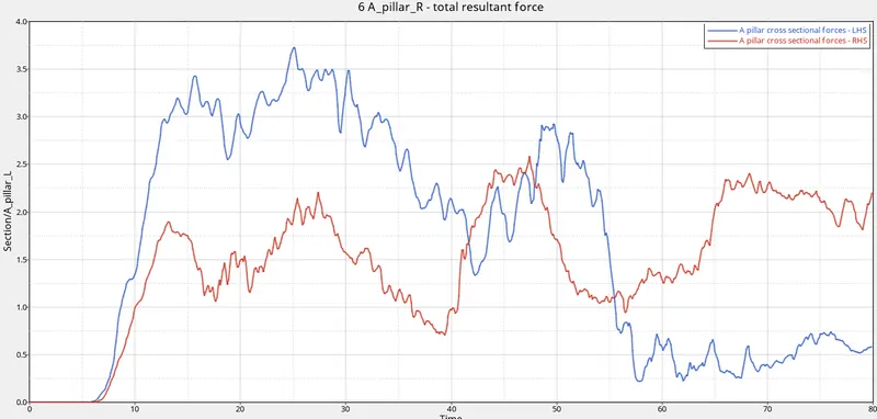
From this we can say that the force from the crash impact has first reached the left side A pillar and only after a time span has reached the right side A pillar.
Acceleration curve received on the accelerometer at base of B pillar (on B pillar rocker)
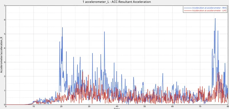
Looking at the acceleration curves obtained at the accelerometer, we can see max. acceleration of 6.1 mm/ms2 on the right hand side accelerometer. This acceleration figure is obtained at the completion of the analysis, i.e. when the crash has almost completed.
Intrusions on the dash wall - node 66695 & 66244
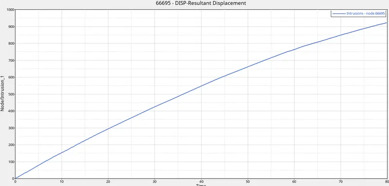
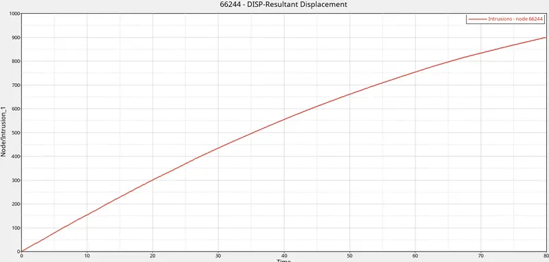
On importing the .h3d file into HyperView, we can see the crash animation. By applying contours, the maximum von mises stress obtained is 3.707E-01 which is 0.3717. The maximum displacement obtained is 1.133E+03 mm which is 1133 mm.
CONCLUSION:
From the above project, the frontal crash analysis is performed on the BiW frame. The appropriate contact interfaces are defined along with a self-contact with type 7 contact. Rigid wall was created with required parameters and initial velocity is set to 35 mph. The model weight is kept at 700 kg. The model is checked for penetrations & intersections and the analysis is performed for 80 ms.
After the analysis was performed required outputs were obtained from the analysis.