Week 8-3D Tetra Meshing Challenge
AIM:
To create tetra mesh for the given set of components.
OBJECTIVE:
The objective of the project is to get familiar with solid meshing and the methods of clearing quality issues for tetra elements.
MODEL:
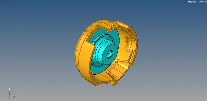
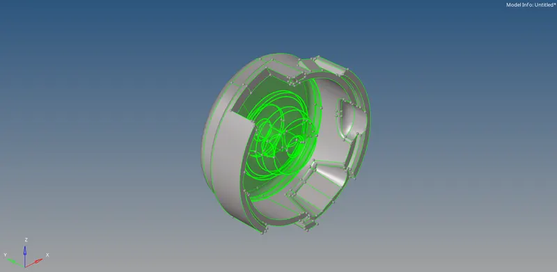
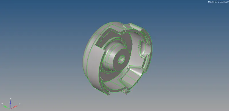
1. Housing:
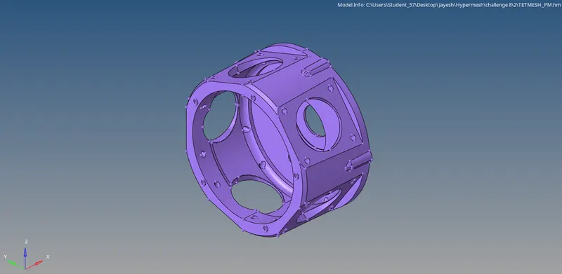
2. Crank casing:
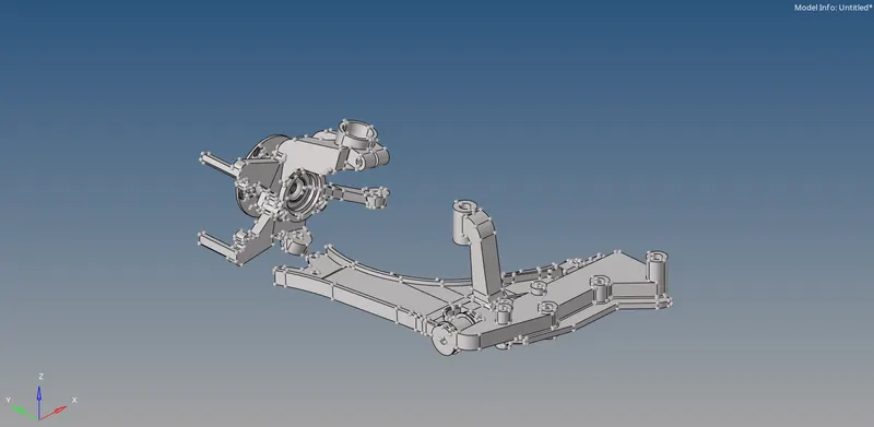
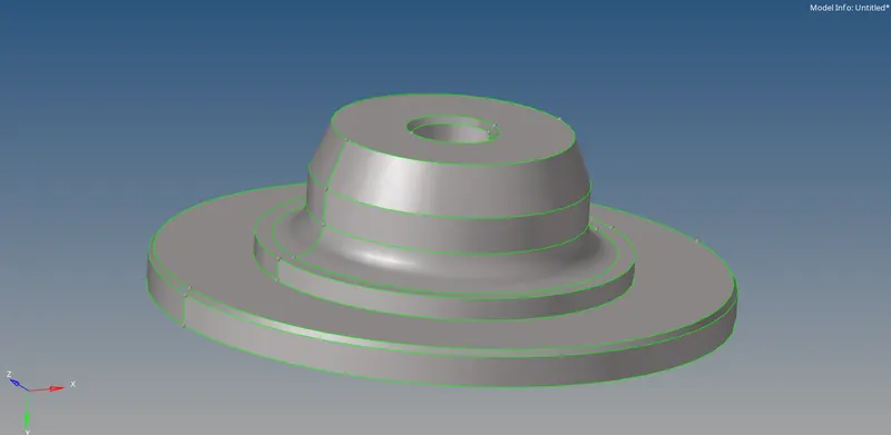
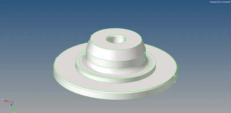
3. Component 3:
PROCEDURE:
1. Housing:
First the model is imported using the Import model option.
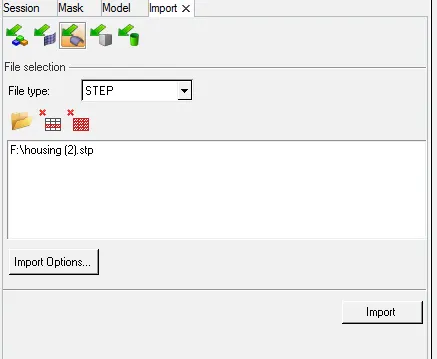
Then the visualisation mode is kept in Topo.
Then, the solids, if any, are deleted using the Delete command.
For this model, we will be using the automatic methods of tetra meshing using Volumetetra in the 3D panel. The meshing will be done for the components one by one.
The meshing parameters such as target element size, 2D element type & 3d element type are set and the meshing is done.

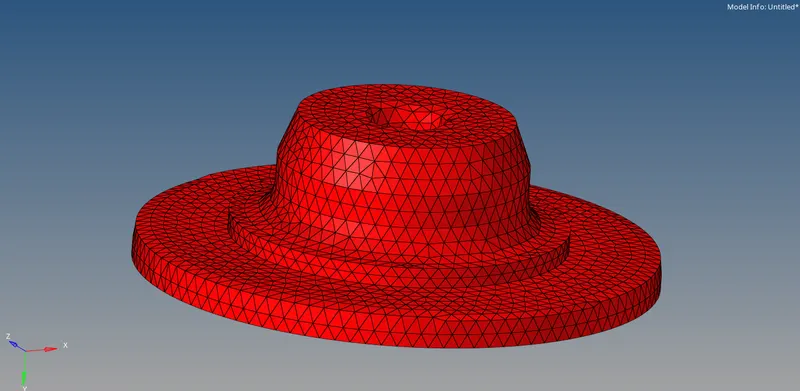
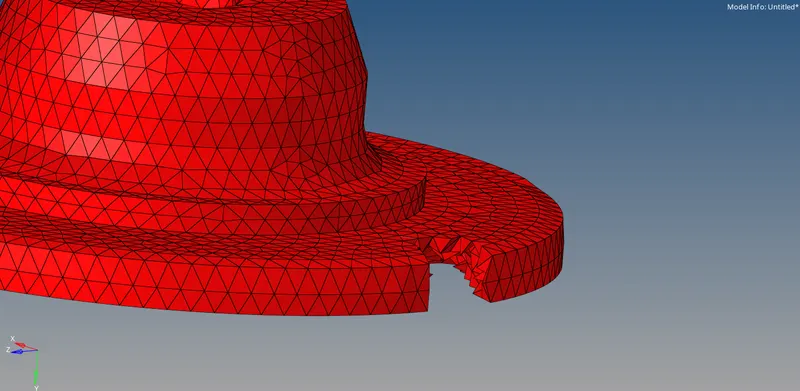
Once the meshing is completed, we can check if the meshing is done properly by masking some elements.
Similarly, the meshing is done for the other component.
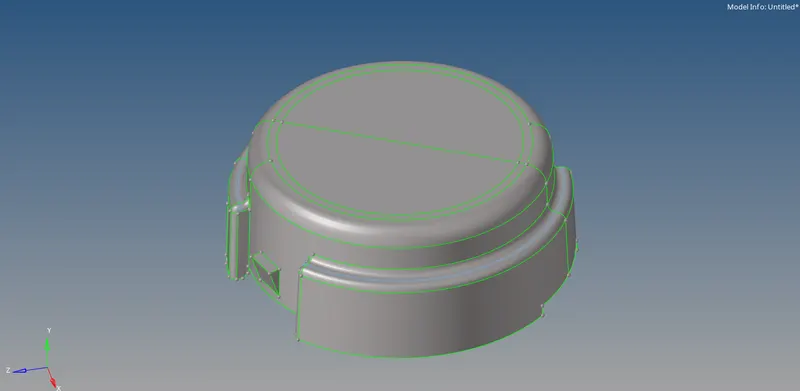
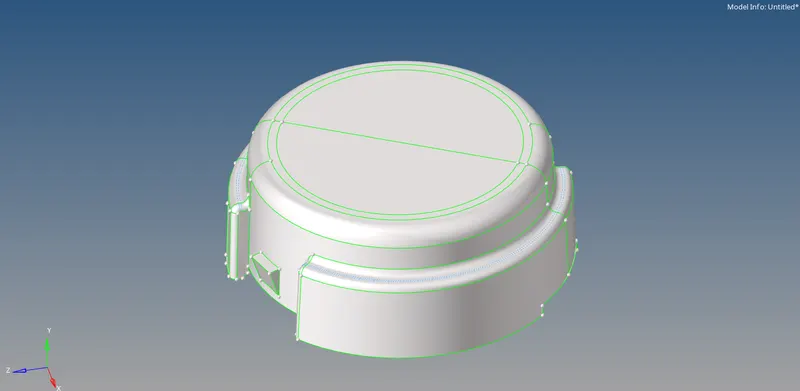
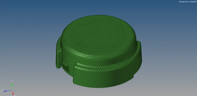
Similarly, we can mask some elements to check if the meshing is done properly.
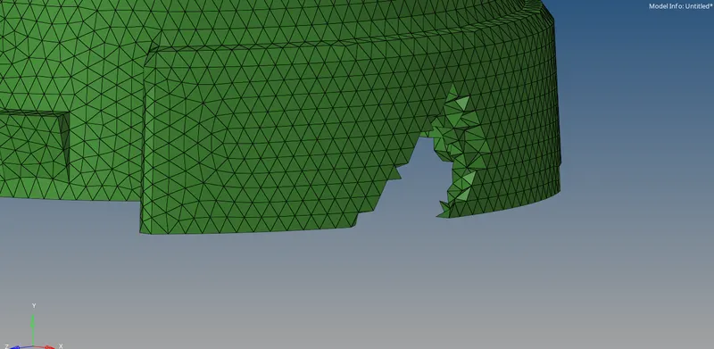
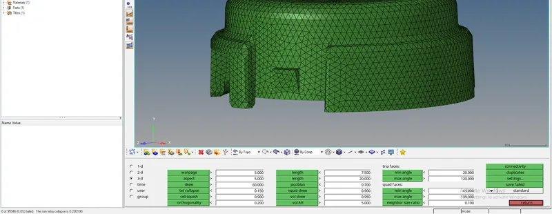
After the meshing id done, we need to check for the Tet collapse of the tetra elements. It is done with the check elements command button.

The tet collapse issues, if any, can be solved by remeshing the components and all the tet collapse issues are solved.
2. Crank casing:
First the model is imported using the Import model option.
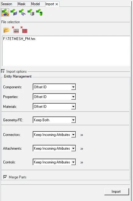
Then the visualisation mode is kept in Topo.
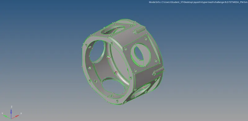
Then the geometry cleanup is done by keeping the geometry in wireframe mode. It helps to see the construction lines and curves better.
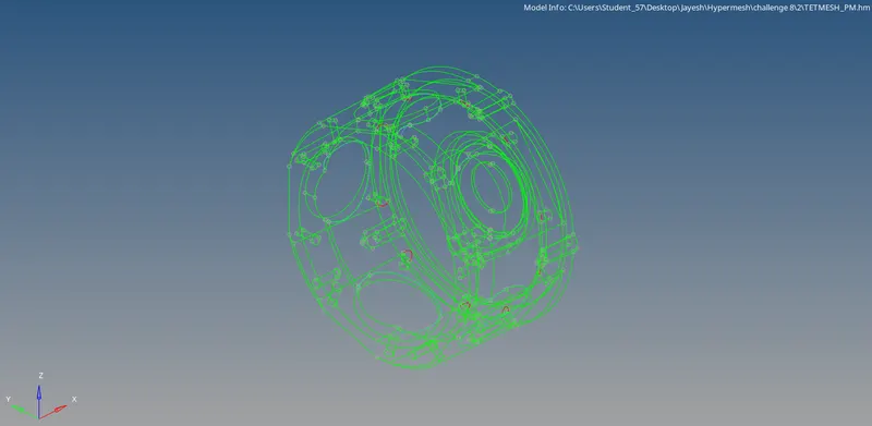
The geometry cleanup is done with the toggle edge command in the quick edit command button (F11).

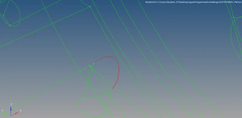
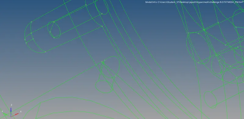
This way, the free edges are toggled and are converted to green edges.
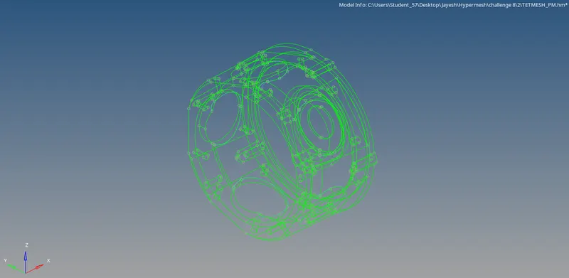
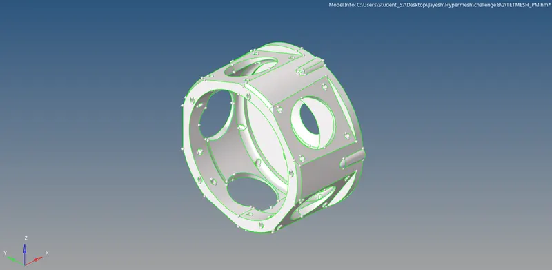
Next the defeaturing of the component is done. This can be done using the defeature command or can be done manually. Defeaturing is done on fillets measuring below the minimum element size.
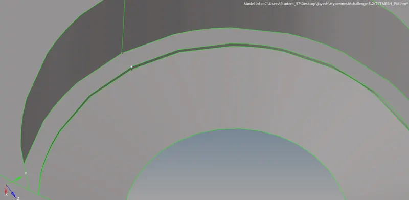

The fillets are removed by replace point command.

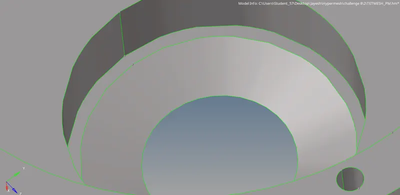
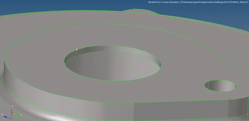
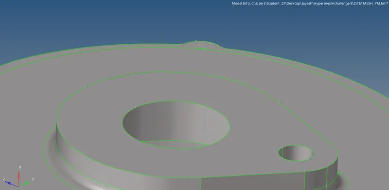
The defeaturing is done by toggling unwanted construction lines using the toggle edge command button.
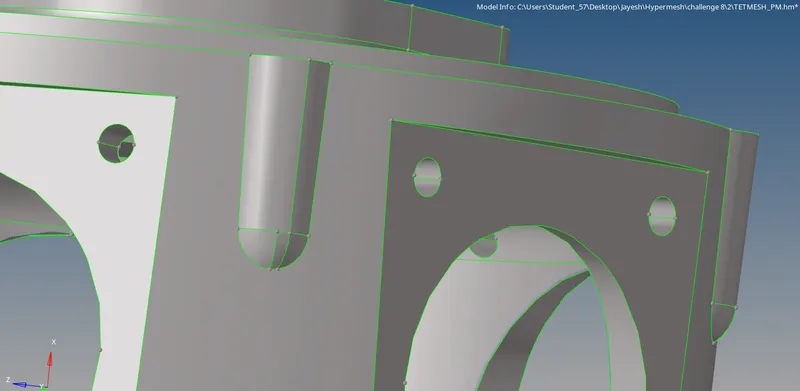
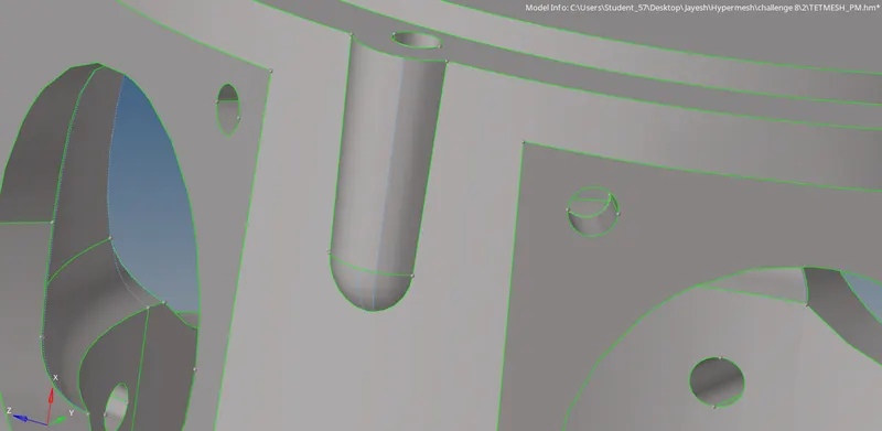
Sharp edges are modified so that elements do not fail at the sharp edges.
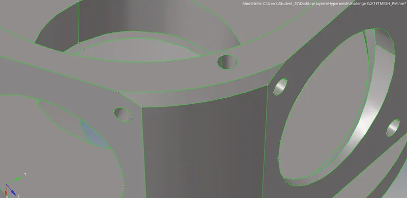

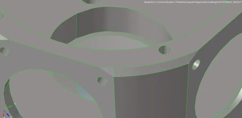
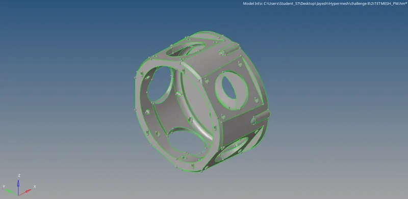
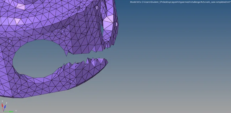
After the defeaturing is completed, the tetra meshing is done.
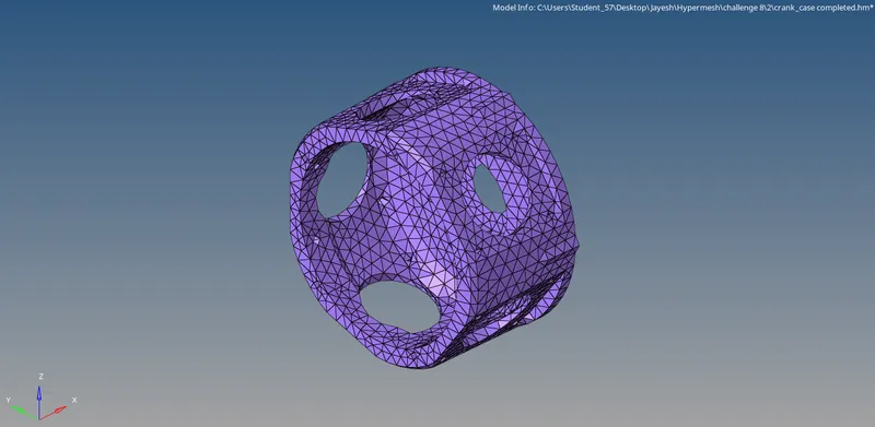
Always, we can check the tetra meshing by masking some elements.
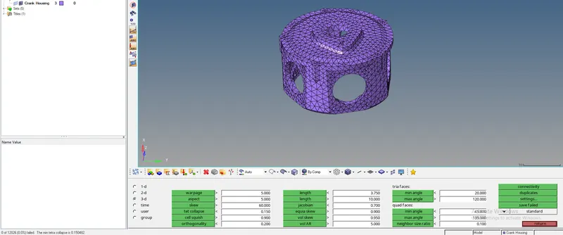
After that, the elements are checked for tet collapse with the help of check elements command.

3. Component 3:
First the model is imported using the Import model option.
Then the visualisation mode is kept in Topo.
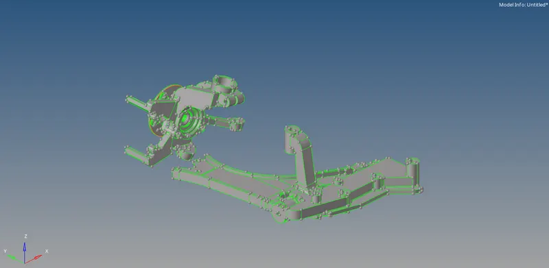
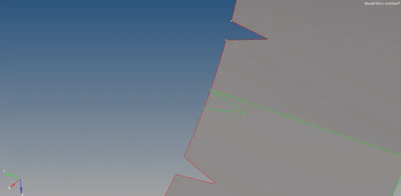
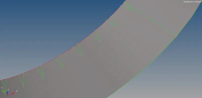
Next the defeaturing and geometry cleanup of the component is done. This can be done using the defeature command or can be done manually.
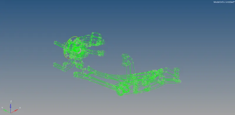
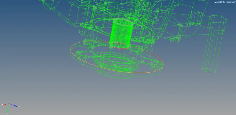
The geometry cleanup is done with the toggle edge command in the quick edit command button (F11).

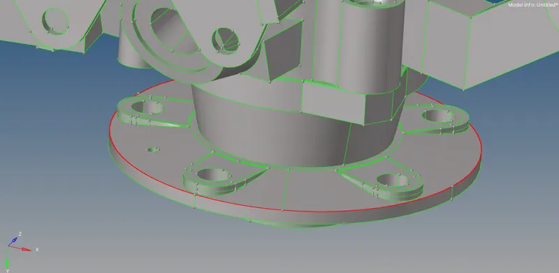
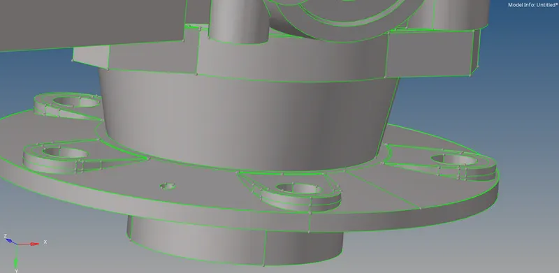
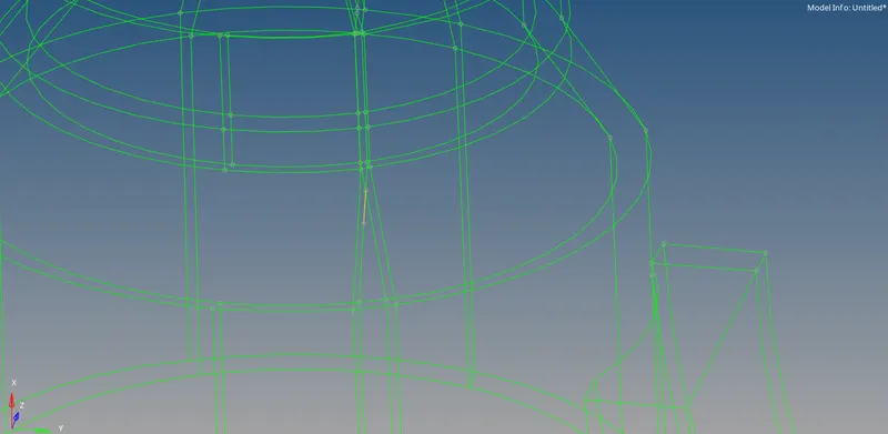
This way, the free edges and T edges are toggled and are converted to green edges. The defeaturing is done by toggling unwanted construction lines using the toggle edge command button. Defeaturing is done on features measuring below the minimum element size. Here we have the gear teeth which will surely fail for minimum element size.
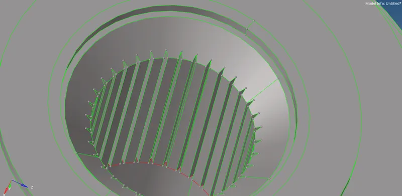
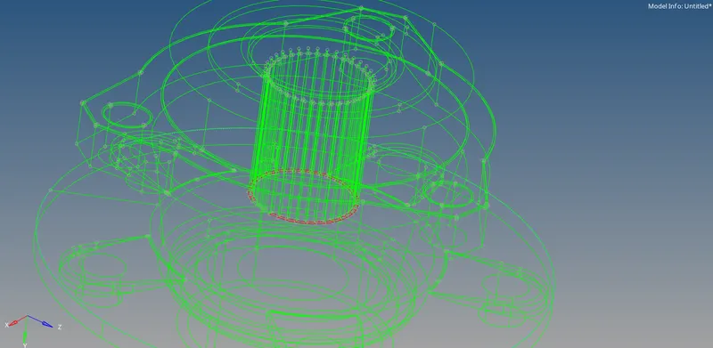
We can delete them and have a plain surface in that place.

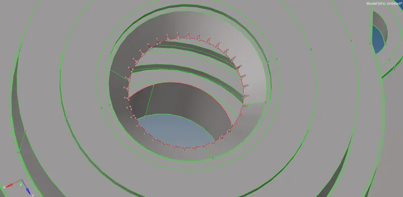
The lines are toggled and then the surfaces are extended.
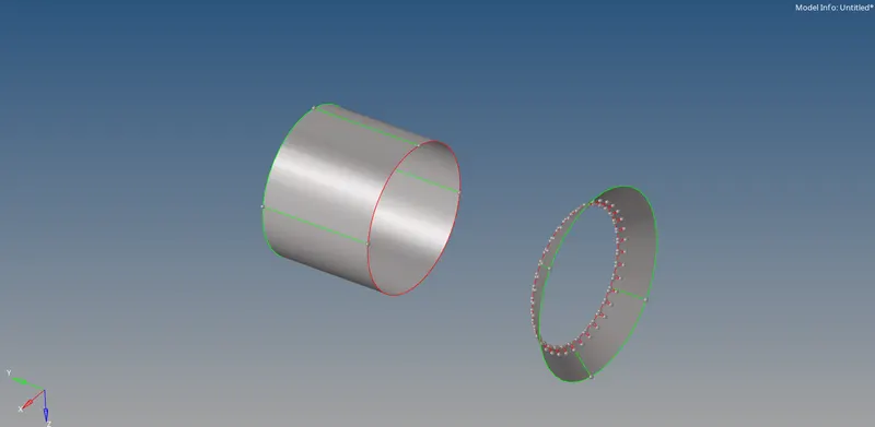
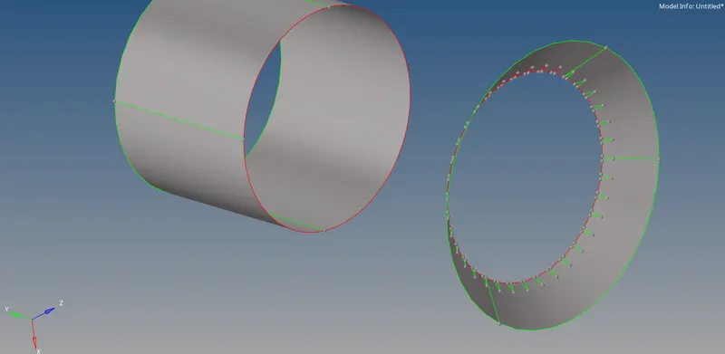
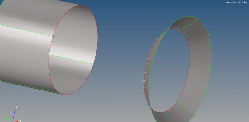

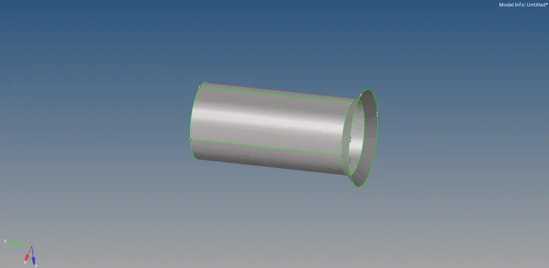
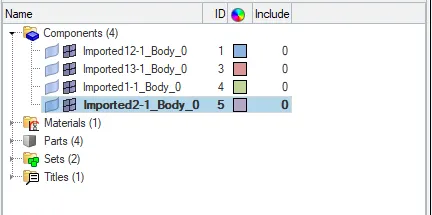
Here we have 4 components in the model.
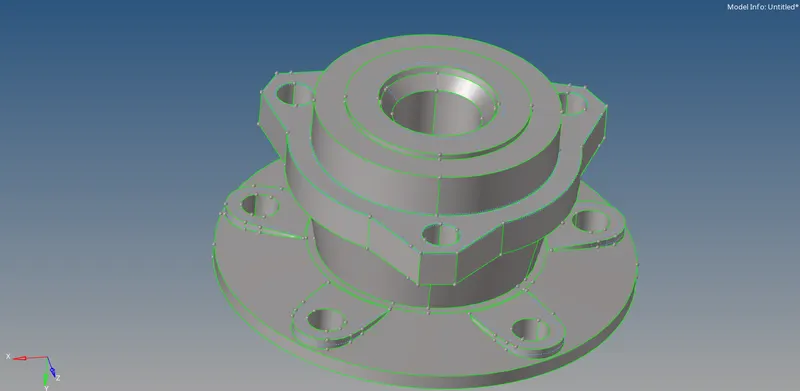
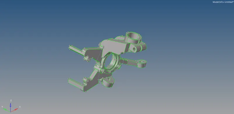
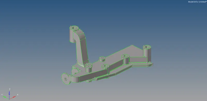
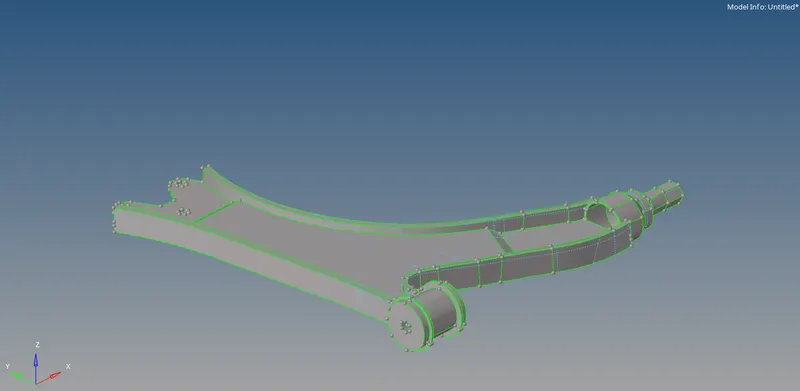
We can use the three methods of tetra meshing to mesh the four components. First method is surface meshing with 2D elements and then converting it to 3D elements. Surface meshing is done in the 2D panel.

The element size is kept as the target element size. The type of elements is kept as trias as these tria elements are later converted into tetra elements.
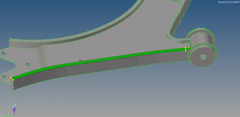
The surface meshing is done with no element failures.
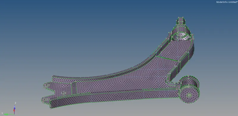
After the surface meshing is completely done, the shell elements are converted to solid elements in the 3D panel.

As a best practise, the maximum & minimum element size for the tetras and tet collapse target value is given in the Tetramesh parameters.

Then the shell mesh is converted to solid in the tetra mesh panel. The components or elements are selected and then meshed.
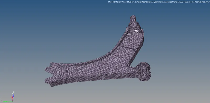
We can mask some elements and check the mesh.
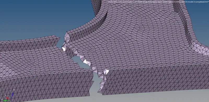
Once the meshing is done, the elements are checked for tet collapse using the check elements command button (F10).
The failed elements can be cleared manually by adjusting their nodes. This is done using the distance command (F4). Another method is by re-meshing the tetra elements using the tetra remesh command in the tetra mesh panel. It is done by selecting the tetra elements and remeshing them.

The next method is the Volume tetra method.

Here, the component is selected and meshed.
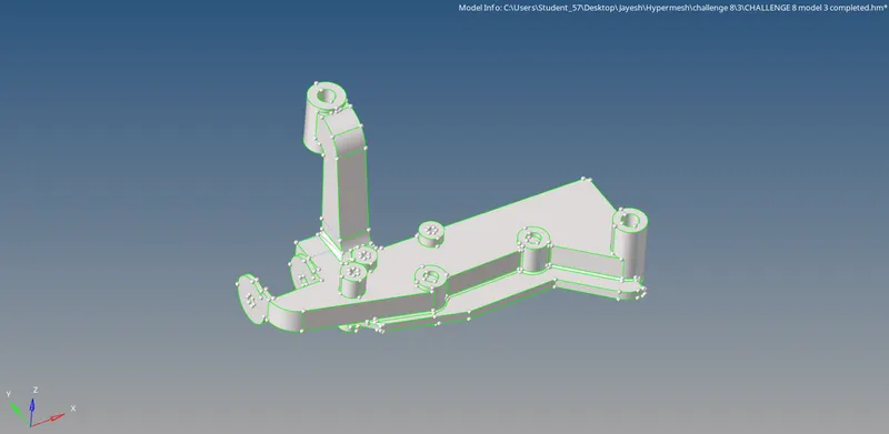
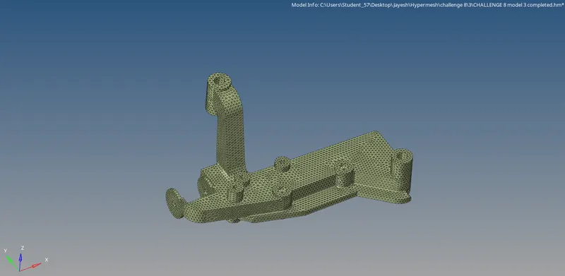
The mesh is checked by masking some elements.
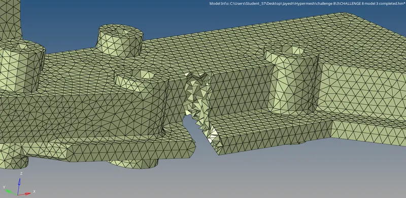
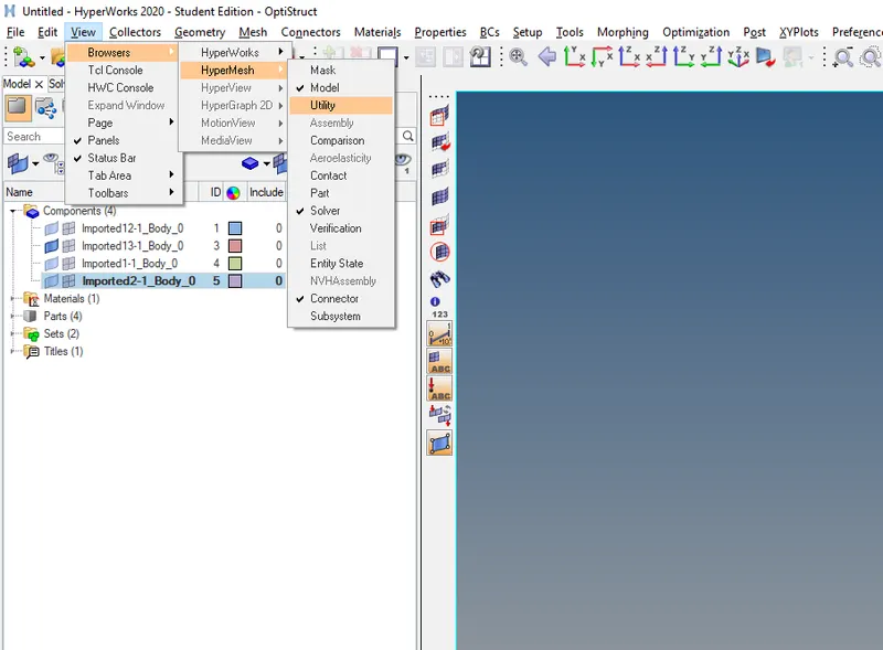
The third method is the Quick tetra method. It is done from the Utility command in the View tab.
In the side window below, the Geom/Mesh button is selected.
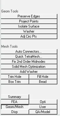
Then under Mesh tools, the Quick TetraMesh command button is selected.
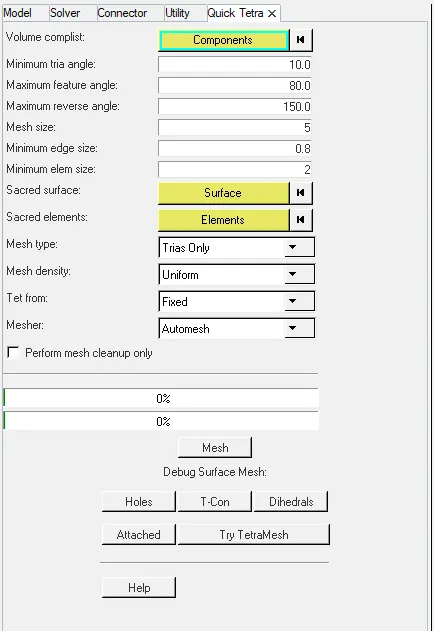
The parameters for meshing are set here and the component is selected for meshing.
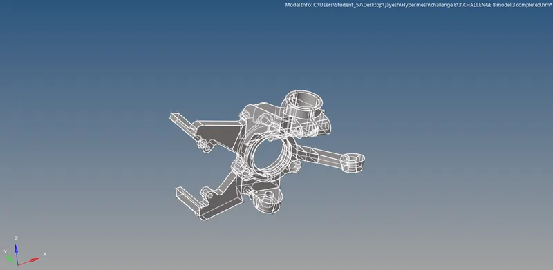
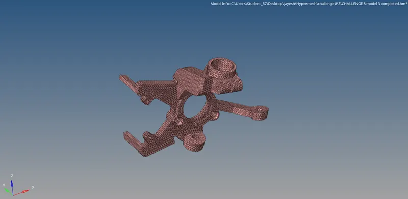
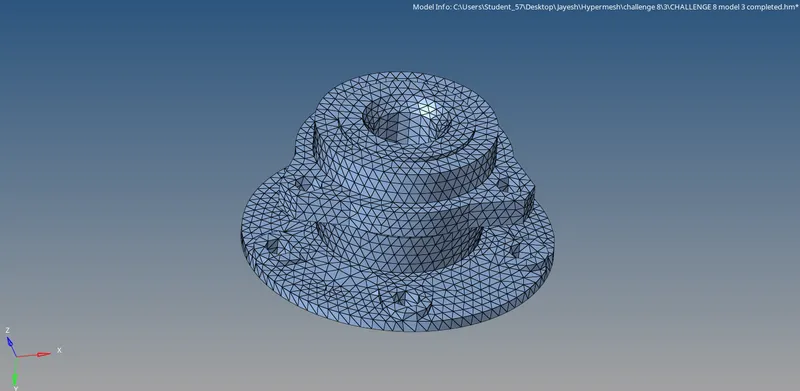
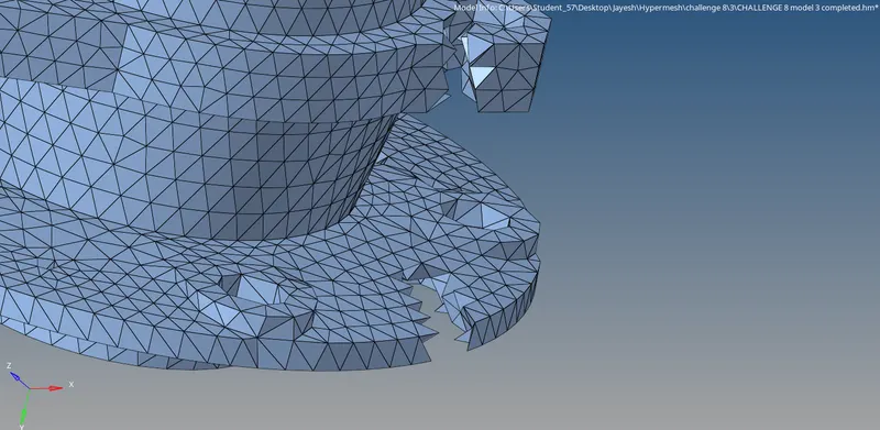
All the elements are cleared for tet collapse and the component is meshed without any quality issues.
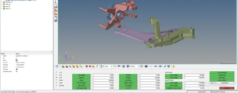
RESULTS:
1. Housing:
Inner part:
Outer part:
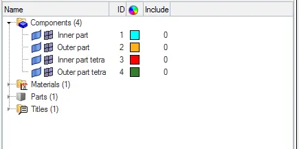
Component collectors:
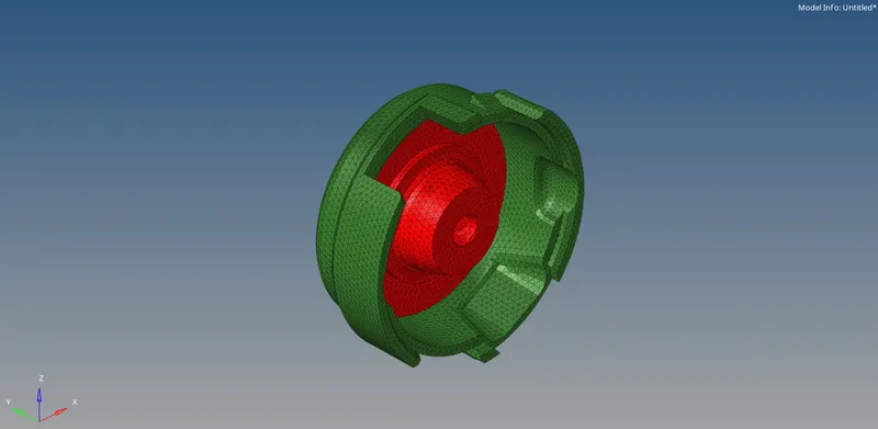
Completed model:
2. Crack case:
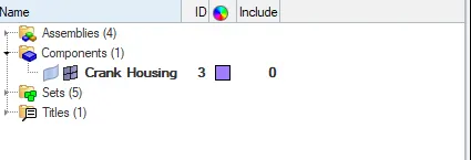
Component collectors:
Completed model:
3. Component 3:
Part 1:
Part 2:
Part 3:
Part 4:
Component collectors:
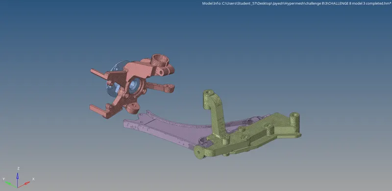
Completed model:
CONCLUSION:
Thus the given components are solid meshed with tetra elements with no tet collapse failures.